E67-5JS0079LINKNET UNISERV UNIT BOOSTER
Powerwave Technologies Inc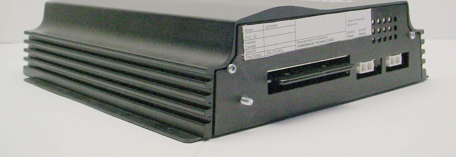
Click to zoom
Application Details
- Equipment Class
- TNB - Licensed Non-Broadcast Station Transmitter
- Date of Grant
- Nov 16, 2005
- Application Purpose
- Original Equipment
- Date of Application
- Nov 16, 2005
- Equipment Note
- LINKNET UNISERV UNIT BOOSTER
- Frequency Range
- 764.00000000 - 776.00000000
- Company
- Powerwave Technologies Inc
- Country
- United States
Documents & Files
Document Text
Text extracted from the exhibit documents filed with the FCC. Open a document above to read the original.
Users Manual
DCM000000104 Rev Q September 2005 Installation, Opera Installation, OperaInstallation, Opera Installation, Operation, tion, tion, tion, Maintenance and User Manual Maintenance and User ManualMaintenance and User Manual Maintenance and User Manual LinkNet UniServ Unit (USU) RF – FIBER Interface Modules © 2005 Powerwave Technologies Incorporated. All rights reserved. Powerwave Technologies, and the Powerwave logo are registered trademarks. This Powerwave product is intended only for installation in a RESTRICTED ACCESS LOCATION and is designed to operate within the Normal Operating (typical operating) ranges or conditions specified in this document. Operation of this equipment beyond the specified ranges in this document may cause: 1. Spurious emissions that violate regulatory requirements. 2. The equipment to be automatically removed from service when maximum thresholds are exceeded. 3. The equipment to not perform in accordance with its specifications. It is the Operator's responsibility to ensure this equipment is properly installed and operated within Powerwave operating specifications to obtain proper performance from the equipment and to comply with regulatory requirements. Warnings, Cautions, and Notes DCM000000104 Rev Q i Warnings, Cautions, and Notes Warnings, cautions, and notes are found throughout this manual where applicable. The associated icons are used to quickly identify a potential condition that could result in the consequences described below if precautions are not taken. Notes clarify and provide additional information to assist the user. Warning This warning symbol means danger. You are in a situation that could cause bodily injury. Before you work on any equipment, be aware of the hazards involved with electrical and RF circuitry and be familiar with standard practices for preventing accidents. Caution This caution symbol means reader be careful. In this situation, the user might do something that could result in equipment damage or loss of data. Note This note symbol means reader take note. Notes contain helpful suggestions or references to material not covered in the document. Procedures are not contained in notes. Revision Record ii DCM000000104 Rev Q Revision Record Revision Letter Date of Change Reason for Change P July 2005 Converted Kaval Rev 15 to Powerwave Format Q 22 September 2005 Updated with US700PS DCM000000104 Rev Q ii i TABLE OF CONTENTS Chapter 1 - Theory of Operation 1 Introduction ....................................................................................................................1-1 1.1 T HEORY OF O PERATION ..................................................................................................... 1-1 1.1.1 Typical Application ........................................................................................................... 1-1 1.2 M ODELS ............................................................................................................................ 1-2 1.3 T YPICAL B LOCK D IAGRAM ................................................................................................... 1-3 Chapter 2 - Mounting 2 Introduction ....................................................................................................................2-1 2.1 LNKFIB-H03 AND LNKFIB-04 H EADEND M ODULES ........................................................... 2-1 2.2 US R EMOTE M ODULES ....................................................................................................... 2-1 Chapter 3 - Connections 3 Introduction ....................................................................................................................3-1 3.1 C ONNECTIONS ................................................................................................................... 3-1 3.1.1 US Remote Module Connections .................................................................................... 3-2 3.1.2 User I/O Connection ........................................................................................................ 3-3 3.2 H EADEND TO R EMOTE I NTERCONNECTS .............................................................................. 3-4 3.3 F IBER O PTIC C ONNECTIONS ............................................................................................... 3-4 Chapter 4 - Remote Module 4 Introduction ....................................................................................................................4-1 4.1 P OWER FOR THE R EMOTE M ODULE ..................................................................................... 4-1 4.2 B ATTERY B ACKUP OF R EMOTE M ODULE .............................................................................. 4-1 4.3 M ODULE S PECIFICATIONS ................................................................................................... 4-2 4.4 R EMOTE M ODULE P ER -C ARRIER D ERATING ........................................................................ 4-3 Chapter 5 - Operation 5 Introduction ....................................................................................................................5-1 5.1 O PERATION ........................................................................................................................ 5-1 5.1.1 Fault Indications ...............................................................................................................5-1 5.1.2 Configuration and PC Commands ................................................................................... 5-1 5.2 G AIN A DJUSTMENTS ........................................................................................................... 5-2 5.3 S IGNAL L EVEL A DJUSTMENTS ............................................................................................. 5-2 Chapter 6 - Antenna Installation 6 Introduction ....................................................................................................................6-1 6.1 A NTEN…
Text truncated - open the document above for the full version.
Block Diagram
15 Allstate Pkwy, Suite 300, MARKHAM, ON, L3R 5B4, CANADA Tel: (905) 940-1400 Toll Free: 1-888-865-2825 Fax: (905) 946-3392 USU Block Diagram September 29, 2005 The USU RF to Fiber Modules provide a single-band link from a Head-End Distribution center to multiple local antennae. RF Signals are distributed over a pair of Single-Mode Fiber-Optic Distribution Lines. Note that the Remote Module Fiber-Optic I/O's are band specific, but the Head-End Fiber-Optic I/O's are not; the Head-End I/O's may be used for any band. LNKFIB-H03 and LNKFIB-H04 Head-End Modules SM F.O. In SM F.O. Out (PI N Diodes) (Lasers) Power Supply 120 / 240 VAC 120/240 VAC PreAmp Laser Diode Photodetectors & PreAmps RF O u t "A" RF Input "A" SM F.O. In SM F.O. Out (PI N Diodes) (Lasers) PreAmp Laser Diode Photodetectors & PreAmps RF O u t "A" RF Input "A" W it h UpLink G ain Cont rol W it h UpLink G ain Cont rol M icro-Controller Circuitry CAN Interface RS232 Interface To Head-End To P C Gr een P ower On LE D Red Fault LE D Fault Relay In the LNKFIB-H03 Head-End Module the 8 Fiber-Optic Pairs are in two groups of four, with the RF connections combined inside the Module in those groupings. The LNKFIB-H04 is identical, but with one group of 4 removed. Each of the Groups of four consists of a single RF Input feeding a single Laser Transmitter split optically to four Fiber-Optic Outputs. The four matching Fiber-Optic Inputs each go to their own Photodiode Receiver, followed by a 0 to -15dB digitally controlled attenuator providing Uplink Gain Control. The RF signals from the four digital attenuators are combined into a single RF Output. The Group-of-Four RF Input and Output combining inside the Module alleviates the need for external combining / splitting. US Remote Modules The US series Remote Modules have a Fiber-Optic transceiver pairs downlink and uplink filtering, and an downlink RF Power Amplifier.
Cover Letter(s)
z Page 1 15 Allstate Pkwy, Suite 300, MARKHAM, ON, L3R 5B4, CANADA Tel: (905) 940-1400 Toll Free: 1-888-865-2825 Fax: (905) 946-3392 September 29, 2005 Federal Communications Commission Equipment Authorization Branch 7435 Oakland Mills Rd. Columbia, MD, 21046, USA Subject: CONFIDENTIALTY REQUEST Dear Sir or Madam; Powerwave Technologies respectfully requests confidentiality of certain materials provided with the submission of the USU US700PS under FCC ID: E67-5JS0079 in accordance with FCC Regulations 0.459. The confidentiality request applies to the schematic diagrams, SCH000000099, SCH000000069 and US700PS Parts List, contained in Exhibit 2. The USU has been developed at considerable effort and expense by Powerwave Technologies. These items are considered as Trade Secrets and therefore public access to the proprietary material could possibly result in duplication of equipment that could severely damage the company’s business advantage. I appreciate your assistance in this manner. Yours sincerely, Name: Stan Habinski, P.Eng. Signature: _________________________________ Title: Director – Research & Development Date: September 29, 2005
External Photos
ANNEX 2 – EXTERNAL PHOTOGRAPHS Powerwave Technologies Inc. LinkNet UniServ Unit Model No.: US700PS FCC ID: E67-5JS0079 IC: 2868C-5JS0079 A2 - 1 ANNEX 2 – EXTERNAL PHOTOGRAPHS Powerwave Technologies Inc. LinkNet UniServ Unit Model No.: US700PS FCC ID: E67-5JS0079 IC: 2868C-5JS0079 A2 - 2
ID Label/Location Info
Powerwave Technologies LAB000000055, Rev.A September 29, 2005 Model US700PS FCC ID E67-5JS0079 Industry Canada IC:2868C-5JS0079 This device complies with Part 15 of the FCC Rules. Operation is subject to the following two conditions: (1) this device may not cause harmful interference and (2) this device must accept any interference received, including interference that may cause undesired operation. Serial # Freq Range 764-776MHz (DL) Manufactured in Canada by POWERWAVE TECHNOLOGIES Power Connectors below are... 28 VDC 24 VDC Power Battery To be attached to the back of the Unit, above the edge connector.
Internal Photos
ANNEX 3 – INTERNAL PHOTOGRAPHS Powerwave Technologies Inc. LinkNet UniServ Unit, Model No.: US700PS FCC ID: E67-5JS0079 IC: 2868C-5JS0079 A3 - 1 ANNEX 3 – INTERNAL PHOTOGRAPHS Powerwave Technologies Inc. LinkNet UniServ Unit, Model No.: US700PS FCC ID: E67-5JS0079 IC: 2868C-5JS0079 A3 - 2 ANNEX 3 – INTERNAL PHOTOGRAPHS Powerwave Technologies Inc. LinkNet UniServ Unit, Model No.: US700PS FCC ID: E67-5JS0079 IC: 2868C-5JS0079 A3 - 3 ANNEX 3 – INTERNAL PHOTOGRAPHS Powerwave Technologies Inc. LinkNet UniServ Unit, Model No.: US700PS FCC ID: E67-5JS0079 IC: 2868C-5JS0079 A3 - 4 ANNEX 3 – INTERNAL PHOTOGRAPHS Powerwave Technologies Inc. LinkNet UniServ Unit, Model No.: US700PS FCC ID: E67-5JS0079 IC: 2868C-5JS0079 A3 - 5 ANNEX 3 – INTERNAL PHOTOGRAPHS Powerwave Technologies Inc. LinkNet UniServ Unit, Model No.: US700PS FCC ID: E67-5JS0079 IC: 2868C-5JS0079 A3 - 6 ANNEX 3 – INTERNAL PHOTOGRAPHS Powerwave Technologies Inc. LinkNet UniServ Unit, Model No.: US700PS FCC ID: E67-5JS0079 IC: 2868C-5JS0079 A3 - 7 ANNEX 3 – INTERNAL PHOTOGRAPHS Powerwave Technologies Inc. LinkNet UniServ Unit, Model No.: US700PS FCC ID: E67-5JS0079 IC: 2868C-5JS0079 A3 - 8 ANNEX 3 – INTERNAL PHOTOGRAPHS Powerwave Technologies Inc. LinkNet UniServ Unit, Model No.: US700PS FCC ID: E67-5JS0079 IC: 2868C-5JS0079 A3 - 9 ANNEX 3 – INTERNAL PHOTOGRAPHS Powerwave Technologies Inc. LinkNet UniServ Unit, Model No.: US700PS FCC ID: E67-5JS0079 IC: 2868C-5JS0079 A3 - 10 ANNEX 3 – INTERNAL PHOTOGRAPHS Powerwave Technologies Inc. LinkNet UniServ Unit, Model No.: US700PS FCC ID: E67-5JS0079 IC: 2868C-5JS0079 A3 - 11 ANNEX 3 – INTERNAL PHOTOGRAPHS Powerwave Technologies Inc. LinkNet UniServ Unit, Model No.: US700PS FCC ID: E67-5JS0079 IC: 2868C-5JS0079 A3 - 12 ANNEX 3 – INTERNAL PHOTOGRAPHS Powerwave Technologies Inc. LinkNet UniServ Unit, Model No.: US700PS FCC ID: E67-5JS0079 IC: 2868C-5JS0079 A3 - 13 ANNEX 3 – INTERNAL PHOTOGRAPHS Powerwave Technologies Inc. LinkNet UniServ Unit, Model No.: US700PS FCC ID: E67-5JS0079 IC: 2868C-5JS0079 A3 - 14 ANNEX 3 – INTERNAL PHOTOGRAPHS Powerwave Technologies Inc. LinkNet UniServ Unit, Model No.: US700PS FCC ID: E67-5JS0079 IC: 2868C-5JS0079 A3 - 15
Operational Description
D031-08362 Rev. A Pg 1 of 2 Optical to RF Signal Converter Featuring the UniServ™ Satellite Unit Powerwave's innovative UniServ Satellite Unit is an Optical to RF signal converter designed to provide a flexible, reliable and cost- effective means of distributing single wireless services or protocols over large indoor coverage areas. These include high-rise buildings, campus facilities, shopping malls, airports, hospitality centers, and underground parking lots. As part of Powerwave's Distributed Antenna System, the UniServ Satellite Unit offers fiber based RF Distribution to ensure greater signal quality and reach over large distances, not possible with coaxial cable alone. Available in Trunking, iDEN ® , Cellular, Paging, GSM, and PCS, all services can be extended cost-effectively by feeding into a single or multiple antenna distribution system at remote locations. By combining Powerwave's UniServ Satellite Unit with Powerwave's LinkNet™ Satellite Head-End you can ensure extensive reach, low attenuation and noise for superior signal quality in the farthest and deepest corners of your facility. ® Registered Trademark of Motorola LinkNet Satellite Head-End* Accepting RF signals from a repeater or amplifier unit, this fiber-optic head- end unit converts RF signal(s) into light and distributes the signal(s) over single mode fiber optic strands to remote UniServ Satellite Units. For uplink communication, the process is reversed. UniServ Satellite Unit Installed to provide local area coverage, the UniServ Satellite Unit receives its dedicated optical signal from the LinkNet Satellite Head-End. Here, the light is converted back to an RF signal and amplified for distribution through its antenna port system. For uplink communication, the process is reversed. Installation & Service Features Both the Fiber-Optic Head-End and the UniServ Satellite Unit are ‘plug-and- play/unplug-and remove’ to enhance ease of installation and maintenance. Monitoring Features The UniServ Satellite Unit can be locally controlled via an RS-232 serial interface to provide on-site alarm monitoring and control of system parameters with the use of a laptop. The UniServ Satellite Unit is also compatible with the InView Management System for remote monitoring and control. Also a summary alarm contact closure is incorporated into our UniServ Satellite Unit. Housing Features The Fiber-Optic Head-End fits into a standard 19” rack cabinet. The UniServ Satellite Unit is wall mountable or can be fitted into a standard 19” rack cabinet for multiple service applications. Both active elements are designed to be conveniently located where maintenance access is available 24- hours a day. Fiber Optic Benefits The UniServ Satellite Unit leverages the inherent attributes of fiber optic technology, such as low attenuation and noise that results in its ability to provide superior signal quality. Other benefits associated with fiber optic distribution include reduced infrastructure and site development costs, making it an ideal solution for large facilities or multiple building settings. •UniServ Satellite Unit must be sold in conjunction with the LinkNet Satellite Head-End. UniServ Satellite Unit UniServ Satellite Head-End Product DescriptionFeatures & Benefits ©Copyright April 2005, Powerwave Technologies, Inc. All Rights reserved. Powerwave, Powerwave Technologies, The Power in Wireless and the Powerwave logo are registered trademarks of Powerwave Technologies, Inc. LinkNet, In-Hancer, Tap-In and InView are all trademarks of Powerwave Technologies, Inc. Corporate Headquarters Powerwave Technologies, Inc. 1801 East St. Andrew Place Santa Ana, CA 92705 USA Tel: 714-466-1000 Fax: 714-466-5800 www.powerwave.com Main European Office Antennvägen 6 SE-187 80 Täby Sweden Tel: +46 8 540 822 00 Fax: +46 8 540 823 40 Main Asia-Pacific Office 23 F Tai Yau Building 181 Johnston Road Wanchai, Hong Kong Tel: +852 2512 6123 Fax: +852 2575 4860 Dallas Office 1421 S. Beltline Road, Suite 100 Coppell, TX 75019 Tel: 817-684-4500 Fax: 817-684-3500 D031-08362 Rev. A Pg 2 of 2 Product Specifications All specifications are subject to change without notice. Please contact your Powerwave representative for complete performance data. Optical to RF Signal Converter Product Deployment The signal is received via an off air donor antenna located on the exterior of a building, from a nearby macro cell site. The repeater or amplifier head-end amplifies the signal and distributes it to the Fiber-Optic Head-End where it is converted into light and carried over single mode fiber optic strands to UniServ Satellite Units. Designed to provide local area coverage, they receive the optical signal and convert it back to an RF signal, which is then amplified and distributed to each floor via coaxial cable. Powerwave’s patented Tap-In signal taps and a series of ceiling mounted antennas provide balanced coverage throughout each building. RF PerformanceDownlink Uplink Frequency Range* 851-869 MHz Trunking, iDEN®, Public Safety 806-824 MHz Trunking, iDEN®, Public Safety 869-894 MHz Cellular 824-849 MHz Cellular 928-941 MHz Paging 896-902 MHz Paging 935-960 MHz GSM 890-915 MHz GSM 1805-1880 MHz GSM 1710-1785 MHz GSM 1930-1990 MHz PCS 1850-1910 MHz PCS Maximum Power +38 dBm IP3 Minimum (iDEN®, Cellular, Paging, GSM 900) +4 dBm IP3 Minimum (iDEN®, Cellular, Paging, GSM 900) +36 dBm IP3 Minimum ( GSM 1800, PCS) ±0 dBm IP3 Minimum (GSM 1800, PCS) Gain +20 dB iDEN®, Cellular, Paging +20 dB iDEN®, Cellular, Paging +20 dB PCS +20 dB PCS Spurious Outputs -20 dBm Maximum per Remote Module Antenna Port Group Delay <2 μs not including Fiber-Optic Link Model Family Type Service FCC Type Acceptance IC Type Acceptance US800TP Trunking, iDEN®, Public Safety H6M-US800TP 1541A-US800TP US800C Cellular H6M-US800C 1541A-US800C US900P Paging H6M-US900P 1541A-US900P US900G GSM 900 n/a n/a US1800G GSM 1800 n/a n/a US1900P PCS H6M-US1900P 1541A-US1900P * Consult a Powerwave representative for custom filteri…
Text truncated - open the document above for the full version.
Parts List/Tune Up Info
z Page 1 15 Allstate Pkwy, Suite 300, MARKHAM, ON, L3R 5B4, CANADA Tel: (905) 940-1400 Toll Free: 1-888-865-2825 Fax: (905) 946-3392 September 29, 2005 Federal Communications Commission Equipment Authorization Branch 7435 Oakland Mills Rd. Columbia, MD, 21046, USA Subject: CONFIDENTIALTY REQUEST Dear Sir or Madam; Powerwave Technologies respectfully requests confidentiality of certain materials provided with the submission of the USU US700PS under FCC ID: E67-5JS0079 in accordance with FCC Regulations 0.459. The confidentiality request applies to the schematic diagrams, SCH000000099, SCH000000069 and US700PS Parts List, contained in Exhibit 2. The USU has been developed at considerable effort and expense by Powerwave Technologies. These items are considered as Trade Secrets and therefore public access to the proprietary material could possibly result in duplication of equipment that could severely damage the company’s business advantage. I appreciate your assistance in this manner. Yours sincerely, Name: Stan Habinski, P.Eng. Signature: _________________________________ Title: Director – Research & Development Date: September 29, 2005
Test Report
LinkNet UniServ Unit Model No.: US700PS FCC ID: E67-5JS0079 Applicant: Powerwave Technologies, Inc. 1801 East St. Andrew PL. Santa Ana, CA USA, 92705 Tested in Accordance With Federal Communications Commission (FCC) 47 CFR, Parts 2 and 90 (Subpart R) UltraTech's File No.: KTI-046F90R This Test report is Issued under the Authority of Tri M. Luu, Professional Engineer, Vice President of Engineering UltraTech Group of Labs Date: October 31, 2005 Report Prepared by: Anca Dobre Issued Date: October 31, 2005 Tested by: Hung Trinh & Wayne Wu, EMI/RFI technicians Test Dates: September 30 – October 11, 2005 The results in this Test Report apply only to the sample(s) tested, and the sample tested is randomly selected. This report must not be used by the client to claim product endorsement by NVLAP or any agency of the US Government. UltraTech 3000 Bristol Circle, Oakville, Ontario, Canada, L6H 6G4 Tel.: (905) 829-1570 Fax: (905) 829-8050 Website: www.ultratech-labs.com , Email: [email protected], Email: [email protected] 2 31040/SIT C-1376 46390-2049 200093-0 SL2-IN-E-1119R 00-034 FCC Parts 2 and 90 (Subpart R) Contents i LinkNet UniServ Unit, Model US700PS FCC ID: E67-5JS0079 ULTRATECH GROUP OF LABS File #: KTI-046F90R 3000 Bristol Circle, Oakville, Ontario, Canada L6H 6G4 October 31, 2005 Tel. #: 905-829-1570, Fax. #: 905-829-8050, Email: [email protected] , Website: http://www.ultratech-labs.com All test results contained in this engineering test report are traceable to National Institute of Standards and Technology (NIST) TABLE OF CONTENTS EXHIBIT 1. SUBMITTAL CHECK LIST ..........................................................................................................................................1 EXHIBIT 2. INTRODUCTION ............................................................................................................................................................2 2.1. SCOPE ............................................................................................................................................................................................2 2.2. RELATED SUBMITTAL(S)/GRANT(S) .......................................................................................................................................2 2.3. NORMATIVE REFERENCES .......................................................................................................................................................2 EXHIBIT 3. PERFORMANCE ASSESSMENT .................................................................................................................................3 3.1. CLIENT INFORMATION ..............................................................................................................................................................3 3.2. EQUIPMENT UNDER TEST (EUT) INFORMATION..................................................................................................................3 3.3. EUT’S TECHNICAL SPECIFICATIONS ......................................................................................................................................4 3.4. LIST OF EUT’S PORTS .................................................................................................................................................................5 3.5. ANCILLARY EQUIPMENT ..........................................................................................................................................................5 3.6. GENERAL TEST SETUP ...............................................................................................................................................................6 EXHIBIT 4. EUT OPERATING CONDITIONS AND CONFIGURATIONS DURING TESTS...................................................7 4.1. CLIMATE TEST CONDITIONS ....................................................................................................................................................7 4.2. OPERATIONAL TEST CONDITIONS & ARRANGEMENT FOR TEST SIGNALS...................................................................7 EXHIBIT 5. SUMMARY OF TEST RESULTS..................................................................................................................................8 5.1. LOCATION OF TESTS ..................................................................................................................................................................8 5.2. APPLICABILITY & SUMMARY OF EMC EMISSION TEST RESULTS....................................................................................8 5.3. MODIFICATIONS INCORPORATED IN THE EUT FOR COMPLIANCE PURPOSES .............................................................8 EXHIBIT 6. MEASUREMENTS, EXAMINATIONS & TEST DATA FOR EMC EMISSIONS ..................................................9 6.1. TEST PROCEDURES.....................................................................................................................................................................9 6.2. MEASUREMENT UNCERTAINTIES...........................................................................................................................................9 6.3. MEASUREMENT EQUIPMENT USED ........................................................................................................................................9 6.4. ESSENTIAL/PRIMARY FUNCTIONS AS DECLARED BY THE MANUFACTURER ..............................................................9 6.5. RF POWER OUTPUT & INTERMODULATION [§§ 2.1046 & 90.541]..................................................................................... 10 6.6. RF EXPOSURE REQUIREMENTS [§§ 1.1310 & 2.1091]........................................................................................................... 21 6.7. OCCUPIED BANDWIDTH [§ 2.1049]........................................................................................................…
Text truncated - open the document above for the full version.
Test Setup Photos
ANNEX 1 - TEST SETUP PHOTOGRAPHS Powerwave Technologies, Inc. LinkNet UniServ Unit, Model US700PS FCC ID: E67-5JS0079 A1 - 1 Radiated Emissions at 3 Meters Distance ANNEX 1 - TEST SETUP PHOTOGRAPHS Powerwave Technologies, Inc. LinkNet UniServ Unit, Model US700PS FCC ID: E67-5JS0079 A1 - 2 Radiated Emissions at 3 Meters Distance
Contact Information
Applicant
Jeff Dale(Principal Reliability Engineer)
Test Firm
UltraTech Engineering Labs Inc.Tri Luu
Technical Specifications
| # | Rule Parts | Frequency Range | Power Output | Emission | Tolerance |
|---|---|---|---|---|---|
| 2 | 9 | 764 MHz - 776 MHz | 250.00 mW | F1D | Amp |
Other Applications from Powerwave Technologies Inc

E675JS0123
Nov 03, 2011Multi-carrier RF Power Amplifier
Equipment Class
AMP - Amplifier
E675JS0120
Aug 26, 2010Nexus Dual Band Repeater
Equipment Class
TNB - Licensed Non-Broadcast Station Transmitter
E675JS0119
Aug 01, 2010Nexus Dual Band Repeater
Equipment Class
PCB - PCS Licensed Transmitter
E675JS0118
Jul 26, 2010Nexus Dual Band Repeater
Equipment Class
PCB - PCS Licensed Transmitter
E675JS0096
Jan 10, 2008Wideband Radio Head
Equipment Class
TNB - Licensed Non-Broadcast Station Transmitter