E675JS0096Wideband Radio Head
Powerwave Technologies Inc
Click to zoom
Application Details
- Equipment Class
- TNB - Licensed Non-Broadcast Station Transmitter
- Date of Grant
- Jan 10, 2008
- Application Purpose
- Original Equipment
- Date of Application
- Jan 06, 2008
- Equipment Note
- Wideband Radio Head
- Frequency Range
- 851.00000000 - 869.00000000
- Company
- Powerwave Technologies Inc
- Country
- United States
Documents & Files
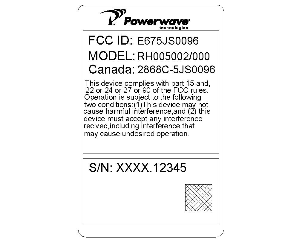
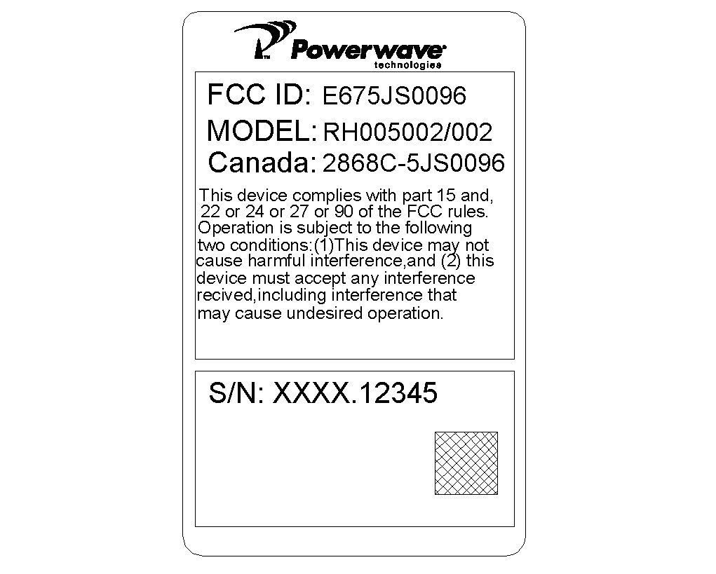
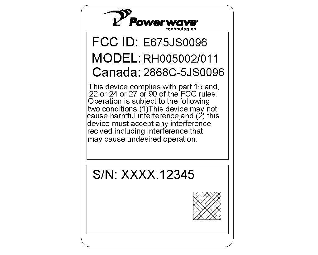
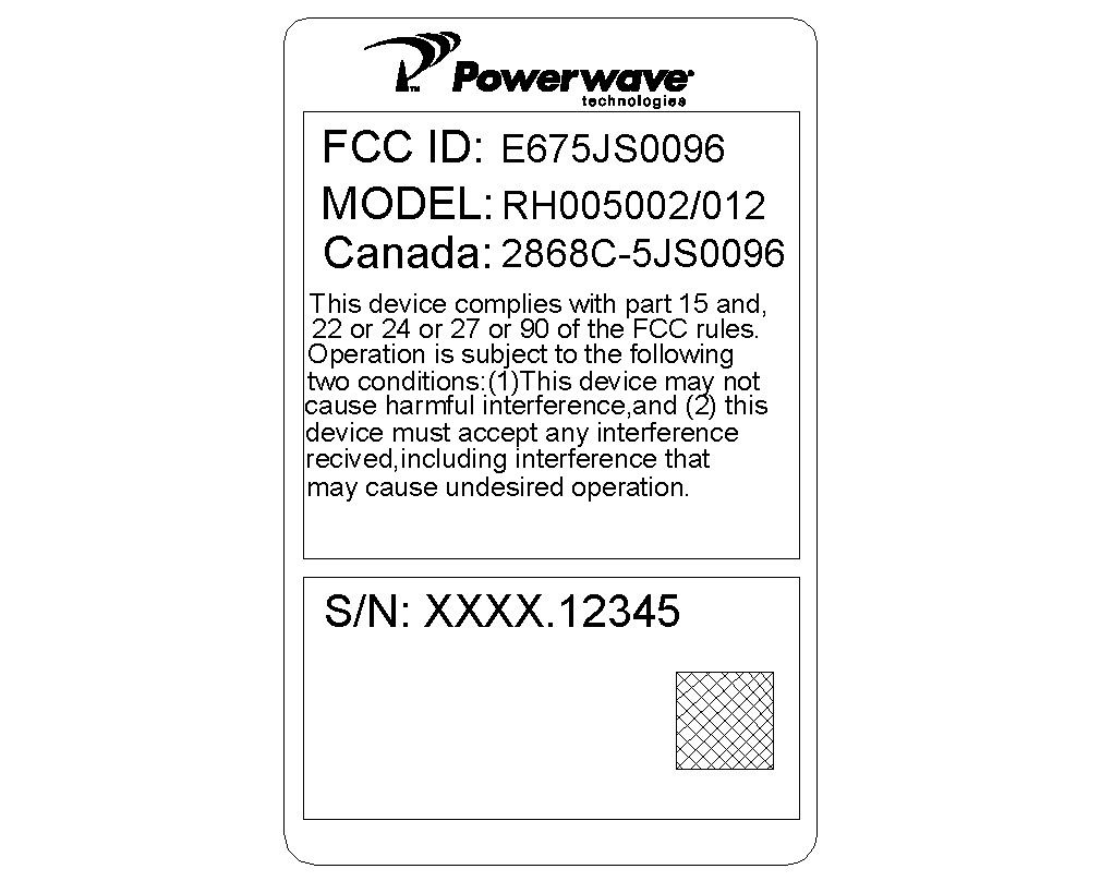
Document Text
Text extracted from the exhibit documents filed with the FCC. Open a document above to read the original.
Users Manual
044-05251 Rev A November 2007 High Power Wideband Radio Head (WRH-V) Installation and Service Manual © 2007 Powerwave Technologies Incorporated. All rights reserved. Powerwave Technologies and the Powerwave logo are registered trademarks. Powerwave Technologies Inc. reserves the right to make changes to documentation and equipment, including but not limited to component substitution and circuitry changes. Changes that impact this document may be subsequently incorporated in a later revision of this document. This Powerwave product is designed to operate within the Normal Operating (typical operating) ranges or con- ditions specified in this document. Operation of this equipment beyond the specified ranges in this document may cause (1) spurious emissions that violate regulatory requirements; (2) the equipment to be automatically removed from service when maximum thresholds are exceeded; or (3) the equipment to not perform in accor- dance with its specifications. It is the Operator's responsibility to ensure this equipment is properly installed and operated within Powerwave operating specifications to obtain proper performance from the equipment and to comply with regulatory requirements. The rated output power of a WRH-V it is for multiple carriers. As long as the composite power does not exceed the rated power (20W for North America), derating is not required for multiple carriers. For situations where regulatory requirements require reduced interference to adjacent band users, the rating would have to be reduced by 3 dB. This power reduction is to be by means of input power or gain reduction and not by an atten- uator at the output of the device. Input power is rated at 115/230VAC, 50/60Hz, and should be protected based on the power and fuse specifications in Chapter 5 of this manual. Power strips should, at a minimum, conform to this requirement to prevent equipment damage and possible overload. Federal Communications Commission (FCC) This equipment has been tested and found to comply with the limits for a Class A digital device, pursuant to CRF47 part 15 of the FCC rules. This equipment is also certified to CRF47 part 22 (cellular), part 24 (PCS) and part 90 (iDEN800 and iDEN900) of the FCC Rules depending on the band of operation. Changes or modifica- tions not expressly approved by Powerwave Technologies, Inc. for compliance could void the user’s authority to operate this equipment. These limits are designed to provide reasonable protection against harmful interfer- ence when the equipment is operated in a commercial environment. This equipment generates, uses, and can radiate radio frequency energy and, if not installed and used in accordance with the instruction manual, may cause harmful interference to radio communications. Operation of this equipment in a residential area is likely to cause harmful interference in which case the user will be required to correct the interference at his own expense. Industry Canadian Requirements All Powerwave apparatus introduced in the Canadian market meet all requirements of the Canadian Interfer- ence-Causing Equipment Regulations. The -20dB bandwidth at 1900 MHz band is 80 MHz. The -20dB band- width at the 850 MHz is 34 MHz. The output impedance of the unit referenced in this document is 50 Ohms. The -20dB bandwidth at IDEN 800MHz band is 26 MHz. The input signal is optical so input impedance requirements are not applicable. European Requirements The Powerwave WRH-V apparatus introduced in EU markets are certified to ESTI EN 300 609-4 (GSM900 and DCS1800) and ESTI EN 301 908-11 (WCDMA). Powerwave Technologies Inc., 1801 East St. Andrew Place, CA 92705 Santa Ana, USA. Phone +1 714 466 1000 – Fax +1 714 466 5800 – Internet www.powerwave.com High Power Wideband Radio Head (WRH-V)Warnings, Cautions, and Notes 044-05251 Rev Ai Warnings, Cautions, and Notes Warnings, Cautions, and Notes are found throughout this manual where applicable. The associated icons in warnings and cautions are used to quickly identify a potential condition that could result in the consequences described below if precautions are not taken. Notes clarify and provide additional information to assist the user. WARNING: The warning symbol means danger. You are in a situation that could cause bodily injury or death. Before you work on any equipment, be aware of the hazards involved with electrical and RF circuitry and be familiar with standard practices for preventing accidents. CAUTION: The caution symbol means the potential exists for equipment damage or loss of data. NOTE Notes contain helpful suggestions or references to material not covered in the document. Revision RecordHigh Power Wideband Radio Head (WRH-V) ii044-05251 Rev A Revision Record Revision Letter Date of ChangeReason for Change ANovember 2007New (original) 044-05251 Rev Aiii Table of Contents Chapter 1 - Product Description Introduction . . . . . . . . . . . . . . . . . . . . . . . . . . . . . . . . . . . . . . . . . . . . . . . . . . . . . . . . . . . . . . . . . . . . . . . .1-1 Scope of Manual . . . . . . . . . . . . . . . . . . . . . . . . . . . . . . . . . . . . . . . . . . . . . . . . . . . . . . . . . . . . . . . . . . . .1-1 Safety . . . . . . . . . . . . . . . . . . . . . . . . . . . . . . . . . . . . . . . . . . . . . . . . . . . . . . . . . . . . . . . . . . . . . . . . . . . .1-1 Human Exposure of RF Radiation . . . . . . . . . . . . . . . . . . . . . . . . . . . . . . . . . . . . . . . . . . . . . . . . . . .1-2 Antennas . . . . . . . . . . . . . . . . . . . . . . . . . . . . . . . . . . . . . . . . . . . . . . . . . . . . . . . . . . . . . . . . . . .1-2 Installation and Maintenance of Antenna Systems. . . . . . . . . . . . . . . . . . . . . . . . . . . . . . . . . . . .1-2 Radiation Exposure . . . . . . . . . . . . . . . . . . . . . . . . . . . . . . . . . . . . . . . . . . . . . . . . . . . . . . . . . . .1-2 Electrostatic Discharge (ESD). . . . . . . . . . . . . . . . . . . . . . . . . . . . .…
Text truncated - open the document above for the full version.
Block Diagram
Downlink WDM To OCM 1550nM Downlink 1310nM Uplink Downlink Uplink1 MCPA LNA TX RX TX0/RX0 Downlink WDM To OCM 1310nM Downlink 1550nM Uplink Downlink Uplink2 Uplink1 MCPA LNA LNA TX RX TX RX RX1 TX0/RX0 Downlink
Cover Letter(s)
Non-Conformities FCC ID: E675JS0096 (CKC CS Ref # E07-000129-FCC-01) The items listed below represent requests for information following review of this application for certification under United S tates (FCC) regulations. Further question may arise pending review of responses to these items. OK # Non-Conformity or Co mment Submitted Response Respondent / Date of Response 1 This equipment operates as a fiber to RF distribution system. Please clarify whether the equipment demodulates the RF signal. The optical transmitter on the FON board converts the electrical RF modulated signal to a 1310 or 1550nm optical RF modulated signal. 2 Pursuant to FCC guidelines for fiber distribution systems, the FCC requires use of equipment class TNB for this type of system. The application was filed with equipment class AMP. Please confirm whether this change is appropriate. Please correct the 731 form to TNB. 3
Cover Letter(s)
1801 E. St. Andrew Place, Santa Ana, CA 92705 USA www.powerwave.com +1.714.466.1000 Fax. +1.714.466.5800 Thursday, December 06, 2007 Federal Communications Commission Authorization and Evaluation Division 7435 Oakland Mills Road Columbia, MD 21046 Re: Request for Confidentiality In reference to the application under FCC ID: E675JS0096, and pursuant to Sections 0.457(d)(1)(ii) and 0.459 of the Commission's Rules, the Applicant hereby requests confidential treatment of the accompanying information as outlined below: Schematic Diagrams, Internal Photographs. The above materials contain trade secrets and proprietary information not customarily released to the public. The internal circuitry design uses proprietary techniques that are not known by the general public / industry. Powerwave Technologies customers have signed non-disclosure agreements. This product is only serviceable by Powerwave Technologies or a licensee. It is definitely not accessible by the general public in its deployment location(s). The public disclosure of these matters might be harmful to the Applicant and provide unjustified benefits to its competitors. The Applicant understands that pursuant to Rule 0.457(d)(1)(ii), disclosure of this Application and all accompanying documentation will not be made before the date of the Grant for this application. Sincerely, Charlotte Yu Reliability Engineer (714) 466-1732 (714) 466-5807 FAX [email protected]
External Photos
External Photos eut top eut bottom eut bottom2 eut_fr eut_back eut_left eut_right
Operational Description
DC Voltages - 87296 For the downlink or transmit path, the DC voltage into the PA is +27VDC±1VDC. The current consumption of the PA is typically 6.5 amperes at full power (43dBm/20W at the output antenna port). The PA has RF transistors that are class AB devices which pull current depending on the RF output power. The PA consumes 2 amperes typical with no RF output power. The driver amplifier (WBA) is supplied with 6.8VDC±0.5VDC. The WBA current consumption is constant with respect to output power as the RF devices are class A. The typical WBA current is 850mA.
Operational Description
Wideband Radio Heads (WRH) work as on-frequency amplifiers used to fill out uncovered areas in wireless mobile systems such as base station fringe areas, tunnels, business, convention centers, airports and industrial buildings. It receives, amplifies and transmits signals to/from a base station to/from mobile stations. The standard WRH is used for analog or digital systems, such as iDEN. It has a fiber optic donor port and a RF port for a service antenna (or RF cable) and is designed to be connected to a BTS via a BMU or OCM.
Parts List/Tune Up Info
044-05251 Rev A3-1 Chapter 3 Installation Introduction This chapter contains unpacking, inspection and installation instructions for installing and powering up the WRH. Site Survey Powerwave recommends that a site survey be performed prior to equipment ordering or installation. Performing a detailed site survey reduces or eliminates installation and turn-up delays. Pay particular attention to power plant capacity, cooling needs, floor space, and RF/DC cabling/breaker requirements. Cabinet dimensions and weights are listed in Chapter 5. Unpacking and Inspection This equipment has been operated, tested, and calibrated at the factory. Carefully open containers to remove equipment. Retain all packing material that can be reassembled in the event unit must be returned to the factory. Perform the following steps: ❑ Visually inspect equipment for damage that may have occurred during shipment. If possible, in the presence of the delivery person. ❑ Check for evidence of water damage, bent or warped chassis, loose screws or nuts, or extraneous packing material in connectors. If equipment is damaged, file a claim with the carrier once the extent of any damage is assessed. If equipment must be returned to factory, please contact factory for a Return Material Authorization (RMA), see Chapter 4. WRH-V Location The WRH-V is designed with a weather proof outdoor cabinet that can be mounted without any kind of shelter from rain, snow or hail. The same unit can be installed indoors. A preferable site for the WRH-V is a location free of obstructions, easily accessible and allows for proper air-flow and ventilation. If a WRH-V is installed outdoors and can be exposed to direct sunshine, it is essential that air circulates around the WRH-V with no obstacles. The operating temperature must not exceed 131°F (55°C). A shelter can be used to shade the WRH-V from direct sunshine. Never open a WRH-V when rain, snow, hail, high humidity or high winds are present unless some kind of temporary shelter can be erected. Mounting The WRH-V is easy to mount using the provided mounting bracket, which has 9/16-inch (14mm) holes for 3/8- inch (10mm) or 1/2-inch (12mm) fixing screws. Clamps with C-C measurements of 3.5-inch (90mm), 5.3-inch (135mm), 5.7-inch (144mm), 8.1-inch (205mm), 9.8-inch (250mm), and 11.8-inch (300mm) can be used as well. The vertical C-C measurement for these is 16.2-inch (411mm). There is a 9/16-inch (14mm) single hole in the middle of the mounting bracket, marked ‘A’ in the figure, which is intended for a locking screw to lock the bracket into place. MountingHigh Power Wideband Radio Head (WRH-V) 3-2044-05251 Rev A Figure 3-1 Mounting Bracket Normally, the WRH-V is mounted on a wall, pole, or mast. Figure 3-2 illustrates the installation of the mounting bracket on a wall using four fixing screws and a locking screw. Figure 3-2 Mounting Bracket Installation on Wall Figure 3-3 illustrates the installation of the mounting bracket on a pole using two 5.7-inch (144mm) U-shaped clamps and a locking screw. 90 135 144 205 250 300 Ø14 A 411 High Power Wideband Radio Head (WRH-V)Mounting 044-05251 Rev A3-3 Figure 3-3 Attaching the Bracket to a Pole Figure 3-4 illustrates a mast installation using two 11.8-inch (300mm) bar-shaped clamps and no locking screw. Figure 3-4 Attaching the Bracket to a Mast After installing the mounting bracket, hang the WRH-V on the upper supports, as illustrated in Figure 3-5. Tighten the upper and lower mounting screws to secure it into place using the 6mm hex socket wrench. Locking cylinders, used to prevent unauthorized removal of the repeater, can be inserted and locked with a ConnectionsHigh Power Wideband Radio Head (WRH-V) 3-4044-05251 Rev A key after the lower screws have been tightened. Make sure the donor antenna, directed towards the BTS antenna, and the service antenna, directed towards the area to be covered by the WRH, are mounted and installed properly. Figure 3-5 Attaching the WRH-V to the Bracket Connections This section describes general examples of how to connect the input and output ports on the WRH. Main Power and Grounding Local regulations need to be followed for the main power connection. WRH-Vs are approved in accordance with EN and UL/cUL regulations. This is, however, only valid if a classified power cord is used. For the WRH- V to meet these regulations you must select one of the following classified and approved cord types: ❑ EN – H 05 W5 - F HMR ❑ UL – AWM Style 2587 ❑ CSA– AWM 1 A/B 11 A/B For outdoor use, the power cord should meet at least IP65 encapsulation requirements. Do not turn the main power on until you are ready to commission the WRH. Fiber Optic and RF Connections Fiber optic and RF cable connections should be verified both internally and externally before powering up the equipment. This section illustrates the general internal connections of the WRH-V. Verify these connections with the as-built drawings and documents for your specific system configuration. Table 3-1 lists the steps to add the external connections to the WRH-V. WARNING: For WRH-Vs supplied from the main power source, the main outlet must be grounded. High Power Wideband Radio Head (WRH-V)Connections 044-05251 Rev A3-5 Table 3-1 Cable Connection Procedure WRH-V Figure 3-6 illustrates the cables and connections for the WRH-V. Figure 3-6 WRH-V Cable Connections StepAction 1Connect service antenna coaxial cable to left-outside DIN connection on cabinet 2Connect fiber optic cable from OCM or BMU to fiber optic cable demark on FOU 3Connect station ground to appropriate ground point in cabinet 4Mount main power plug to main power cord and insert into PSU 1550 1310 Power connection Fiber Optic Connection Service Antenna Connection Ground Points Optional ConnectionsHigh Power Wideband Radio Head (WRH-V) 3-6044-05251 Rev A Optional Connections Alarms Alarm signals from external sensors are received by an ALI or RCI which forwards them to the CU. The RCI is used if the WRH-V has an RC…
Text truncated - open the document above for the full version.
Test Report
Page 1 of 57 Report No.: CE07-182 POWERWAVE TECHNOLOGIES, INC. TEST REPORT FOR THE WIDE BAND RADIO HEAD, RH500020/211 & RH500020/212 FCC PART 15 SUBPART B SECTIONS 15.107 & 15.109 CLASS B, 15.111, FCC PART 90, RSS-131 ISSUE 2 (JULY 2003) AND RSS-GEN ISSUE 2 (JUNE 2007) TESTING DATE OF ISSUE: DECEMBER 6, 2007 PREPARED FOR: Powerwave Technologies, Inc. 1801 E. St. Andrew Place Santa Ana, CA 92705 PREPARED BY: Mary Ellen Clayton CKC Laboratories, Inc. 5046 Sierra Pines Drive Mariposa, CA 95338 P.O. No.: 116654 W.O. No.: 87286 Date of test: November 5-26, 2007 Report No.: FC07-102 This report contains a total of 57 pages and may be reproduced in full only. Partial reproduction may only be done with the written consent of CKC Laboratories, Inc. The results in this report apply only to the items tested, as identified herein. Page 2 of 57 Report No.: CE07-182 TABLE OF CONTENTS Administrative Information .............................................................................................3 Approvals .........................................................................................................................3 Summary of Results .........................................................................................................4 Conditions During Testing...............................................................................................4 Equipment Under Test (EUT) Description ......................................................................5 Equipment Under Test .....................................................................................................5 Peripheral Devices ...........................................................................................................5 Temperature and Humidity During Testing.....................................................................6 FCC 2.1033(c)(3) User’s Manual ....................................................................................6 FCC 2.1033(c)(4) Type of Emissions ..............................................................................6 FCC 2.1033(c)(5) Frequency Range................................................................................6 FCC 2.1033(c)(6) Operating Power.................................................................................6 FCC 2.1033(c)(7) Maximum Power Rating ....................................................................6 FCC 2.1033(c)(8) DC Voltages .......................................................................................6 FCC 2.1033(c)(9) Tune-Up Procedure ............................................................................6 FCC 2.1033(c)(10) Schematics and Circuitry Description..............................................6 FCC 2.1033(c)(11) Label and Placement ........................................................................6 FCC 2.1033(c)(12) Submittal Photos ..............................................................................6 FCC 2.1033(c)(13) Modulation Information ...................................................................6 FCC 15.107 – AC Conducted Emissions.........................................................................7 FCC 15.109 – Radiated Emissions ..................................................................................21 FCC 15.111 – Antenna Power Conduction Limits for Receiver .....................................27 FCC 2.1033(c)(14)/2.1046/90.635(a) - RF Power Output...............................................29 RSS-131 Mean Output Power..........................................................................................30 FCC 2.1033(c)(14)/2.1049(i) – Input and Output Plots...................................................32 FCC 2.1033(c)(14)/2.1051/90.691(a)(2) - Spurious Emissions at Antenna Terminal ....36 FCC 2.1033(c)(14)/2.1053/90.691(a)(2) - Field Strength of Spurious Radiation ...........41 Block Edge.......................................................................................................................45 Intermodulation................................................................................................................47 99% Bandwidth................................................................................................................50 RSS-131 Gain Linearity...................................................................................................53 Page 3 of 57 Report No.: CE07-182 ADMINISTRATIVE INFORMATION DATE OF TEST: November 5-26, 2007DATE OF RECEIPT: November 5, 2007 REPRESENTATIVE: Charlotte Yu MANUFACTURER: Powerwave Technologies, Inc. 1801 E. St. Andrew Place Santa Ana, CA 92705 TEST LOCATION: CKC Laboratories, Inc. 110 Olinda Place Brea, CA 92823 FREQUENCY RANGE TESTED: 9 kHz-9 GHz TEST METHOD: ANSI C63.4 (2003), FCC Part 90, RSS-131 Issue 2 (July 2003) and RSS- GEN Issue 2 (June 2007) PURPOSE OF TEST: To perform the testing of the Wide Band Radio Head, RH500020/211 with the requirements for FCC Part 15 Subpart B Sections 15.107 and 15.109 Class B, FCC Part 90 and RSS-131 devices. APPROVALS QUALITY ASSURANCE:TEST PERSONNEL: Steve Behm, Director of Engineering ServicesEddie Wong, EMC Engineer Page 4 of 57 Report No.: CE07-182 SUMMARY OF RESULTS TestSpecification/MethodResults Mains Conducted EmissionsFCC Part 15 Section 15.107 Class BPass Radiated EmissionsFCC Part 15 Section 15.109 Class BPass Antenna PowerFCC Part 15 Section 15.111Pass RF Power OutputFCC Part 90.635(a)Pass Mean Output PowerRSS-131 Section 4.3Pass Input and Output PlotsFCC Part 90Pass Spurious Emissions at Antenna Terminal FCC Part 90.691(a)(2)Pass Field Strength of Spurious Radiation FCC Part 90.691(a)(2)Pass Block EdgeFCC Part 90Pass IntermodulationFCC Part 90Pass 99% BandwidthFCC Part 90Pass Gain LinearityRSS-131 Section 6.1Pass CONDITIONS DURING TESTING No modifications to the EUT were necessary during testing. Page 5 of 57 Report No.: CE07-182 EQUIPMENT UNDER TEST (EUT) DESCRIPTION The customer d…
Text truncated - open the document above for the full version.
Test Setup Photos
Test Setup Photos cond em fr ac cond em bk ac cond en fr-dc cond en bk-dc cond em ant power cond em ant cond em _gain linear rad em fr ac rad em bk ac rad em fr dc rad em bk dc
Contact Information
Applicant
Jeff Dale(Principal Reliability Engineer)
Technical Contact
CKC Laboratories, Inc.Mary Ellen Clayton
[email protected]209-966-5240
5046 Sierra Pines Dr. · Mariposa · United States
Test Firm
CKC Laboratories, Inc.Steve Behm
Technical Specifications
| # | Rule Parts | Frequency Range | Power Output | Emission | Tolerance |
|---|---|---|---|---|---|
| 1 | 90 | 851 MHz - 869 MHz | 20 W | D7W | Amp |
Other Applications from Powerwave Technologies Inc

E675JS0123
Nov 03, 2011Multi-carrier RF Power Amplifier
Equipment Class
AMP - Amplifier
E675JS0120
Aug 26, 2010Nexus Dual Band Repeater
Equipment Class
TNB - Licensed Non-Broadcast Station Transmitter
E675JS0119
Aug 01, 2010Nexus Dual Band Repeater
Equipment Class
PCB - PCS Licensed Transmitter
E675JS0118
Jul 26, 2010Nexus Dual Band Repeater
Equipment Class
PCB - PCS Licensed Transmitter
E675JS0097
Jan 07, 2008RF Power Amplifier Frame
Equipment Class
AMP - Amplifier