E675JS0039SINGLE CHANNEL CELLULAR AMPLIFIER
Powerwave Technologies Inc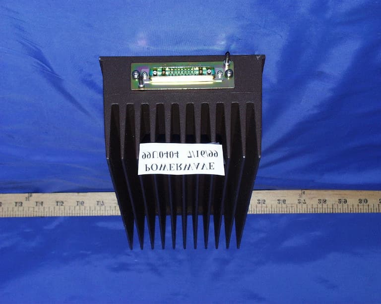
Click to zoom
Application Details
- Equipment Class
- AMP - Amplifier
- Date of Grant
- Oct 27, 1999
- Application Purpose
- Original Equipment
- Date of Application
- Aug 22, 1999
- Equipment Note
- SINGLE CHANNEL CELLULAR AMPLIFIER
- Frequency Range
- 869.00000000 - 894.00000000
- Company
- Powerwave Technologies Inc
- Country
- United States
Documents & Files
Document Text
Text extracted from the exhibit documents filed with the FCC. Open a document above to read the original.
Users Manual
OPERATING INSTRUCTIONS NTHX51AA Note: These operating instructions describe the procedure for turning on and off the amplifier output power using signal generators. This amplifier will be used with transmitters which have been or will be type accepted separately. The specific transmitter instruction book should be consulted for the correct method to use this amplifier with transmitters. 1. The input voltage range, applied to pin A2 of the connector, should be between 20.95 and 29.5 VDC. Pin A3 should be grounded. 2. A CMOS-level pulse (V h > 3.5 VDC, V l < 0.5 VDC) of frequency greater than 1 Hz must be applied to pin 5 (chip select input) of the connector. This prevents the watchdog timer circuitry from disabling the RF circuitry of the amplifier. 3. Pin 3 of the connector functions as the PA Enable. A CMOS high applied to Pin 3 enables the RF amplifier. CMOS low disables the amplifier. 4. The RF input is Pin A4. The output is Pin A1. 5. Pins 10, 15, and 17 should be connected to ground 6. To turn on the amplifier, first apply the DC voltage within the range specified above (25.15 VDC nominal. 7. Turn on the pulse to the chip select line (Pin 5). 8. Turn on the PA Enable (Pin 3). 9. For full rated output power (+47.5 dBm), the gain range may be from 23.5 to 27.0 dB. Increase the input power to the amplifier until the desired output power, monitored at the output connector, is reached. 10. The gain may change up to 0.5 dB as the amplifier temperature stabilizes after turn-on. Let the amplifier warm up for 10-30 minutes, then re-adjust the power to compensate for the gain change. 11. The amplifier is now operational. 12. Additional functions are available through the digital control circuitry. They are not necessary for turning on the amplifier and obtaining the desired signal, but they do communicate information to the Transmit/Receive Unit (TRU). Since these functions are controlled by the TRU, instructions for using these functions are contained in the specific TRU manuals, not the amplifier manual. a. Pins 8 and 9 are serial data lines accessing the EEPROM and digital control circuit. b. Pin 4 is used for the system clock. The TRU will provide a 24.3 kbits/s signal when performing an EEPROM read, and 9.72 kHz when clocking in the address and clocking out the data for A/D operations. c. Pin 6 is a CMOS input for selecting either the A/D converter or the EEPROM for the desired communications. d. Pin 11 is connected to the alarm LED anode. The TRU determines whether an alarm condition exists. e. Pin 12 is connected to the alarm LED cathode. f. Pin 13 is used for EEPROM register protection. g. Pins 14 and 16 are not used. SPECIFICATIONS ParameterSpecification Operating Frequency869 to 894 MHz Rated Output Power +47.5 dBm (56 Watts) Gain at Full Power 23.5 to 27.0 dB Input Voltage Range20.95 to 29.5 VDC ChannelingControlled by transmitter Modes of TransmissionAMPS Voice Mode AMPS Supervisory Audio Tone AMPS Wideband Data TDMA CDPD Type of ModulationNot applicable (performed by transmitter) Occupied Bandwidth and Emissions Designators Emissions TypeAmplitude Frequency Removed from Carrier AMPS Voice Mode (F8W)-26 dBc20 kHz to 45 kHz -60 dBc> 45 kHz AMPS Supervisory Audio Tone-26 dBc20kHz to 45 kHz (F8W)-60 dBc> 45 kHz AMPS Wideband Data (F1D)-26 dBc20 kHz to 45 kHz -45 dBc45 kHz to 90 kHz -60 dBc> 90 kHz TDMA Mode (DXW)-26 dBc15 to 45 kHz -45 dBc45 to 75 kHz -60 dBc> 75 kHz CDPD Mode (FXW)-26 dBc15 to 45 kHz -45 dBc45 to 75 kHz -60 dBc> 75 kHz
ID Label/Location Info
Proposed FCC ID Label Location Applicant : Powerwave Technologies, Inc. FCC ID:E675JS0039 FCC ID LABEL AREA
Test Report
FCC CFR47 PART 22 SUBPART H CERTIFICATION TEST REPORT FOR SINGLE CHANNEL CELLULAR AMPLIFIER MODEL : SCA9125-50 FCC ID: E675JS0039 REPORT NUMBER: 99U0404 ISSUE DATE: JULY 14, 1999 Prepared for POWERWAVE TECHNOLOGIES, INC. 2026 McGAW AVENUE IRVINE, CA 92614 Prepared by COMPLIANCE CERTIFICATION SERVICES, INC. 1366 BORDEAUX DRIVE SUNNYVALE, CA 94089, USA TEL: (408) 752-8166 FAX: (408) 752-8168 REPORT NO: 99U404 DATE:JULY 14, 1999 FCC ID: E675JS0039 EUT: SINGLE CHANNEL CELLULAR AMPLIFIER 0 COMPLIANCE CERTIFICATION SERVICESDOCUMENT NO:CCSUP4031A 1366 BORDEAUX DRIVE SUNNYVALE, CA 94089 USA TEL:(408) 752-8166 FAX:(408) 752-8168 This report shall not be reproduced except in full, without the written approval of CCS. TABLE OF CONTENTS PAGE 1.FCC CERTIFICATION INFORMATION..................................................................................................... 1 2.TEST FACILITY .............................................................................................................................................. 4 3.ACCREDITATION AND LISTING................................................................................................................ 4 4.MEASUREMENT INSTRUMENTATION .................................................................................................... 4 5.MEASURING INSTRUMENT CALIBRATION........................................................................................... 4 6.UNITS OF MEASUREMENT ......................................................................................................................... 4 7.EQUIPMENT MODIFICATIONS .................................................................................................................. 5 8.TEST EQUIPMENT LIST ............................................................................................................................... 6 9.EUT SETUP PHOTOS ..................................................................................................................................... 7 10.EXTERNAL I/O CABLE CONSTRUCTION DESCRIPTION ................................................................. 10 11.CONFIGURATION BLOCK DIAGRAM .................................................................................................... 12 12.PART 2: CERTIFICATION TEST REQUIREMENT: .............................................................................. 13 SECTION 2.1046: RF POWER OUTPUT ............................................................................................................ 13 SECTION 2.1047: MODULATION CHARACTERISTICS................................................................................. 15 SECTION 2.1049: OCCUPIED BANDWIDTH ................................................................................................... 16 SECTION 2.1051: SPURIOUS EMISSION AT ANTENNA TERMINALS........................................................ 26 SECTION 2.1053: FIELD STRENGTH OF SPURIOUS RADIATION............................................................... 36 SECTION 2.1055: FREQUENCT STABILITY .................................................................................................... 40 REPORT NO: 99U0404DATE:JULY 14, 1999FCC ID: E675JS0039 EUT: SINGLE CHANNEL CELLULAR AMPLIFIER 1 COMPLIANCE CERTIFICATION SERVICESDOCUMENT NO:CCSUP4031A 1366 BORDEAUX DRIVE SUNNYVALE, CA 94089 USA TEL:(408) 752-8166 FAX:(408) 752-8168 This report shall not be reproduced except in full, without the written approval of CCS. 1.FCC CERTIFICATION INFORMATION The following information is in accordance with FCC Rules, 47CFR Part2, Subpart J, Sections 2.1033 – 2.1055. 2.1033(c)(1) Applicant:POWERWAVE TECHNOLOGIES, INC. 2026 McGAW AVENUE IRVINE, CA 92614 Contact person: Robert Biedka Telephone number:(949) 757-6605 2.1033(c)(2)FCC ID: E675JS0039 2.1033(c)(3)Instructions/Installation Manual Refer to Attachment: User’s Manual. 2.1033(c)(4)Type of emissions DXW (TDMA) 2.1033(c)(5)Frequency Range 869 – 894 MHz 2.1033(c)(6)Range of Operation Power 55 Watts (47.4 dBm) 2.1033(c)(7)Maximum Power Rating Section 22.913(a); Maximum ERP. The effective radiated power (ERP) of base transmitters and cellular repeaters must not exceed 500 Watts. 2.1033(c)(8)Applied voltage and currents into the final transistor elements 24.5 Vdc @ 3 amps 2.1033(c)(9)Tune-up/Optimizations Procedure Refer to user’s manual REPORT NO: 99U0404DATE:JULY 14, 1999FCC ID: E675JS0039 EUT: SINGLE CHANNEL CELLULAR AMPLIFIER 2 COMPLIANCE CERTIFICATION SERVICESDOCUMENT NO:CCSUP4031A 1366 BORDEAUX DRIVE SUNNYVALE, CA 94089 USA TEL:(408) 752-8166 FAX:(408) 752-8168 This report shall not be reproduced except in full, without the written approval of CCS. 2.1033(c)(10) Complete Circuit Diagrams and Functional Diagram Refer to Schematics, Block Diagram and Parts list. Confidentiality is requested for these items. 2.1033(c)(10a) Means for Frequency Stabilization Not Applicable. Eut is a power amplifier 2.1033(c)(10b) Means for Suppressing of Spurious radiation. Manufacture will provide an external filter, which will be installed at the output of Eut’s antenna terminal, to attenuate any harmonics and spurious emission. Please refer to external filter specification. 2.1033(c)(10c) Means for Limiting Modulation. Not Applicable. Eut is a power amplifier. 2.1033(c)(10d) Means for Limiting Power. External Power Control 2.1033(c)(11) Equipment Identification A drawing of the equipment identification nameplate appears in file titled: PROPOSED FCC ID LABEL FORMAT. 2.1033(c)(12) Photographs Photographs of the equipment, internal and external views, are found in the Attachment: Eut Photographs. 2.1033(c)(13) Description of Digital Modulation Techniques TDMA (π/4 DQPSK) 2.1033(c)(14) Standard Test Condition The power amplifier was tested under the following conditions. DC Supply Voltage: 25.47Vdc AC Supply Voltage: 120Vac, 60Hz The amplifier was aligned and tuned up according to manufacturer’s alignment procedure, prior to testing…
Text truncated - open the document above for the full version.
Test Report
FCC CFR47 PART 22 SUBPART H CERTIFICATION TEST REPORT AMENDMENT FOR SINGLE CHANNEL CELLULAR AMPLIFIER TESTED WITH ADDITIONAL MODULATION TYPES CDPD AND AMPS ( INCLUDING VOICE, VOICE +SAT, WIDEBAND DATA) MODEL: SCA9125-50 FCC ID: E675JS0039 REPORT NUMBER: 99U0404 ISSUE DATE: SEPTEMBER 14, 1999 Prepared for POWERWAVE TECHNOLOGIES, INC. 2026 McGAW AVENUE IRVINE, CA 92614 Prepared by COMPLIANCE CERTIFICATION SERVICES, INC. 1366 BORDEAUX DRIVE SUNNYVALE, CA 94089, USA TEL: (408) 752-8166 FAX: (408) 752-8168 PROJECT NO:99U0404-1DATE:09/14/1999FCC ID:E675JS0039 EUT: SINGLE CHANNEL AMPLIFIER WITH CDPD, AMPS (VOICE, VOICE + SAT, WIDEBAND DATA) Page No: 1 COMPLIANCE CERTIFICATION SERVICESDOCUMENT NO:CCSUP4031A 1366 BORDEAUX DRIVE SUNNYVALE, CA 94089 USA TEL:(408) 752-8166 FAX:(408) 752-8168 This report shall not be reproduced except in full, without the written approval of CCS. TABLE OF CONTENTSPAGE FCC PART 2 CERTIFICATION ADDITIONAL TEST RESULTS:......................................................3 SECTION 2.1046: RF POWER OUTPUT.................................................................................................3 SECTION 2.1049: OCCUPIED BANDWIDTH........................................................................................5 SECTION 2.1051: SPURIOUS EMISSION AT ANTENNA TERMINAL.............................................8 Attachment : • Section 2.1046 plots from 1 to 4 • Section 2.1049 plots from 5 to 27 • Section 2.1051 plots from 28 to 35 PROJECT NO:99U0404-1DATE:09/14/1999FCC ID:E675JS0039 EUT: SINGLE CHANNEL AMPLIFIER WITH CDPD, AMPS (VOICE, VOICE + SAT, WIDEBAND DATA) Page No: 2 COMPLIANCE CERTIFICATION SERVICESDOCUMENT NO:CCSUP4031A 1366 BORDEAUX DRIVE SUNNYVALE, CA 94089 USA TEL:(408) 752-8166 FAX:(408) 752-8168 This report shall not be reproduced except in full, without the written approval of CCS. AMENDMENT BACKGROUND: In reference to our RF power amplifier, proposed FCC ID No. E67 5JS0039, the reason the additional modulation types were not included in the original filing, but are being appended later, results from a clarification by our customer, Nortel Networks, regarding how the amplifier will be used. This amplifier is intended to be used in two types of dual mode transmitter systems, which can be selected to operate in the following modes: 1) Transmitter Type 1:TDMA or AMPS (including Voice, Voice + SAT, and Wideband Data) 2) Transmitter Type 2:TDMA or CDPD Only 1 mode can be selected at a time, and the amplifier is used with only one carrier. Powerwave's understanding at the time of the original testing was that the amplifiers would only be used with TDMA modulation. Nortel uses a software interface with their transmit/receive unit to select which type of signal is transmitted. This selection is completely independent of the amplifier. AMENDMENT REQUESTED BY: Clinton Lawrence. Telephone no: ( 916 ) 985-1244 Report prepared by : Mike Kuo / Compliance Certification Services PROJECT NO:99U0404-1DATE:09/14/1999FCC ID:E675JS0039 EUT: SINGLE CHANNEL AMPLIFIER WITH CDPD, AMPS (VOICE, VOICE + SAT, WIDEBAND DATA) Page No: 3 COMPLIANCE CERTIFICATION SERVICESDOCUMENT NO:CCSUP4031A 1366 BORDEAUX DRIVE SUNNYVALE, CA 94089 USA TEL:(408) 752-8166 FAX:(408) 752-8168 This report shall not be reproduced except in full, without the written approval of CCS. FCC PART 2 CERTIFICATION ADDITIONAL TEST RESULTS: SECTION 2.1046: RF POWER OUTPUT Equipment used. HP Spectrum Analyzer/8593EM Narda 30dB Attenuator Flexco low loss cables, 9ft. (Loss: 0.85 dB/ft @ 26GHz) HP RF Communication test set/8920B Transmitter Unit/TRU II NNTM53101DYE Laptop computer. TEST SETUP: Minimum Requirement: Section 22.913(a) Maximum ERP: The effective radiated power (ERP) of base transmitters and cellular repeaters must not exceed 500 Watts. The ERP of mobile transmitters and auxiliary test transmitters must not exceed 7 Watts. Test Procedure: Turn on the EUT and connected the transmitter antenna output to spectrum analyzer using a low loss cable. RES b/w. was set to 30kHz and adjusted spectrum analyzer to center frequency at the highest amplitude appearing on spectral display. Then set spectrum analyzer frequency span to show signal on spectrum analyzer. This test was done for low, middle, and high channel both for analog and digital modulations. Eut is a cellular amplifier 30dB attenuator Laptop Spectrum analyzer TX UNIT Or HP8920B PROJECT NO:99U0404-1DATE:09/14/1999FCC ID:E675JS0039 EUT: SINGLE CHANNEL AMPLIFIER WITH CDPD, AMPS (VOICE, VOICE + SAT, WIDEBAND DATA) Page No: 4 COMPLIANCE CERTIFICATION SERVICESDOCUMENT NO:CCSUP4031A 1366 BORDEAUX DRIVE SUNNYVALE, CA 94089 USA TEL:(408) 752-8166 FAX:(408) 752-8168 This report shall not be reproduced except in full, without the written approval of CCS. Test Result: Power was measured with Spectrum analyzer. Plots of Voice and Wideband modulation power output are included. CDPD Modulation power was measured by customer, which came to be +47 dBm. AMPS MODE PLOT NUMBER LOW: 50Watts (47 dBm) 1 HIGH: 2 WIDEBAND MODE PLOT NUMBER LOW: 3 HIGH: 4 PROJECT NO:99U0404-1DATE:09/14/1999FCC ID:E675JS0039 EUT: SINGLE CHANNEL AMPLIFIER WITH CDPD, AMPS (VOICE, VOICE + SAT, WIDEBAND DATA) Page No: 5 COMPLIANCE CERTIFICATION SERVICESDOCUMENT NO:CCSUP4031A 1366 BORDEAUX DRIVE SUNNYVALE, CA 94089 USA TEL:(408) 752-8166 FAX:(408) 752-8168 This report shall not be reproduced except in full, without the written approval of CCS. SECTION 2.1049: OCCUPIED BANDWIDTH Equipment used. HP Spectrum Analyzer/8593EM Narda 30dB Attenuator Flexco low loss cables, 9ft. (Loss: 0.85 dB/ft @ 26GHz) HP RF Communication test set/8920B Transmitter Unit/TRU II NNTM53101DYE Laptop computer. TEST SETUP: Minimum Requirement: AMPS: (A) For voice modulation 22.917(B) F3E/F3D: On any frequency removed from the carrier by greater than 20 kHz up to and including 45 kHz: At least 26 dBc; 2. On any frequency removed from the carrier frequency by greater than 45 kHz up to the first multiple of the carrier frequenc…
Text truncated - open the document above for the full version.
Contact Information
Applicant
Jeff Dale(Principal Reliability Engineer)
Technical Contact
COMPLIANCE ENGINEERING SERVICES, INC.MIKE KUO
[email protected]4087528166
1366 BORDEAUX DRIVE · SUNNYVALE, California · United States
Non-Technical Contact
COMPLIANCE ENGINEERING SERVICES, INC.MIKE KUO
[email protected]4087528166
Test Firm
Compliance Certification Services IncSteve Cheng
Technical Specifications
| # | Rule Parts | Frequency Range | Power Output | Emission | Tolerance |
|---|---|---|---|---|---|
| 4 | 22H | 869 MHz - 894 MHz | 55 W | F1D | % |
Other Applications from Powerwave Technologies Inc

E675JS0123
Nov 03, 2011Multi-carrier RF Power Amplifier
Equipment Class
AMP - Amplifier
E675JS0120
Aug 26, 2010Nexus Dual Band Repeater
Equipment Class
TNB - Licensed Non-Broadcast Station Transmitter
E675JS0119
Aug 01, 2010Nexus Dual Band Repeater
Equipment Class
PCB - PCS Licensed Transmitter
E675JS0118
Jul 26, 2010Nexus Dual Band Repeater
Equipment Class
PCB - PCS Licensed Transmitter
E675JS0096
Jan 10, 2008Wideband Radio Head
Equipment Class
TNB - Licensed Non-Broadcast Station Transmitter