E675JS0041PCS LINEAR POWER AMPLIFIER
Powerwave Technologies Inc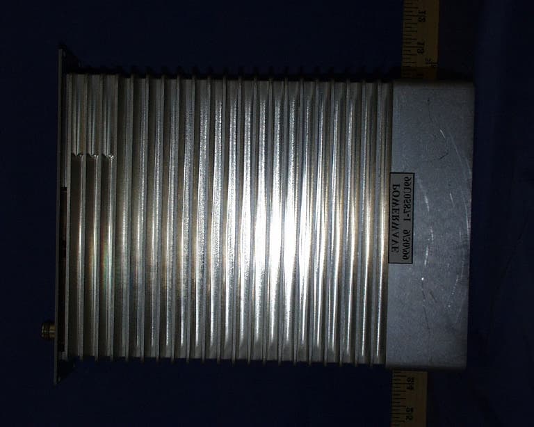
Click to zoom
Application Details
- Equipment Class
- AMP - Amplifier
- Date of Grant
- Feb 22, 2000
- Application Purpose
- Original Equipment
- Date of Application
- Dec 16, 1999
- Equipment Note
- PCS LINEAR POWER AMPLIFIER
- Frequency Range
- 1930.00000000 - 1990.00000000
- Company
- Powerwave Technologies Inc
- Country
- United States
Documents & Files
Document Text
Text extracted from the exhibit documents filed with the FCC. Open a document above to read the original.
Users Manual
OPERATING INSTRUCTIONS SPA9325-30 Note: These operating instructions describe the procedure for turning on and off the amplifier output power using signal generators. This amplifier will be used with transmitters which have been or will be certified separately. The specific transmitter instruction book should be consulted for the correct method to use this amplifier with transmitters. 1. The input voltage range, applied to pin A1 of the DC input connector, should be between –36VDC and –57 VDC. Pin A2 and A3 of the connector should be grounded. 2. Pin 5 of the Data I/O connector should be grounded to enable operation of the amplifier without the data interface. Pins 1, 2, 11, and 12 on the Data I/O connector are connected to ground. Operation with the Data I/O interface can only be performed using the transmitter software. See the transmitter manual for instructions. 3. Connect the RF signal generator to the RF input port. 4. Connect the RF output port to the measurement equipment. Make sure the measurement equipment is capable of handling 30 watts, or use a power attenuator or directional coupler to attenuate the signal to a level the equipment can handle. 5. To turn on the amplifier, first apply the DC voltage with the specified range (-48 VDC nominal). 6. Apply RF power from the signal generator. Adjust the RF input power until the desired RF output power is achieved. The amplifier’s maximum RF output power rating is 30 watts (+44.8 dBm) 7. The gain may change up to 0.5 dB as the amplifier temperature stabilizes after turn-on. Let the amplifier warm up for 10-30 minutes, then re-adjust the power to compensate for the gain change. 8. The amplifier is now operational. SPECIFICATIONS ParameterSpecification Operating Frequency1930 to 1990 MHz Rated Output Power +44.8 dBm (30 Watts) Gain at Full Power 48 +/- 1 dB Input Voltage Range-36 to –57 VDC Maximum DC Power Consumption220 Watts ChannelingControlled by transmitter Modes of TransmissionGSM (Gaussian Minimum Shift Keying) Type of ModulationNot applicable (performed by transmitter) Occupied Bandwidth and Emissions Designators Emissions TypeAmplitude Frequency Removed from Carrier GSM (300KGXW)-30 dBc200 kHz -33 dBc250 kHz -60 dBc400 kHz -70 dBc600 kHz -73 dBc1200 kHz -75 dBc1800 kHz -80 dBc6000 kHz
Test Report
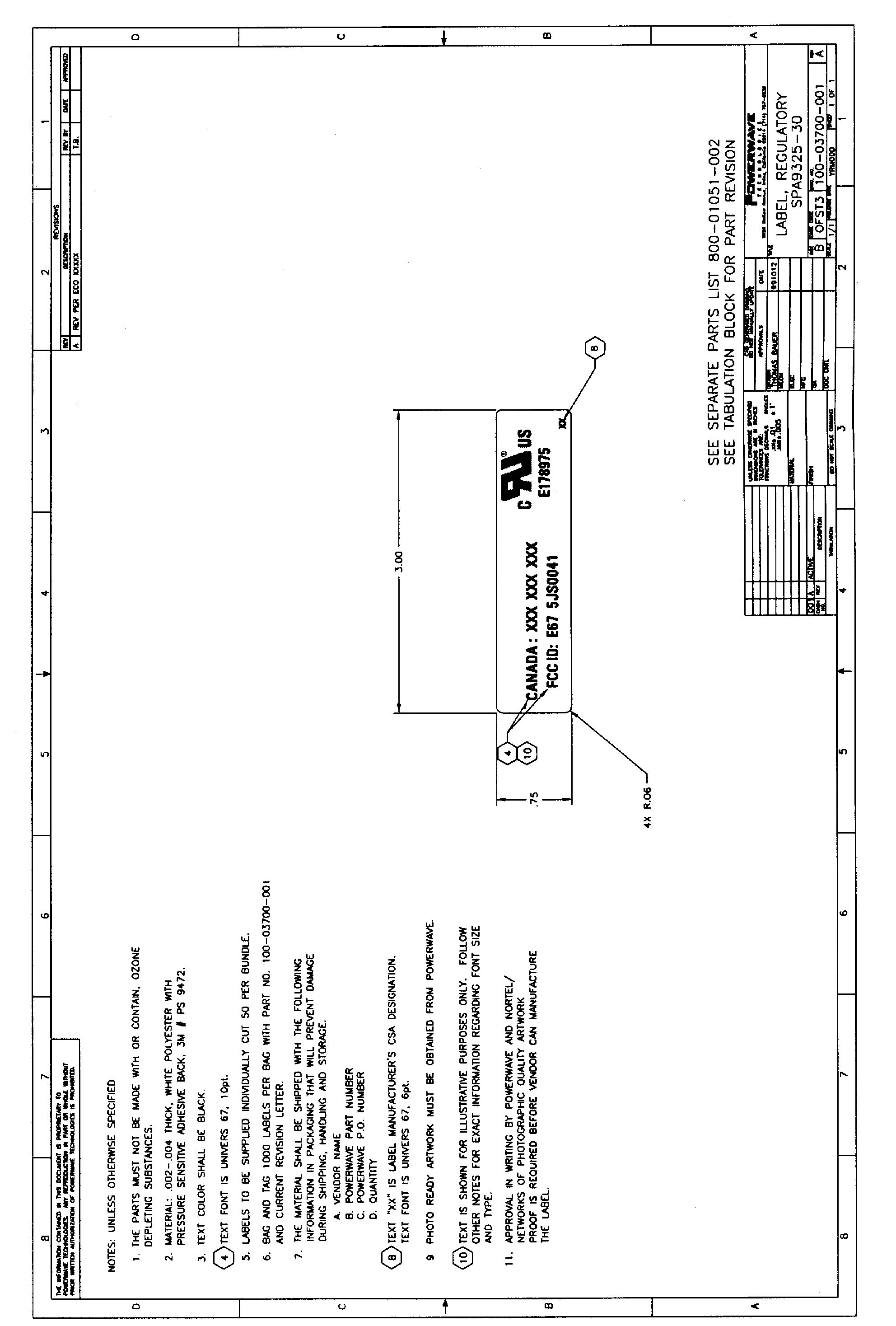
FCC CFR47 PART 24 SUBPART E BROADBAND PCS TEST REPORT FOR PCS LINEAR POWER AMPLIFIER MODEL: SPA9325-30 FCC ID: E675JS0041 REPORT NUMBER: 99U0587 ISSUE DATE: SEPTEMBER 28, 1999 Prepared for POWERWAVE TECHNOLOGIES, INC. 2026 McGAW AVENUE IRVINE, CA 92614 Prepared by COMPLIANCE CERTIFICATION SERVICES, INC. d.B.a. COMPLIANCE CERTIFICATION SERVICES 1366 BORDEAUX DRIVE SUNNYVALE, CA 94089, USA TEL: (408) 752-8166 FAX: (408) 752-8168 REPORT NO: 99U0587 DATE: SEPTEMBER 28, 1999 FCC ID: E675JS0041 EUT: PCS LINEAR POWER AMPLIFIER 1 COMPLIANCE CERTIFICATION SERVICESDOCUMENT NO:CCSUP4031A 1366 BORDEAUX DRIVE SUNNYVALE, CA 94089 USA TEL:(408) 752-8166 FAX:(408) 752-8168 This report shall not be reproduced except in full, without the written approval of CCS. TABLE OF CONTENTS PAGE 1.FCC CERTIFICATION INFORMATION ...................................................................................................... 2 2.TEST RESULT SUMMARY FOR PART 15. .................................................................................................. 5 3.FCC PART 2 CERTIFICATION TEST RESULTS:.......................................................................................6 SECTION 2.1046: RF POWER OUTPUT.................................................................................................................. 6 SECTION 2.1047: MODULATION CHARACTERISTICS...................................................................................... 8 SECTION 2.1049: OCCUPIED BANDWIDTH......................................................................................................... 9 SECTION 2.1051: SPURIOUS EMISSION AT ANTENNA TERMINAL............................................................. 11 SECTION 2.1053: FIELD STRENGTH OF SPURIOUS RADIATION................................................................. 14 SECTION 2.1055: FREQUENCY STABILITY....................................................................................................... 16 4.EUT SETUP PHOTOS ..................................................................................................................................... 18 ATTACHMENT 1. EUT PHOTOGRAPHS 2. INSTALLATION & SERVICE MANUAL 3. ADDENUM 1 SCHEMATIC & PARTS LISTS 4. PROPOSED FCC ID LABEL FORMAT REPORT NO: 99U0587 DATE: SEPTEMBER 28, 1999 FCC ID: E675JS0041 EUT: PCS LINEAR POWER AMPLIFIER 2 COMPLIANCE CERTIFICATION SERVICESDOCUMENT NO:CCSUP4031A 1366 BORDEAUX DRIVE SUNNYVALE, CA 94089 USA TEL:(408) 752-8166 FAX:(408) 752-8168 This report shall not be reproduced except in full, without the written approval of CCS. 1.FCC CERTIFICATION INFORMATION The following information is in accordance with FCC Rules, 47CFR Part2, Subpart J, Sections 2.1033 – 2.1055. 2.1033(c)(1) Applicant:POWERWAVE TECHNOLOGIES, INC. 2026 McGAW AVENUE IRVINE, CA 92614 Contact person: Robert Biedka Telephone number:(714) 757-6605 2.1033(c)(2)FCC ID: E675JS0041 2.1033(c)(3)Instructions/Installation Manual Refer to Attachment: Installation and Service manual. 2.1033(c)(4)Type of emissions 300K0GXW 2.1033(c)(5)Frequency Range Transmit: 1930 – 1990 MHz 2.1033(c)(6)Range of Operation Power 200mW to 30 W 2.1033(c)(7)Maximum Power Rating Section 24.232(a); Maximum ERP. The effective radiated power (ERP) of base transmitters must not exceed 100 Watts. 2.1033(c)(8)Applied voltage and currents into the final transistor elements 26 Vdc @ 2 amps 2.1033(c)(9)Tune-up/Optimizations Procedure Refer to Attachment: Installation and Service manual. REPORT NO: 99U0587 DATE: SEPTEMBER 28, 1999 FCC ID: E675JS0041 EUT: PCS LINEAR POWER AMPLIFIER 3 COMPLIANCE CERTIFICATION SERVICESDOCUMENT NO:CCSUP4031A 1366 BORDEAUX DRIVE SUNNYVALE, CA 94089 USA TEL:(408) 752-8166 FAX:(408) 752-8168 This report shall not be reproduced except in full, without the written approval of CCS. 2.1033(c)(10) Complete Circuit Diagrams and Functional Diagram Refer to Attachment: Schematics and Parts list. Confidentiality is requested for these items. 2.1033(c)(10a) Means for Frequency Stabilization Not Applicable. Eut is a power amplifier 2.1033(c)(10b) Means for Suppressing of Spurious radiation. Not applicable. 2.1033(c)(10c) Means for Limiting Modulation. Not Applicable. Eut is a power amplifier. 2.1033(c)(10d) Means for Limiting Power. Compression of the RF output power transistors. 2.1033(c)(11) Equipment Identification A drawing of the equipment identification nameplate appears under Attachment: PROPOSED FCC ID LABEL FORMAT. 2.1033(c)(12) Photographs Photographs of the equipment, internal and external views, are found in the Attachment: Eut Photographs. 2.1033(c)(13) Description of Digital Modulation Techniques Not Applicable. 2.1033(c)(14) Standard Test Condition The power amplifier was tested under the following conditions. DC Supply Voltage: 26Vdc AC Supply Voltage: 120Vac, 60Hz The amplifier was aligned and tuned up according to manufacturer’s alignment procedure, prior to testing. All data presented represents the worst case parameter being measured. REPORT NO: 99U0587 DATE: SEPTEMBER 28, 1999 FCC ID: E675JS0041 EUT: PCS LINEAR POWER AMPLIFIER 4 COMPLIANCE CERTIFICATION SERVICESDOCUMENT NO:CCSUP4031A 1366 BORDEAUX DRIVE SUNNYVALE, CA 94089 USA TEL:(408) 752-8166 FAX:(408) 752-8168 This report shall not be reproduced except in full, without the written approval of CCS. 2.1033Description of Various Base Station Configuration Not Applicable. TYPE OF EQUIPMENT:PCS LINEAR AMPLIFIER MEASUREMENT DISTANCE:(X) 3 METER ( ) 10 METER FCC RULES:PART 2, PART 15, PART 24 SUBPART E EQUIPMENT AUTHORIZATION PROCEDURE CERTIFICATION MODIFICATIONS MADE ON EUT YES NO DEVIATIONS FROM MEASUREMENT PROCEDURE YES NO The above equipment was tested by Compliance Certification Services for compliance with the requirements set forth in the FCC CFR 47, PART 2, PART 15 and PART 24. The results of testing in this report apply to the product/system which was tested only. Other similar equipment will not necessarily produce the same results due to production …
Text truncated - open the document above for the full version.
Contact Information
Applicant
Jeff Dale(Principal Reliability Engineer)
Technical Contact
COMPLIANCE ENGINEERING SERVICES, INC.MIKE KUO
[email protected]408-752-8166
1366 BORDEAUX DRIVE · SUNNYVALE, California · United States
Non-Technical Contact
COMPLIANCE ENGINEERING SERVICES, INC.MIKE KUO
[email protected]408-752-8166
Test Firm
Compliance Certification Services IncSteve Cheng
Technical Specifications
| # | Rule Parts | Frequency Range | Power Output | Emission |
|---|---|---|---|---|
| 1 | 24E | 1.93 GHz - 1.99 GHz | 30 W | GXW |
Other Applications from Powerwave Technologies Inc

E675JS0123
Nov 03, 2011Multi-carrier RF Power Amplifier
Equipment Class
AMP - Amplifier
E675JS0120
Aug 26, 2010Nexus Dual Band Repeater
Equipment Class
TNB - Licensed Non-Broadcast Station Transmitter
E675JS0119
Aug 01, 2010Nexus Dual Band Repeater
Equipment Class
PCB - PCS Licensed Transmitter
E675JS0118
Jul 26, 2010Nexus Dual Band Repeater
Equipment Class
PCB - PCS Licensed Transmitter
E675JS0096
Jan 10, 2008Wideband Radio Head
Equipment Class
TNB - Licensed Non-Broadcast Station Transmitter