E675JS0045Multicarrier PCS Power Amplifier
Powerwave Technologies Inc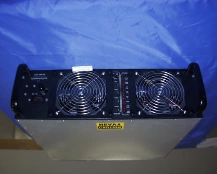
Click to zoom
Application Details
- Equipment Class
- AMP - Amplifier
- Date of Grant
- Jan 16, 2001
- Application Purpose
- Original Equipment
- Date of Application
- Oct 12, 2000
- Equipment Note
- Multicarrier PCS Power Amplifier
- Frequency Range
- 1930.00000000 - 1990.00000000
- Company
- Powerwave Technologies Inc
- Country
- United States
Documents & Files
Document Text
Text extracted from the exhibit documents filed with the FCC. Open a document above to read the original.
Users Manual
044-05077 Rev. A ii TABLE OF CONTENTS Par. Section 1 Page No. General Description No. 1-1Introduction............................................................................................................. 1-1 1-2General Description................................................................................................ 1-1 1-3Functional and Physical Specifications....................................................................... 1-1 1-4Equipment Changes................................................................................................. 1-1 1-5Ordering Information................................................................................................ 1-2 Section 2 Installation 2-1Introduction............................................................................................................. 2-1 2-2Electrical Service Recommendations......................................................................... 2-1 2-3Unpacking and Inspection......................................................................................... 2-1 2-4Installation Instructions............................................................................................. 2-2 2-5Amplifier Module Connectors.................................................................................... 2-2 2-5.1Amplifier Module Status, Alarm, Control, and Power Connector .................................. 2-3 2-5.2Amplifier Module RF Connector ................................................................................ 2-4 Section 3 Operating Instructions 3-1Introduction............................................................................................................. 3-1 3-2Location and Function of Amplifier Module Controls and Indicators .............................. 3-1 3-3Initial Start-Up and Operating Procedures ................................................................. 3-4 Section 4 Principles of Operation 4-1Introduction............................................................................................................. 4-1 4-2RF Input Signal........................................................................................................ 4-1 4-3RF Output Load...................................................................................................... 4-1 4-4System Functional Description.................................................................................. 4-1 4-5G3S-1900-80 Amplifier Module................................................................................. 4-1 4-5.1Main Amplifier ......................................................................................................... 4-3 4-5.2Error Amplifier......................................................................................................... 4-3 4-5.3Amplifier Monitoring ................................................................................................. 4-3 4-5.4Amplifier Module Cooling.......................................................................................... 4-4 4-6Power Distribution ................................................................................................... 4-4 4-7Intermodulation........................................................................................................ 4-4 4-7.1Two Tone Intermodulation........................................................................................ 4-4 4-7.2Multitone Intermodulation ......................................................................................... 4-4 4-8Alarms.................................................................................................................... 4-4 044-05077 Rev. A iii TABLE OF CONTENTS (Continued) Par. Section 5 Page No. Maintenance No. 5-1Introduction............................................................................................................. 5-1 5-2Periodic Maintenance............................................................................................... 5-1 5-3Test Equipment Required For Test ........................................................................... 5-1 5-4Cleaning Air Inlets/Outlets ........................................................................................ 5-2 5-5Performance Test.................................................................................................... 5-2 5-5.1Amplifier System Performance Test .......................................................................... 5-2 5-6Field Replaceable Parts and Modules....................................................................... 5-6 5-6.1G3S-1900-80 Power Amplifier Module...................................................................... 5-6 5-6.2Cooling Fans........................................................................................................... 5-6 Section 6 Troubleshooting 6-1Introduction............................................................................................................. 6-1 6-2Troubleshooting....................................................................................................... 6-1 6-3Return for Service Procedure ................................................................................... 6-1 6-3.1Obtaining an RMA ................................................................................................... 6-1 6-3.2Repackaging for Shipment ....................................................................................... 6-1 LIST OF ILLUSTRATIONS FigurePage No.No. 1-1G3S-1900-80 Amplifier............................................................................................ 1-3 2-1G3S-1900-80 Amplifier, Rear View........................................................................... 2-2 2-2DC and Logic Connector (on Rear of G3S-1900-80 Amplifier Module)......................... 2-3 2-3Amplifier RF Connector ......................................…
Text truncated - open the document above for the full version.
Users Manual
044-05077 Rev. A 2-1 INSTALLATION 2-1. INTRODUCTION This section contains installation recommendations, unpacking, inspection, and installation instructions for the multicarrier PCS amplifier. Carefully read all material in this section prior to equipment unpacking or installation. Also read and review the operating procedures in Section 3 prior to installing the equipment. It is important that the licensee perform these tasks correctly and in good faith. If applicable, carefully read Parts 73 and 74 of the Federal Communications Commission (FCC) rules to determine how they apply to your installation. DON'T TAKE CHANCES WITH YOUR LICENSE. 2-2. ELECTRICAL SERVICE RECOMMENDATIONS Powerwave Technologies recommends that proper AC line conditioning and surge suppression be provided on the primary AC input to the +27 Vdc power source. All electrical service should be installed in accordance with the National Electrical Code, any applicable state or local codes, and good engineering practice. Special consideration should be given to lightning protection of all systems in view of the vulnerability of most transmitter sites to lightning. Lightning arrestors are recommended in the service entrance. Straight, short ground runs are recommended. The electrical service must be well grounded. Each amplifier system should have its own circuit breaker, so a failure in one does not shut off the whole installation. Circuit breakers should be thermal type, capable of handling the anticipated inrush current, in a load center with a master switch. 2-3. UNPACKING AND INSPECTION This equipment has been operated, tested and calibrated at the factory. Only in the event of severe shocks or other mistreatment should any substantial readjustment be required. Carefully open the container(s) and remove the amplifier module(s). Retain all packing material that can be reassembled in the event that the unit must be returned to the factory. CAUTION Exercise care in handling equipment during inspection to prevent damage caused by rough or careless handling. Visually inspect the amplifier module for damage that may have occurred during shipment. Check for evidence of water damage, bent or warped chassis, loose screws or nuts, or extraneous packing material in the connector or fans. Inspect the rear panel connector for bent connector pins. If the equipment is damaged, a claim should be filed with the carrier once the extent of any damage is assessed. We cannot stress too strongly the importance of IMMEDIATE careful inspection of the equipment and the subsequent IMMEDIATE filing of the necessary claims against the carrier if necessary. If possible, inspect the equipment in the presence of the delivery person. If the equipment is damaged, the carrier is your first area of recourse. If the equipment is damaged and must be returned to the factory, write or phone for a return authorization. Powerwave may not accept returns without a return authorization. Claims for loss or damage may not be withheld from any payment to Powerwave, nor may any payment due be withheld pending the outcome thereof. WE CANNOT GUARANTEE THE FREIGHT CARRIER'S PERFORMANCE. Section 2 044-05077 Rev. A 2-2 2-4. INSTALLATION INSTRUCTIONS (Refer to figures 1-1 and 2-1) The G3S-1900-80 amplifier module is designed for installation in a subrack that permits access to the rear of the subrack for connection of DC power, RF, and monitor cables. To install the amplifier proceed as follows: 1. Install subrack in equipment rack and secure in place. 2. Connect antenna cable to rear of subrack. 3. Connect the transceiver output(s) to rear of subrack. 4. Connect alarms cable(s). WARNING Verify that all circuit breaker switches on the rear panel of the subrack are in the OFF position. Turn off external primary DC power before connecting DC power cables. 7. Connect positive primary power and negative primary power to the subrack. Tighten the subrack power connections. 8. Install the plug-in amplifier module(s) in the subrack. Verify that the latch is properly seated. 9. Check your work before applying DC voltage to the system. Make certain all connections are tight and correct. 10. Measure primary DC input voltage. DC input voltage should be +27 Vdc ±1.0 Vdc. If the DC input voltage is above or below the limits, call and consult Powerwave before you turn on your amplifier system. 11. Refer to section 3 for initial turn-on and checkout procedures. 2-5 AMPLIFIER MODULE CONNECTORS The amplifier has three connectors on the right rear of the module. The largest is a 21-pin male D-Sub combo which provides the status, alarm, control, and power connections. The smaller connectors are BMA female coaxial contacts from Radiall, which provide the RF connections. Refer to figure 2-1. Figure 2-1. G3S-1900-80 Amplifier, Rear View 044-05077 Rev. A 2-3 2-5.1. AMPLIFIER MODULE STATUS, ALARM, CONTROL, AND POWER CONNECTOR The amplifier has a separate remote alarm and control connector which may be used by the host system to monitor and control the individual amplifier modules. The status, alarm, control, and power connections on the amplifier connector are made through a 21-pin male D-Sub combo connector (figure 2-2) and are listed and described in table 2-1. Figure 2-2. DC and Logic Connector (on Rear of G3S-1900-80 Amplifier Module] Table 2-1. Amplifier Module DC and Logic Connector Definition PINFUNCTIONDESCRIPTION A1Power Input+27 Vdc (Power Contact) A2Power Input+27 Vdc (Power Contact) A3GroundGround (Power Contact) A4GroundGround (Power Contact) 1RS485 +TxDSerial Communication Data Out 2RS485 +RxDSerial Communication Data In 3Service LoopTTL input to Amp. Gnd. for special test mode (Note 1) 4MCPA Disabled (Summary Fault) TTL signal normally low indicates MCPA enabled. A high level indicates that the MCPA has been disabled. Over Power, Over Voltage takes one second to activate the signal. 5Mod Addr 0TTL input to Amp. Gnd. supplied by shelf to identify slot. 6Mod Addr 1TTL input to Amp. G…
Text truncated - open the document above for the full version.
Users Manual
044-05077 Rev. A 3-1 OPERATING INSTRUCTIONS 3-1. INTRODUCTION This section contains operating instructions for the multicarrier PCS amplifier system. 3-2. LOCATION AND FUNCTION OF AMPLIFIER MODULE CONTROLS AND INDICATORS Primary +27 Vdc power is applied to the amplifier via an 80-amp circuit breaker (ON-OFF) located on the left side of the amplifier front panel. The plug-in amplifier module RF control and indicators, located in the center of the amplifier front panel between the cooling fans, are shown in figure 3-1. The status and RF control functions are described in detail in table 3-1. The alarms are described in detail in table 3-2. Figure 3-1. G3S-1900-80 Amplifier Module RF Control and Indicators Section 3 044-05077 Rev. A 3-2 Table 3-1. Amplifier Module RF Control and Indicators Definition NAMEFUNCTION (Note: MCPA = Multicarrier Power Amplifier) +27VDC Indicator Green LED. When lit, indicates that the +27 Vdc supply is greater than +21 Vdc and less than +31 Vdc. If the +27 Vdc indicator goes out, the DC FAIL indicator will illuminate. This indicates that the +27 Vdc volt- age dropped below +21 Vdc. +15VDC Indicator Green LED. When lit, indicates that the +15 Vdc supply is greater than +12 Vdc and less than +17 Vdc. If the +15 Vdc indicator goes out, the DC FAIL indicator will illuminate. This indicates that the +15 Vdc volt- age dropped below +12 Vdc or increased above +17 Vdc. +5VDC IndicatorGreen LED. When lit, indicates that the +5 Vdc supply is greater than +2 Vdc and less than +7 Vdc. If the +5 Vdc indicator goes out, the DC FAIL indicator will illuminate. This indicates that the +5 Vdc voltage dropped below +2 Vdc or increased above +7 Vdc. -5VDC IndicatorGreen LED. When lit, indicates that the -5 Vdc supply is greater than -7 Vdc and less than -2 Vdc. If the -5 Vdc indicator goes out, the DC FAIL indicator will illuminate. This indicates that the -5 Vdc voltage dropped below -7 Vdc or increased above -2 Vdc. RF ON SwitchThree position switch: Off (down position) - Turns off amplifier module. On (center position) - Normal amplifier on position. Reset (up position) - When toggled to reset position, all the red LED indicators will turn on one at a time in sequence followed by all the green indicators one at a time in sequence; this will also reset the fault latches. If the switch is held in the reset position, a microcontroller re- set will occur. This will be verified by the LEDs toggling state again. The switch is spring loaded to return to the normal ON position when released. If a fault occurs and the MCPA is disabled, the alarms can be cleared and the MCPA enabled by this reset position. The functions of the switch are disabled for five seconds after a power-up condition. 044-05077 Rev. A 3-3 Table 3-1. Amplifier Module RF Control and Indicators Definition (cont.) A ‘Minor Alarm’ will flag a potential fatal problem by the LEDs and the MCPA fault will be in evaluation. A ‘Critical Alarm’ is indicative of a fatal problem. The fault indicator will latch on and the MCPA module will be disabled. A ‘Major Alarm’ indicates a major problem but the MCPA module will not be disabled. Both ‘Major Alarm’ and ‘Critical Alarm’ will be sent to the host system via the MCPA subrack. ALARMCAT EG O RYLED MCPA MODULE MCPA DISABLE SIGNAL (Pin 4 in Table 2-1) CONDITION Over PwrCriticalRedDisableHighMCPA module output power >110 watts (Note 4) Over PwrCriticalRedDisableHighInput power >-3 dBm High TempMinorRedEnableLowHigh temperature detected High TempCriticalRedDisableHighHigh temperature detected for longer than two minutes VSWRMinorRedEnableLowReflected power detected at output >12 W VSWRCriticalRedDisableHighReflected power detected at output >50 W longer than approx. two min. DC FailMinorRedEnableLowOne of the internal DC voltages dropped below or exceeded the safe threshold level DC FailCriticalRedDisableHighVoltage out of range for longer than approx. two minutes (Note 2) DC Fail (Over voltage) MinorRedDisableLow+27 Vdc input >31 V detected (note 3) DC Fail (Over voltage) CriticalRedDisableHigh+27 Vdc input >30 V for longer than one sec. after initial detection of DC input >31 V (Note 3) Fan Fail (one)MajorRedEnableLowAny fan failure Loop FailMinorRedEnableLowLoop failure detected Loop FailCriticalRedDisableHighLoop failure detected longer than two minutes Low PwrMinorRedEnableLowRack controller detected MCPA out- put is 3 dB below that of the other MCPA in the system. Low PwrCriticalRedDisableHighRack controller detected low power condition for more than approx. two minutes LPA DISAB.CriticalRedDisableHighUnit is manually switched off using the front panel RF ON switch, or disabled by a serial command or auto shut- down by an alarm condition. NOTES: 1. RS-485 serial alarm will follow LED status. 2. The appropriate status LED shall turn off indicating which voltage is out of its range. 3. When overvoltage is detected: a) MCPA shall shut down (disable) b) Turn on red DC Fail LED c) Set flag for DC Fail alarm 044-05077 Rev. A 3-4 4. When overpower is detected: a) MCPA shall shut down (disable) b) Turn on Over Pwr LED c) Set flag for Over Pwr alarm d) The MCPA module shall use a peak power detector to determine the overpower fault. 3-3. INITIAL START-UP AND OPERATING PROCEDURES The amplifier module has two operating controls, both located on the front face of the module: the power ON - OFF switch and the RF ON - ON/OFF/RESET switch. To perform the initial start-up, proceed as follows: 1. Double check to ensure that all input and output cables are properly connected. CAUTION Before applying power, make sure that the input and output of the amplifier are properly terminated at 50 ohms. Do not operate the amplifier without a load attached. Refer to table 1-2 for input power requirements. Excessive input power may damage the am- plifier NOTE The output coaxial cable between the amplifier and the antenna must be 50 ohm coaxial cable. Use of any other cable will distort the output. 2. Verify tha…
Text truncated - open the document above for the full version.
Users Manual
044-05077 Rev. A 4-1 PRINCIPLES OF OPERATION 4-1. INTRODUCTION This section contains a functional description of the multicarrier cellular amplifier. 4-2. RF INPUT SIGNAL The maximum input power for all carrier frequencies should not exceed the limits specified in table 1-2. For proper amplifier loop balance, the out of band components of the input signals should not exceed -40 dBc. The input VSWR should be 2:1 maximum (or better). 4-3. RF OUTPUT LOAD The load impedance should be as good as possible (1.5:1 or better) in the working band for good power transfer to the load. If the amplifier is operated into a filter, it will maintain its distortion characteristics outside the signal band even if the VSWR is infinite, provided the reflected power does not exceed one watt. A parasitic signal of less than one watt incident on the output will not cause distortion at a higher level than the normal forward distortion (i.e. -65 dBc). 4-4. SYSTEM FUNCTIONAL DESCRIPTION The G3S-1900-80 amplifier is a linear, feed-forward power amplifier that operates in the 60 MHz frequency band from 1930 MHz to 1990 MHz. It is designed to operate in a maximum of two continuous frequency blocks in the PCS band or an instantaneous bandwidth of 20 MHz. A typical two-module system is shown in figure 4-1. The power output specification is listed in table 1-2. Each amplifier is a self-contained plug-in module and is functionally independent of the other amplifier module. The amplifier modules are designed for parallel operation to achieve high peak power output, and for redundancy in unmanned remote locations. Each amplifier in the system can simultaneously transmit multiple carrier frequencies, at an average total power output of 70 watts (one amplifier module in a subrack unit) to 140 watts (two amplifier modules), with -65 dBc third order intermodulation distortion (IMD). The output from each amplifier is an amplified composite signal of approximately 80 watts before combiner losses. All phase and gain corrections are performed on the signal(s) in the individual amplifier modules. In a two-module system, the amplifier outputs are fed to a power combiner and combined to form a composite RF output of up to 140 watts. Each amplifier module has an alarm and display board that monitors the amplifier performance. If a failure or fault occurs in an amplifier module, it is displayed on the individual amplifier front panel. 4-5. G3S-1900-80 AMPLIFIER MODULE The amplifier module, figure 4-2, has an average output of 80 watts power (800 watts peak power) with intermodulation products suppressed to better than -65 dBc below carrier levels. The amplifier provides an amplified output signal with constant gain and phase by adding approximately 25 dB of distortion cancellation on the output signal. Constant gain and phase is maintained by continuously comparing active paths with passive references, and correcting for small variations through the RF feedback controls. All gain and phase variations, for example those due to temperature, are reduced to the passive reference variations. The amplifier module is comprised of: Section 4 044-05077 Rev. A 4-2 Preamplifiers Main amplifier Error amplifier Two feed-forward loops with phase-shift and gain controls DC/DC power regulator Alarm monitoring, control, and display panel Figure 4-1. G3S-1900-80 Two-Module Amplifier System The main amplifier employs class AB amplification for maximum efficiency. The error amplifier and feed forward loops are employed to correct signal nonlinearities introduced by the class AB main amplifier. The error amplifier operates in class AB mode. The RF input signals are amplified by a preamp and coupled to an attenuator and phase shifter in the first feed-forward loop. The main signal is phase shifted by 180 degrees and amplified in the premain amplifier. The output from the premain amplifier is fed to the class AB main amplifier. The output from the main amplifier is typically 100 watts. The signal is output to several couplers and a delay line. The signal output from the main amplifier is sampled using a coupler, and the sample signal is combined with the main input signal and input to the second feed-forward loop. The error signal is attenuated, phase shifted 180 degrees, then fed to the error amplifier where it is amplified to a level identical to the sampled output from the main amplifier. The output from the error amplifier is then coupled back and added to the output from the main amplifier. The control loops continuously make adjustments to cancel out any distortion in the final output signals. RF IN J9VVACO UPLERBPF ALC_LED MOD PORT BDM P ORT RF O UT J2 J8 RS485/ ADD. RS485/ RS232 RMS DET. 500-01451 J5/J6 J3/J4 INTERFACE ASSY. 500-01468 POWER SPLITTER FORM C ALARMS J7 SIGNAL DISTRIBUTION 500-01467 17 17 ACTIVE POWER COMBINER MCA 1 MCA 2 IN-RUSH IN-RUSH DC_CH1 DC_CH2 SPLITTER & SIGNAL DIST. ASSY. 500-01435 80A MAX 80A MAX DB9 DB9 J1 DB9 2X3 2X3 2 12 4 CO MBINER ASSY 500-01434 55 CO NTROL ASSEMBLY 500-01105 10030 044-05077 Rev. A 4-3 The primary function of the first loop is to provide an error signal for the second loop. The primary function of the second loop is to amplify the error signal to cancel out spurious products developed in the main amplifier. The input signal is amplified by a preamplifier and fed to a coupler and delay line. The signal from the coupler is fed to the attenuator and phase shifter in the 1st loop. The first loop control section phase shifts the main input signals by 180 degrees and constantly monitors the output for correct phase and gain. Figure 4-2. G3S-1900-80 Power Amplifier Module Functional Block Diagram The 2nd loop control section obtains a sample of the distortion added to the output signals by the main amplifiers, phase shifts the signals by 180 degrees, then feeds it to the error amplifier. There it is amplified to the same power level as the input sample and coupled on to the main output signal. The final output is…
Text truncated - open the document above for the full version.
Users Manual
044-05077 Rev. A 6-1 TROUBLESHOOTING 6-1INTRODUCTION This section contains a list of problems which users have encountered and a few suggested actions that may correct the problem. If the suggested corrective action does not eliminate the problem, please contact your Powerwave field representative or the factory for further instructions. NO TE Check your sales order and equipment warranty before attempting to service or repair the unit. Do not break the seals on equipment under warranty or the warranty will be null and void. Do not return equipment for warranty or repair service until proper shipping instructions are received from the factory. 6-2 TROUBLESHOOTING Refer to table 6-1 for troubleshooting suggestions. Table 6-1. Troubleshooting. SYMPTOMSUGGESTED ACTION Any voltage indicators (green) are not lit or blinking 1. Check that subrack power connection is secure. 2. Check for proper power supply voltage. 3. Check fuses or circuit breakers on amplifier or subrack. 4. Verify that amplifier is fully inserted into subrack. HIGH TEMP alarm (red) is lit 1. Verify fan(s) are operating properly. 2. Check ambient temperature (not to exceed spec – see table 1-2). OVER PWR alarm (red) is litVerify RF input level does not exceed spec – see table 1-2. VSWR alarm (red) is lit Check output connections and cables for integrity and tightness. LOW PWR alarm (red) is litContact Powerwave field representative or factory. 6-3 RETURN FOR SERVICE PROCEDURES When returning products to Powerwave, the following procedures will ensure optimum response. 6-3.1 Obtaining an RMA A Return Material Authorization (RMA) number must be obtained prior to returning equipment to the factory for service. Please contact our Repair Department at (949) 809-1100 to obtain this number, or FAX your request to (949) 757-6676. Failure to obtain this RMA number may result in delays in receiving repair service. 6-3.2 Repackaging for Shipment To ensure safe shipment of the amplifier, it is recommended that the package designed for the amplifier be used. The original packaging material is reusable. If it is not available, contact our Repair Department for packing materials and information. Section 6
Internal Photos
EUT PHOTOGRAPHS
Operational Description
044-05077 Rev. A 1-1 GENERAL DESCRIPTION 1-1. INTRODUCTION This manual contains information and procedures for installation, operation, and maintenance of Powerwave’s G3S-1900-80 multicarrier PCS amplifier. The manual is organized into six sections as follows: Section 1. General Description Section 2. Installation Section 3. Operating Instructions Section 4. Principles of Operation Section 5. Maintenance Section 6. Troubleshooting 1-2. GENERAL DESCRIPTION The G3S-1900-80 (see figure 1-1) is a linear, feed-forward power amplifier that operates in the 60 MHz frequency band from 1930 MHz to 1990 MHz. It is designed to operate in a maximum of two continuous frequency blocks in the PCS band or a total instantaneous bandwidth of 20 MHz. The amplifier can simultaneously transmit multiple frequencies, with better than -65 dBc third order intermodulation distortion (IMD). It is designed for use in an amplifier system that is modular in design, and is ideally suited for use in GSM/TDMA/CDMA base stations. When used in a subrack employing two G3S-1900-80 amplifiers, the system offers up to 140 watts output. The plug-in Model G3S-1900-80 amplifier modules can each provide 80 watts of power and function completely independently of each other. The amplifier modules are designed for parallel operation to produce high peak power output and backup redundancy for remote applications. All solid-state, the system is designed to provide trouble-free operation with minimum maintenance. The system's modular construction and unique and highly effective LED-based operational status and fault indicators help minimize downtime. The turn-on and turn-off sequences of voltages are fully automatic, as is overload protection and recycling. Inadvertent operator damage from front panel manipulation is virtually impossible. Each amplifier module has a status connector that allows the host system to monitor the amplifier module performance. The front panel of each amplifier module has unit level status/fault indicators and an RF on/off/reset switch. Primary power for the amplifier is +27 Vdc. Cooling for each plug-in amplifier module is provided by four fans, two mounted on the front and two on the rear of the module. The fans draw outside air through the front of the module and exhaust hot air out through the rear of the module. 1-3. FUNCTIONAL AND PHYSICAL SPECIFICATIONS Functional and physical specifications for the amplifier are listed in table 1-2. 1-4. EQUIPMENT CHANGES Powerwave Technologies, Inc. reserves the right to make minor changes to the equipment, including but not necessarily limited to component substitution and circuitry changes. Changes that impact this manual may subsequently be incorporated in a later revision of this manual. Section 1 044-05077 Rev. A 1-2 1-5. ORDERING INFORMATION Table 1-1 following gives the part numbers and descriptions to be used when ordering either an entire amplifier or replacement fans. Table 1-1. Major Amplifier Components MODEL NUMBERDESCRIPTION G3S-1900-8080W 1930-1990 MHz MCPA Module. 800-01075-001Front fan assembly 800-00972-002Rear fan assembly. Table 1-2. G3S-1900-80 Multicarrier PCS Amplifier Functional Specifications Frequency Range1930-1990MHZ Total Maximum Input Power-4 dBm Total Output Power80 W typical (1 Module) Intermodulation Distortion and In-Band Spurious: -65 dBc (Min) @ +24 to +28 Vdc @ 80 Watts RF Gain at 1930 MHz55 dB Gain Flatness:± 0.7 dB @ 27 Vdc ±1 Vdc Gain Variation Over Temperature:±0.3 dB from 24 to 30 Vdc Output Protection:Mismatch Protected Input Port Return Loss:-16 dB (Min) Second Harmonics:-13 dBm (Max) Out of Band Spurious:Better than -60 dBc, +24 Vdc to +28 Vdc Duty Cycle:Continuous DC Input Power:+27 Vdc ± 1 Vdc, 55 Amps Max @ 80 Watts Operational +21.7 Vdc to 30 Vdc Operating …
Text truncated - open the document above for the full version.
Contact Information
Applicant
Jeff Dale(Principal Reliability Engineer)
Test Firm
Compliance Certification Services IncSteve Cheng
Technical Specifications
| # | Rule Parts | Frequency Range | Power Output | Emission | Tolerance |
|---|---|---|---|---|---|
| 4 | 24E | 1.93 GHz - 1.99 GHz | 100 W | F9W | Amp |
Other Applications from Powerwave Technologies Inc

E675JS0123
Nov 03, 2011Multi-carrier RF Power Amplifier
Equipment Class
AMP - Amplifier
E675JS0120
Aug 26, 2010Nexus Dual Band Repeater
Equipment Class
TNB - Licensed Non-Broadcast Station Transmitter
E675JS0119
Aug 01, 2010Nexus Dual Band Repeater
Equipment Class
PCB - PCS Licensed Transmitter
E675JS0118
Jul 26, 2010Nexus Dual Band Repeater
Equipment Class
PCB - PCS Licensed Transmitter
E675JS0096
Jan 10, 2008Wideband Radio Head
Equipment Class
TNB - Licensed Non-Broadcast Station Transmitter