E675JS0051Multi-Channel Cellular Amplidier
Powerwave Technologies Inc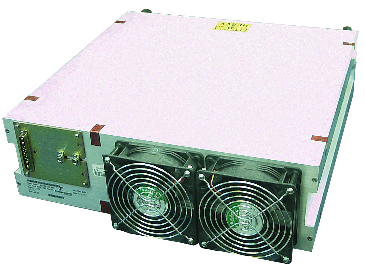
Click to zoom
Application Details
- Equipment Class
- AMP - Amplifier
- Date of Grant
- Mar 29, 2001
- Application Purpose
- Original Equipment
- Date of Application
- Mar 29, 2001
- Equipment Note
- Multi-Channel Cellular Amplidier
- Frequency Range
- 869.00000000 - 894.00000000
- Company
- Powerwave Technologies Inc
- Country
- United States
Documents & Files
Document Text
Text extracted from the exhibit documents filed with the FCC. Open a document above to read the original.
Users Manual
869-894 MHz 044-05095 Rev. AFebruary 2001 Installation & Service Manual G3S-800-140 Multi-Carrier Amplifier System 869 – 894 MHz G3S-800-140 Installation & Service Manual 044-05095 Rev. Aii February 2001 Powerwave Technologies, Inc.Tel: (714) 466-1000 1801 E. St. Andrew PlaceFax: (714) 466-5800 Santa Ana, CA 92705Web Site: www.powerwave.com © 2001 Powerwave Technologies Incorporated. All rights reserved. Powerwave Technologies, and the Powerwave logo are registered trademarks Powerwave Technologies, Inc. reserves the right to make changes to the documentation and equipment, including but not limited to component substitution and circuitry changes. Changes that impact this manual may subsequently be incorporated in a later revision of this manual. G3S-800-140 Installation & Service Manual 044-05095 Rev. AiFebruary 2001 Table Of Contents Par. Section 1 Page No.General DescriptionNo. 1-1Introduction ......................................................................................................................... 1-1 1-2General Description .........................................................................................................1-1 1-3Functional And Physical Specifications ....................................................................... 1-1 1-4Equipment Changes ...........................................................................................................1-1 1-5Ordering Information .........................................................................................................1-2 Section 2 Installation 2-1Introduction ......................................................................................................................... 2-1 2-2Electrical Service Recommendations ........................................................................... 2-1 2-3 Unpacking and Inspection ............................................................................................... 2-1 2-4Installation Instructions ...................................................................................................2-2 2-5Amplifier Module Connectors ......................................................................................... 2-2 2-5.1Amplifier Module Status, Alarm, Control, and Power Connector ............................ 2-3 2-5.2Amplifier Module RF Connector...................................................................................... 2-4 Section 3 Operating Instructions 3-1Introduction ......................................................................................................................... 3-1 3-2Location and Function of Amplifier Module Controls and Indicators ..................... 3-1 3-3Initial Start-Up and Operating Procedures ................................................................... 3-4 Section 4 Principles of Operation 4-1Introduction ......................................................................................................................... 4-1 4-2RF Input Signal.................................................................................................................... 4-1 4-3RF Output Load .................................................................................................................... 4-1 4-4G3S-800-140 Amplifier Module........................................................................................ 4-1 4-4.1Main Amplifier.................................................................................................................... 4-2 4-4.2Error Amplifier .................................................................................................................... 4-2 4-4.3Amplifier Monitoring......................................................................................................... 4-2 4-4.4Amplifier Module Cooling ................................................................................................ 4-3 4-4.5Power Distribution ............................................................................................................ 4-3 4-4.6 Intermodulation .................................................................................................................. 4-3 4-4.7Two Tone Intermodulation ............................................................................................... 4-3 4-4.8Multitone Intermodulation ............................................................................................... 4-3 4-4.9Alarms .................................................................................................................................. 4-3 G3S-800-140 Installation & Service Manual 044-05095 Rev. AiiFebruary 2001 Section 5 Maintenance 5-1Introduction ......................................................................................................................... 5-1 5-2Periodic Maintenance ...................................................................................................... 5-1 5-3Test Equipment Required For Test.................................................................................. 5-1 5-4Clean Air Inlets/Outlets ....................................................................................................5-2 5-5Performance Test............................................................................................................... 5-2 5-5.1Amplifier System Performance Test .............................................................................. 5-2 5-5.2Amplifier IMD Test..............................................................................................................5.3 5-5.3Gain Test .............................................................................................................................. 5-3 5-5.4Harmonic Test..................................................................................................................... 5-3 5-5.5Spurious Emissions Test .........................…
Text truncated - open the document above for the full version.
Block Diagram
Functional Block Diagram
Cover Letter(s)
TCB RF Exposure Review Procedure Statement FCC ID:E675JS0051 Transmitter Category Device Type Product Category Approval and Review Procedures Used Specific Procedures: I Amplifier Fixed Transmitters identified in Table 1 of §1.1307 Section A SP(9) Grant Condition : The output level from power amplifier is dependent upon the level of the input drive signal. The power output listed is the maximum , whether per channel or composite. Emissionslisted correspond to AMPS, CDMA, W-CDMA, TDMA and CDPD operation. The antenna(s) used for this transmitter must be fixed-mounted on outdoor permanent structures. RF exposure compliance is addressedat the time of licensing, as required by the responsible FCC Bureau(s), including antenna co-locationrequirements of §1.1307(b)(3). SP9 Grant conditions have been reviewed by TCB and has made the determination that device complied with RF Exposure review procedures. Reviewed by Mike KuoCompliance Certification ServicesMarch 30, 2001
Cover Letter(s)
From: Anne Liang Sent: Friday, March 30, 2001 12:32 PM To: Mike Kuo Subject: FW: Powerwave Technologies Inc., FCC ID:E675JS0051, AN01T1263 Hi, Mike, Confirmation by e-mail. Thanks, Anne -----Original Message----- From: Jeff Dale [mailto:[email protected]] Sent: Friday, March 30, 2001 11:59 AM To: Anne Liang Cc: [email protected] Subject: RE: Powerwave Technologies Inc., FCC ID:E675JS0051, AN01T1263 Hi Anne, The schematics are correct. Sorry for the confusion on the model numbers, our marketing department wants to sell this amplifier module to different customers. Our overall model number series for this is G3S-800. The last three digits are the power output, hence the -140. There is no difference physically or electrically. Cheers, Jeff Dale Reliability Engineering Powerwave Technologies 1801 E. St. Andrew Pl. Santa Ana, CA 92705 (714) 466-1476 Direct (714) 466-5807 FAX New address and phone numbers effective 3/19/2001 -----Original Message----- From: Anne Liang [SMTP:[email protected]] Sent: Friday, March 30, 2001 12:14 PM To: '[email protected]' Subject: Powerwave Technologies Inc., FCC ID:E675JS0051, AN01T1263 Dear Jeff, The information I received from you had been forwarded to our Certification division. One last thing, would you please confirm that the attached schematics is for G3S-800-140? Thanks, Anne -----Original Message----- From: Mike Kuo Sent: Friday, March 30, 2001 12:07 PM To: Anne Liang Subject: RE: Powerwave Technologies Inc., FCC ID:E675JS0051, AN01T1263 Please have Powerwave to confirm that the attached schematic diagram is for G3S-800-140. M.Kuo << File: schematics.pdf >> -----Original Message----- From: Anne Liang Sent: Friday, March 30, 2001 11:58 AM To: CERTADM; Steve Cheng; Claudia Perez Cc: Mike Kuo Subject: Powerwave Technologies Inc., FCC ID:E675JS0051, AN01T1263 Response to the following questions: Ques 1. FCC ID: uploaded Ques 2. Exernal photos: Uploaded Ques 3. Request for confidentiality letter uploaded Ques 4. The right user manual for G3S-800-140 was uploaded Ques 5 & 6. Please see the reply from Powerwave: As far as the power output goes, the amp is rated at 140W continuous output, but the maximum power output is 180W for AMPS (F1D) (F8W) & CDPD (FXW), 170W for CDMA (F9W) which also applies for W-CDMA, and 160W for TDMA (DXW). There is a difference in rated and maximum output power, Mike Kuo or Barbara can probably help you out. These are the levels which appear on the grant. 6. Theory of operation: Uploaded Best regards, Anne -----Original Message----- From: certadm [mailto:[email protected]] Sent: None To: [email protected]; [email protected] Cc: [email protected]; [email protected] Subject: Powerwave Technologies Inc., FCC ID:E675JS0051, AN01T1263 Notice_content ------------- Question #1: Please provide FCC ID label and proposed location. Question #2: Please provide External Photo of EUT. Question #3: As indicated fro m previous submission, the applicant would like to request for confiden tiality on information provided. Please confirm that there is no reque st for confidentiality for this submission. Question #4: The user ma nual provided is for model no:G3S-800-160. However, the model name ind icated on the test report is G3S-800-140. Please confirm the user manu al provided is applicable for G3S-800-140. Question #5: The G3S-800- 160 user manual indicates the device is 160W amplifier. However, this application is requesting for 180W amplifier. Please explain. Quest ion #6: The G3S-800-160 user manual indicates the device is designed to be used as AMPS/CDMA/TDMA/CDPD/W-CDMA. However, the application liste d emission designator as F1D, F8W, F9W and DXW. Please list the type o f modulations in associated with emission designator. Question #7: P lease provide theory of operation. Best Regards Mike Kuo / TCB Ce rtifier The items indicated above must be submitted before processing c an continue on the above referenced application. Failure to provide the requested information within 60 days of the original e-mail date may r esult in application dismissal and forfeiture of the filing fee. Also, please note that partial responses increase processing time and should not be submitted. Any questions about the content of this correspondenc e should be directed to the e-mail address listed below the name of the sender.
ID Label/Location Info
PROPOSED FCC ID LABEL AND LOCATION POWERWAVE TECHNOLOGIES, INC. FCC ID: E675JS0051 FCC ID LABEL LOCATION
Operational Description
G3S-800-140 Installation & Service Manual 044-05095 Rev. A4-1February 2001 Section 4 Principles of Operation 4-1 Introduction This section contains a functional description of the Multicarrier Cellular Amplifier. 4-2 RF Input Signal The maximum input power for all carrier frequencies should not exceed the limits specified in ta- ble 1-2. For proper amplifier loop balance, the out of band components of the input signals should not exceed -40 dBc. The input VSWR should be 2:1 maximum (or better). 4-3 RF Output Load The load impedance should be as good as possible (1.5:1 or better) in the working band for good power transfer to the load. If the amplifier is operated into a filter, it will maintain its distortion characteristics outside the signal band even if the VSWR is infinite, provided the reflected power does not exceed one watt. A parasitic signal of less than one watt incident on the output will not cause distortion at a higher level than the normal forward distortion (i.e. -60 dBc). 4-4 G3S-800-140 Amplifier Module The G3S-800-140 amplifier is a linear, feed-forward power amplifier that operates in the 25 MHz frequency band from 869 MHz to 894 MHz. The amplifier modules are designed for parallel op- eration to achieve high peak power output, and for redundancy in unmanned remote locations. The amplifier module, figure 4-1, has an average output of 140 watts power (1400 watts peak power) with intermodulation products suppressed to better than -60 dBc below carrier levels. The amplifier provides an amplified output signal with constant gain and phase by adding approxi- mately 30 dB of distortion cancellation on the output signal. Constant gain and phase is main- tained by continuously comparing active paths with passive references, and correcting for small variations through the RF feedback controls. All gain and phase variations, for example those due to temperature, are reduced to the passive reference variations. Each amplifier module has an alarm and display board that monitors the amplifier performance. If a failure or fault occurs in an amplifier module, it is displayed on the individual amplifier front panel. The amplifier module is comprised of: Pre-amplifiers Main amplifier Error amplifier Two feed-forward loops with phase-shift and gain controls DC/DC power regulator Alarm monitoring, control and display panel The main amplifier employs class AB amplification for maximum efficiency. The error amplifier and feed forward loops are employed to correct signal nonlinearities introduced by the class AB main amplifier. The error amplifier operates in class AB mode. The RF input signals are ampli- fied by a preamp and coupled to an attenuator and phase shifter in the first feed-forward loop. The main signal is phase shifted by 180 degrees and amplified in the premain amplifier. The out- put from the premain amplifier is fed to the class AB main amplifier. The output from the main amplifier is typically 220 watts. The signal is output to several couplers and a delay line. The signal output from the main amplifier is sampled using a coupler, and the sample signal is combined with the main input signal and input to the second feed-forward loop. The error signal is G3S-800-140 Installation & Service Manual 044-05095 Rev. A4-2February 2001 attenuated, phase shifted 180 degrees, then fed to the error amplifier where it is amplified to a level identical to the sampled output from the main amplifier. The output from the error amplifier is then coupled back and added to the output from the main amplifier. The control loops continu- ously make adjustments to cancel out any distortion in the final output signals. Pre Amp Pre Main Main Amp Error Amp Delay Feed Forward Loop control 2nd Loop Phase & Gain 1st Loop Phase & Gain Delay Alarms & Display +15 +5 -5 Power Supply -30dB -10dB RF Out RFL PWR FWD PWR Front Panel Smart Rack +27VDC Figure 4-1 G3S-800-140 Power Amplifier Module Functional Block Diagram The 2nd loop control section obtains a sample of the distortion added to the output signals by the main amplifiers, phase shifts the signals by 180 degrees, then feeds it to the error amplifier. There it is amplified to the same power level as the input sample and coupled on to the main out- put signal. The final output is monitored by the 2nd loop and adjusted to ensure that the signal distortion and IMD on the final output is canceled out. 4-4.1 Main Amplifier The input and output of the amplifier employ two-stage, class AB amplifiers which provide ap- proximately 32 dB of gain in the 25 MHz frequency band from 869 to 894 MHz. The amplifier op- erates on +27 Vdc, and a bias voltage of +5 Vdc, and is mounted directly on a heat sink which is temperature monitored by a thermostat. If the heat sink temperature exceeds 85 °C, the thermo- stat opens and a high temperature fault occurs. The alarm logic controls the +5 Vdc bias voltage which shuts down the amplifier. 4-4.2 Error Amplifier The main function of the error amplifier is to sample and amplify the signal distortion level gener- ated by the main amplifier, to a level that cancels out the distortion and IMD when the error signal is coupled onto the main signal at the amplifier output. The error amplifier is a balanced multi- stage, class AB amplifier, has 51 dB of gain, and produces up to an 80-watt output. The amplifier operates on 27 Vdc and a bias voltage of +5 Vdc, and is mounted directly on a heat sink. 4-4.3 Amplifier Monitoring In the main and error amplifier modules, all normal variations are automatically compensated for by the feedforward loop control. However, when large variations occur beyond the adjustment range of the loop control, a loop fault will occur. The alarms are displayed on the front panel indi- cators and output via a 21-pin connector on the rear of the module to the subrack summary board for subsequent remote monitoring via the ALARMS connector. Refer to paragraph 2-5 as well as figure 2-2 and table 2-2 for a descript…
Text truncated - open the document above for the full version.
Parts List/Tune Up Info
G3S-800-140 Installation & Service Manual 044-05095 Rev. A5-2February 2001 Table 5-2 Test Equipment Required NomenclatureManufacturerModel Signal GeneratorRDLIMD-801D-03A 30 dB Attenuator, 500 WattWeinschel Corp.53-30-34 20 dB Attenuator, 20 Watt (2 each) Tenuline Spectrum AnalyzerH.P.8560E Coax Directional CouplerH.P.778D Power Meter/SensorH.P.437B/8481A Network AnalyzerH.P.8753C Current Probe 5-4 Cleaning Air Inlets/Outlets The air inlets and outlets should be cleaned every 30 days. If the equipment is operated in a se- vere dust environment, they should be cleaned more often as necessary. Turn off DC power source before removing fans. If dust and dirt are allowed to accumulate, the cooling efficiency may be diminished. Using either compressed air or a brush with soft bristles, loosen and remove accumulated dust and dirt from the air inlet panels. 5-5 Performance Test Performance testing should be conducted every 12 months to ensure that the amplifier system meets the operational specifications listed in table 5-3. Also verify system performance after any amplifier module is replaced in the field. The test equipment required to perform the testing is listed in table 5-2, and the test setup is shown in figure 5-1. NOTE The frequencies used in this test are typical for an amplifier with a 25 MHz band from 869 MHz to 894 MHz. Select evenly spaced F1, F2, F3, and F4 frequencies that cover the instantaneous bandwidth of your system. 5-5.1 Amplifier System Performance Test This test is applicable to the G3S-800-140 amplifier modules. To perform the test, proceed as follows: 1. Connect test equipment to the amplifier as shown in figure 5-1. NOTE Do not apply any RF signals at this time. Turn on signal generator and set frequency F1 to 880 MHz, F2 to 883 MHz, F3 to 886 MHz, and F4 to 889 MHz. Adjust each signal generator output so that the sum power output from all four signal generators equals -6 dBm at the input. G3S-800-140 Installation & Service Manual 044-05095 Rev. A5-3February 2001 Figure 5-1 Amplifier System Test Setup Diagram 5-5.2 Amplifier IMD Test And Current Test 2. Adjust attenuator for an input signal at -10 dBm. Turn on the amplifier by setting RF ON switch of amplifier. Adjust variable attenuator to set amplifier power output on power meter to 140 watts. Measure IMD on spectrum analyzer. IMD should be -60 dBc max. Record test data in table 5-3. Set RF ON switch to OFF. 3. With the amplifier module set at 140 watts power output, use the current probe (magnetic field type) and measure the dc current flow from the +27 Vdc power source. Current should be 70 amps maximum. Record test data in table 5-3. 5-5.3 Gain Test 4. Disconnect spectrum analyzer from test setup, and connect the network analyzer. 5. Set network analyzer as follows: Ø Power output to -10 dBm. Ø Frequency start to 869 MHz. Ø Frequency stop to 894 MHz. Ø Normalize the network analyzer for gain and return loss. 6. Check the gain across the band from 869 MHz to 894 MHz. Gain should be between 58 dB. Record test data in table 5-3. 5-5.4 Harmonics Test 7. 10.With the power set at 140 watts power output, use the spectrum analyzer and check the frequency band from 869 MHz to 894 MHz for harmonics. Harmonics should be 5 dBm maximum. Record test data in table 5-3. Unit Under Test G3S-800-140 Plug-in Amplifier Module +27 Vdc GndRF In RF Out 20 dB Directionl Coupler 30 dB Attenuator 500 W 20 dB Attenuator 20 W Power Meter Sensor Head 8482A 20 dB Attenuator 20 W Directionl Coupler Power Meter Sensor Head 8482A Network Analyzer 8753C Signal Generator Filter / Isotlator 10 dB Variable Attenuator Spectrum Analyzer 8651E G3S-800-140 Installation & Service Manual 044-05095 Rev. A5-4February 2001 5-5.5 Spurious Test 8. With the power amplifier set at 140 watts power output, use the spectrum analyzer and check the frequency band from 869 MHz to 894 MHz for spurious signals. Spurious signals should be -60 dBc maximum. Record test data in table 5-3. 5-5.6 Input Return Loss Test 9. Reset and turn on amplifier module. Read and record the S 11 return loss measurement on network analyzer. Input return loss should be –16 dB maximum. Record test data in table 5-3. G3S-800-140 Installation & Service Manual 044-05095 Rev. A5-5February 2001 Table 5-3 Multicarrier Cellular Amplifier Test Data Sheet DATE _________________________________ AMPLIFIER S/N _________________________ TEST CONDITIONS: Load and Source Impedance: 50 Ohms VSWR: < 1.2:1 Supply Voltage: +27 Vdc ±1.0 Vdc TESTSPECIFICATIONMIN MAXDAT A 4-TONE IMD Vcc = 27 Vdc PO = 140 W Freq.: 880, 883, 886, and 889 MHz -60 dBc RF Gain Vcc = 27 Vdc PO = 140 W Freq. = 880 MHz 57.5 dB58.5 dB Gain Flatness Vcc = 27 Vdc ±1 Vdc PO =140 W 869-894 MHz Band -0.5 dB+0.5 dB Harmonics Vcc = 27 Vdc PO = 140 W 869-894 MHz Band 5 dBm Spurious Vcc = 27 Vdc PO =140 W 869-894 MHz Band -60 dBc Input Return Loss Vcc = 27 Vdc PO = 140 W 869-894 MHz Band -16 dB DC Power Vcc = 27 Vdc PO = 140 W 4 Tones 70 Amps PASS _________________________________FAIL _______________________________ Tested by ______________________________
Test Report
FCC CFR47 PART 22 CERTIFICATION TEST REPORT FOR 869-894MHz RACK MOUNTABLE MULTI-CHANNEL AMPLIFIER MODEL: G3S-800-140-030 FCC ID: E675JS0051 REPORT NUMBER: 01U0659-1 ISSUE DATE: MARCH 16, 2001 Prepared for POWERWAVE TECHNOLOGIES, INC. 2026 McGAW AVENUE IRVINE, CA 92614 USA Prepared by COMPLIANCE CERTIFICATION SERVICES, INC. 561 F MONTEREY ROAD MORGAN HILL, CA 95037 USA TEL: 408-463-0885 FAX: 408-463-0888 REPORT NO: 01U0659-1 DATE: MARCH 16, 2001 FCC ID: E675JS0051 EUT: 869-894MHz RACK MOUNTABLE MULTI-CHANNEL AMPLIFIER PAGE 0 OF 67 COMPLIANCE CERTIFICATION SERVICES DOCUMENT NO:CCSUP4031A 561 F MONTEREY ROAD, MORGAN HILL, CA 95037 USA TEL:(408) 463-0885 FAX:(408) 463-0888 This report shall not be reproduced except in full, without the written approval of CCS. This document may be altered or revised by Compliance Certification Services personnel only, and shall be noted in the revision section of the document. TABLE OF CONTENTS PAGE 1. FCC CERTIFICATION INFORMATION.................................................................................................................1 2. TEST FACILITY................................................................................................................................................................2 3. ACCREDITATION AND LISTING.............................................................................................................................2 4. MEASUREMENT INSTRUMENTATION.................................................................................................................2 5. MEASURING INSTRUMENT CALIBRATION......................................................................................................2 6. UNITS OF MEASUREMENT........................................................................................................................................3 7. EQUIPMENT MODIFICATIONS................................................................................................................................3 8. TEST EQUIPMENT LIST................................................................................................................................................4 9. EUT SETUP PHOTOS......................................................................................................................................................5 10. EXTERNAL I/O CABLE CONSTRUCTION DESCRIPTION.......................................................................9 11. CONFIGURATION BLOCK DIAGRAM.............................................................................................................9 12. PART 2: CERTIFICATIO N TEST REQUIREMENT:...................................................................................10 SECTION 2.1046: RF POWER OUTPUT..........................................................................................................................10 SECTION 2.1047: MODULATION CHARACTERISTICS...........................................................................................11 SECTION 2.1049: OCCUPIED BANDWIDTH................................................................................................................11 SECTION 2.1051: SPURIOUS EMISSION AT ANTENNA TERMINALS...............................................................23 SUBSTITUTION METHOD: (RADIATED EMISSIONS).....................................................................................................64 SECTION 2.1055: FREQUENCY STABILITY................................................................................................................67 REPORT NO: 01U0659-1 DATE: MARCH 16, 2001 FCC ID: E675JS0051 EUT: 869-894MHz RACK MOUNTABLE MULTI-CHANNEL AMPLIFIER PAGE 1 OF 67 COMPLIANCE CERTIFICATION SERVICES DOCUMENT NO:CCSUP4031A 561 F MONTEREY ROAD, MORGAN HILL, CA 95037 USA TEL:(408) 463-0885 FAX:(408) 463-0888 This report shall not be reproduced except in full, without the written approval of CCS. This document may be altered or revised by Compliance Certification Services personnel only, and shall be noted in the revision section of the document. 1. FCC CERTIFICATION INFORMATION The following information is in accordance with FCC Rules, 47CFR Part2, Subpart J, Sections 2.1033 – 2.1055. 2.1033(c)(1) Applicant: POWERWAVE TECHNOLOGIES, INC. 2026 McGAW AVENUE IRVINE, CA 92614 Contact person: Jeff Dale Telephone number: (949) 809-1466 2.1033(c)(2) FCC ID: E675JS0051 2.1033(c)(6) Range of Operation Power 180 Watts 2.1033(c)(7) Maximum Power Rating 180 Watts Section 22.913(a); Maximum ERP. The effective radiated power (ERP) of base transmitters and cellular repeaters must not exceed 500 Watts. TYPE OF EQUIPMENT: Cellular Amplifier MEASUREMENT DISTANCE: 3 METER TECHNICAL LIMIT: FCC 22.359, 22.917 FCC RULES: PART 22 EQUIPMENT AUTHORIZATION PROCEDURE CERTIFICATION / PERMISSIVE CHANGE MODIFICATIONS MADE ON EUT YES (REFER TO PAGE 7) NO The above equipment was tested by Compliance Certification Services for compliance with the requirements set forth in the FCC CFR 47, PART 22. The results of testing in this report apply to the product/system, which was tested only. Other similar equipment will not necessarily produce the same results due to production tolerance and measurement uncertainties. Tested and/or Reviewed By: RELEASED FOR CCS BY: PETE KREBILL TOM COKENIAS ASSOCIATE EMC ENGINEER DIRECTOR OF ENGINEERING COMPLIANCE CERTIFICATION SERVICES COMPLIANCE CERTIFICATION SERVICES REPORT NO: 01U0659-1 DATE: MARCH 16, 2001 FCC ID: E675JS0051 EUT: 869-894MHz RACK MOUNTABLE MULTI-CHANNEL AMPLIFIER PAGE 2 OF 67 COMPLIANCE CERTIFICATION SERVICES DOCUMENT NO:CCSUP4031A 561 F MONTEREY ROAD, MORGAN HILL, CA 95037 USA TEL:(408) 463-0885 FAX:(408) 463-0888 This report shall not be reproduced except in full, without the written approval of CCS. This document may be altered or revised by Compliance Certification Services personnel only, and shall be noted in the revision section of the document. 2. TEST FACILITY Th…
Text truncated - open the document above for the full version.
Test Report
REPORT NO: 01U0659-1 DATE: MARCH 16, 2001 FCC ID: E675JS0051 EUT: 869-894MHz RACK MOUNTABLE MULTI-CHANNEL AMPLIFIER PAGE 11 of 67 COMPLIANCE CERTIFICATION SERVICES DOCUMENT NO:CCSUP4031A 561 F MONTEREY ROAD, MORGAN HILL, CA 95037 USA TEL:(408) 463-0885 FAX:(408) 463-0888 This report shall not be reproduced except in full, without the written approval of CCS. This document may be altered or revised by Compliance Certification Services personnel only, and shall be noted in the revision section of the document. SECTION 2.1047: MODULATION CHARACTERISTICS Not applicable. EUT is a power amplifier. SECTION 2.1049: OCCUPIED BANDWIDTH TEST SETUP FOR OUTPUT: Minimum Requirement: Section 2.1049(i); Transmitters designed for other types of modulation-when modulated by an appropriate signal of sufficient amplitude to be representative of the type of service in which used. A description of the input signal should be supplied. SIGNAL GENERATOR COMBINER PRE-AMP EUT ATTENUATOR DIRECTIONAL COUPLER SPECTRUM ANALYZER POWER METER SPECTRUM ANALYZER SIGNAL GENERATOR REPORT NO: 01U0659-1 DATE: MARCH 16, 2001 FCC ID: E675JS0051 EUT: 869-894MHz RACK MOUNTABLE MULTI-CHANNEL AMPLIFIER PAGE 12 of 67 COMPLIANCE CERTIFICATION SERVICES DOCUMENT NO:CCSUP4031A 561 F MONTEREY ROAD, MORGAN HILL, CA 95037 USA TEL:(408) 463-0885 FAX:(408) 463-0888 This report shall not be reproduced except in full, without the written approval of CCS. This document may be altered or revised by Compliance Certification Se…
Text truncated - open the document above for the full version.
Contact Information
Applicant
Jeff Dale(Principal Reliability Engineer)
Technical Contact
Compliance Certification ServicesTom Cokenias
[email protected]408-463-0885
561F Monterey Road · Morgan Hill, California · United States
Test Firm
Compliance Certification Services IncSteve Cheng
Technical Specifications
| # | Rule Parts | Frequency Range | Power Output | Emission | Tolerance |
|---|---|---|---|---|---|
| 5 | 22.901(d) | 869 MHz - 894 MHz | 160 W | DXW | Amp |
Other Applications from Powerwave Technologies Inc

E675JS0123
Nov 03, 2011Multi-carrier RF Power Amplifier
Equipment Class
AMP - Amplifier
E675JS0120
Aug 26, 2010Nexus Dual Band Repeater
Equipment Class
TNB - Licensed Non-Broadcast Station Transmitter
E675JS0119
Aug 01, 2010Nexus Dual Band Repeater
Equipment Class
PCB - PCS Licensed Transmitter
E675JS0118
Jul 26, 2010Nexus Dual Band Repeater
Equipment Class
PCB - PCS Licensed Transmitter
E675JS0096
Jan 10, 2008Wideband Radio Head
Equipment Class
TNB - Licensed Non-Broadcast Station Transmitter