E675JS0062GSM/EDGE Booster Amplifier, SPA9329-35
Powerwave Technologies Inc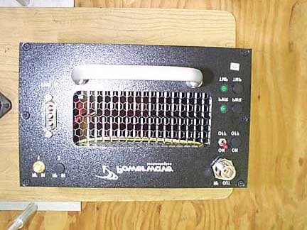
Click to zoom
Application Details
- Equipment Class
- AMP - Amplifier
- Date of Grant
- Nov 17, 2002
- Application Purpose
- Original Equipment
- Date of Application
- Nov 17, 2002
- Equipment Note
- GSM/EDGE Booster Amplifier, SPA9329-35
- Frequency Range
- 1930.00000000 - 1990.00000000
- Company
- Powerwave Technologies Inc
- Country
- United States
Documents & Files
Document Text
Text extracted from the exhibit documents filed with the FCC. Open a document above to read the original.
Users Manual
1930-1990 MHz Installation and Service Manual Model SPA9329-35 Booster Power Amplifier Copyright Powerwave Technologies, Inc., October 2002. All rights reserved October 2002 SPA9329-35 Installation & Service Manual October 2002 © 2002 Powerwave Technologies Incorporated. All rights reserved. Powerwave Technologies, and the Powerwave logo are registered trademarks Powerwave Technologies, Inc. reserves the right to make changes to the documentation and equipment, including but not limited to component substitution and circuitry changes. Changes that impact this manual may subsequently be incorporated in a later revision of this manual. Powerwave Technologies, Inc. Tel: (714) 466-1000 1801 East St. Andrew Place (888) 797-9283 Santa Ana, CA 92705 Fax: (714) 466-5800 Web Site: www.powerwave.com Copyright Powerwave Technologies, Inc., October 2002. All rights reserved ii October 2002 SPA9329-35 Installation & Service Manual Table Of Contents Par. Section 1 Page No. General Description No. 1-1 Introduction.....................................................................................................................................................1-1 1-2 General Description.......................................................................................................................................1-1 1-3 Functional and Physical Specifications....................................................................................................1-1 1-4 Ordering Information.....................................................................................................................................1-1 Section 2 Installation 2-1 Introduction.....................................................................................................................................................2-1 2-2 Electrical Service Recommendations........................................................................................................2-1 2-3 Unpacking and Inspection............................................................................................................................2-1 2-4 Installation Instructions................................................................................................................................2-2 2-5 +27 VDC Power & Ground Connector.........................................................................................................2-2 Section 3 Operating Instructions 3-1 Introduction.....................................................................................................................................................3-1 3-2 Initial Start-Up and Operating Procedures...............................................................................................3-1 Section 4 Principles of Operation 4-1 Introduction.....................................................................................................................................................4-1 4-2 RF Input Signal................................................................................................................................................4-1 4-3 RF Output Load................................................................................................................................................4-1 4-4 Amplifier Functional Description................................................................................................................4-1 4-5 Amplifier Module Cooling............................................................................................................................4-1 4-6 Power Distribution.........................................................................................................................................4-2 Section 5 Maintenance 5-1 Introduction.....................................................................................................................................................5-1 5-2 Periodic Maintenance...................................................................................................................................5-1 5-3 Module Field Replacement..........................................................................................................................5-1 Section 6 Troubleshooting 6-1 Introduction.....................................................................................................................................................6-1 6-2 Trouble shooting.............................................................................................................................................6-1 6-3 Return for Service Procedures....................................................................................................................6-1 6-3.1 Obtaining an RMA..........................................................................................................................................6-1 6-3.2 Repackaging for Shipment...........................................................................................................................6-1 Copyright Powerwave Technologies, Inc., October 2002. All rights reserved October 2002 iii SPA9329-35 Installation & Service Manual List Of Illustrations Figure Page No. No. 1-1 SPA9329-35 Front Isometric View ......................................................................................................... 1-3 1-2 SPA9329-35 Rear Isometric View .......................................................................................................... 1-3 1-3 SPA9329-35 Front View............................................................................................................................ 1-4 1-4 SPA9329-35 Rear View ............................................................................................................................ 1-4 1-5 SPA9329-35 Side View.....................................................................…
Text truncated - open the document above for the full version.
External Photos
Top Bottom Left Right Front Back
ID Label/Location Info
SPA9329-35 SPA9329-35 Label Location - Rear Isometric View Copyright Powerwave Technologies, Inc., October 2002. All rights reserved 1-3 October 2002
Internal Photos
Top Exposed RF Section Top Exposed 500-02215 PCB Top 500-02215 PCB Bottom 500-02214 PCB top 500-02214 PCB Bottom 500-01405 PCB Top 500-01405 PCB Top Section 1 500-01405 PCB Top Section 2 500-01405 PCB Top Section 3 500-01405 PCB Top Section 4 500-01405 PCB Bottom 500-01405 RF Module 1 500-01405 RF Module 2 500-01405 RF Module 3 500-01405 RF Module 4 500-01405 RF Module 5 500-02215 RF Module 500-02230 PCB Top 500-02230 PCB Top 2 500-02230 PCB Section 1 500-02230 PCB Section 2 500-02230 PCB Section 3 500-02230 PCB Back RF Input Port RF Input Cable RF Output Cable RF Input of RF Enclosure RF Power Module Front RF Power Module Side Indent for RF Power Module RF Enclosure Top RF Enclosure Front RF Enclosure Bottom Backside of RF Front Panel Heat Sink Bottom Heat Sink Top
Operational Description
SPA9329-35 Installation & Service Manual Section 4 Principles of Operation 4-1 Introduction This section contains a functional description of the SPA9329-35 power booster amplifier. 4-2 RF Input Signal The maximum input power should not exceed the limits specified in table 1-1. 4-3 RF Output Load The load impedance should be as good as possible (1.5:1 or better) in the working band for good power transfer to the load. 4-4 Amplifier Functional Description The SPA9329-35 power booster amplifier, shown in figure 4-1, operates in the 1930 MHz to 1990 MHz range. The operating band is determined by the operating frequency selection(s) of the base station (refer to table 1-2). The amplifier module consists of a single carrier amplifier pal- let with the necessary combining and filtering to produce up to 100 watts (50 dBm) of output power with a maximum gain of 23 dB. The amplifier employs a class AB amplifier for maximum efficiency. The amplifier operates on +27 Vdc. The amplifier is compliant to the requirements of FCC Part 24 with respect to spurious emissions (see table 1-2). All gain variations, for example those due to temperature, are reduced to the pas- sive reference variations. RF In RF Out Reverse Detector Comparator and Alarm Circuit SPA9329-35 +27 VDC TMP Pre-Amp Main Amplifier Figure 4-1 SPA9329-35 Booster Amplifier Block Diagram 4-5 Amplifier Module Cooling Each amplifier module is cooled using a rear-mounted fan circulating air flow across the amplifier heat sinks, the air then exits out the front of the module. This provides sufficient cooling to main- tain the amplifier within the specified operating temperature range. Copyright Powerwave Technologies, Inc., October 2002. All rights reserved 4-1 October 2002 SPA9329-35 Installation & Service Manual 4-6 Power Distribution Primary DC power for the amplifier is provided by the host system. The amplifier generates all the required voltages internally from the main source. Copyright Powerwave Technologies, Inc., October 2002. All rights reserved 4-2 October 2002
Parts List/Tune Up Info
SPA9329-35 Installation & Service Manual Section 5 Maintenance 5-1 Introduction This section contains periodic maintenance and performance test procedures for the SPA9329- 35 power booster amplifier. It also contains a list of test equipment required to perform the identified tasks. NOTE Check your sales order and equipment warranty before attempting to service or re- pair the unit. Do not break the seals on equipment under warranty or the warranty will be null and void. Do not return equipment for warranty or repair service until proper shipping instructions are received from the factory. 5-2 Periodic Maintenance Periodic maintenance requirements are listed in table 5-1. Table 5-1 also lists the intervals at which the tasks should be performed. Table 5-1 Periodic Maintenance Task Interval Action Inspection Cables & Connectors 12 Months Inspect signal and power cables for frayed insulation. Check RF connectors to be sure that they are tight. Performance Tests No periodic maintenance is necessary beyond that recommended by the base station manufacturer. 5-3 Module Field Replacement The SPA9329-35 power booster amplifier module can be replaced in the field on site by a qualified technician with adequate ESD protection and experience maintaining RF power amplifi- ers and similar equipment. To replace a power amplifier module, proceed as follows: 1. Set the amplifier module DC power ON–OFF switch to OFF. 2. Disconnect the DC power cable from the amplifier module. 3. Disconnect the RF IN cable. 4. Disconnect the RF OUT cable. 5. Carefully remove the amplifier module. 6. Install replacement in reverse order. Copyright Powerwave Technologies, Inc., October 2002. All rights reserved 5-1 October 2002 SPA9329-35 Installation & Service Manual Section 6 Troubleshooting 6-1 Introduction This section contains a list of problems and a few suggested actions that may correct any prob- lem with the SPA9329-35 power booster amplifier. If the suggested corrective action does not eliminate the problem, please contact your Powerwave field representative or the factory for fur- ther instructions. NOTE Check your sales order and equipment warranty before attempting to service or re- pair the unit. Do not break the seals on equipment under warranty or the warranty will be null and void. Do not return equipment for warranty or repair service until proper shipping instructions are received from the factory. 6-2 Troubleshooting Refer to table 6-1 for troubleshooting suggestions. Table 6-1 Troubleshooting Symptom Suggested Action Amplifier Module Inoperative Check for proper power supply voltage and that power input connector is properly seated in mating connector. Amplifier Module Not Enabled Check that the module ON–OFF power switch is set to the ON position. TMP Indicator Not Illuminated Verify input RF is within specified power and frequency limits. Check that the cooling fan is operating. 6-3 Return For Service Procedures When returning products to Powerwave, the following procedures will ensure optimum response. 6-3.1 Obtaining An RMA A Return Material Authorization (RMA) number must be obtained prior to returning equipment to the factory for service. Please contact our Repair Department at (888) 797-9283 or (714) 466- 1000 to obtain this number, or FAX your request to (714) 466-5816. Failure to obtain this RMA number may result in delays in receiving repair service. 6-3.2 Repackaging For Shipment To ensure safe shipment of the amplifier, it is recommended that the package designed for the amplifier be used. The original packaging material is reusable. If it is not available, contact Powerwave’s Customer Service Department for packing materials and information. Copyright Powerwave Technologies, Inc., October 2002. All rights reserved 6-1 October 2002
Test Report
Page 1 of 43 Report No.: FC02-100 POWERWAVE TECHNOLOGIES TEST REPORT FOR THE GSM/EDGE BOOSTER AMPLIFIER, SPA9329-35 FCC PART 24 AND PART 15 SUBPART B SECTION 15.107 CLASS A COMPLIANCE DATE OF ISSUE: NOVEMBER 8, 2002 PREPARED FOR: Powerwave Technologies 1801 E. St. Andrew Place Santa Ana, CA 92705 PREPARED BY: Mary Ellen Clayton CKC Laboratories, Inc. 5473A Clouds Rest Mariposa, CA 95338 P.O. No.: 60772 W.O. No.: 79687 Date of test: October 22-28, 2002 Report No.: FC02-100 This report contains a total of 43 pages and may be reproduced in full only. Partial reproduction may only be done with the written consent of CKC Laboratories, Inc. The results in this report apply only to the items tested, as identified herein. Page 2 of 43 Report No.: FC02-100 TABLE OF CONTENTS Administrative Information............................................................................................. 3 Summary of Results ........................................................................................................ 4 Conditions for Compliance ............................................................................................. 4 Approvals ........................................................................................................................ 4 Equipment Under Test (EUT) Description ..................................................................... 5 Equipment Under Test .................................................................................................... 5 Peripheral Devices........................................................................................................... 5 Temperature and Humidity During Testing .................................................................... 6 2.1033(c)(3) Userís Manual ............................................................................................ 6 2.1033(c)(4) Type of Emissions...................................................................................... 6 2.1033(c)(5) Frequency Range........................................................................................ 6 2.1033(c)(6) Operating Power......................................................................................... 6 2.1033(c)(7) Maximum Power Rating ............................................................................ 6 2.1033(c)(8) DC Voltages ............................................................................................... 6 2.1033(c)(9) Tune-Up Procedure .................................................................................... 6 2.1033(c)(10) Schematics and Circuitry Description...................................................... 6 2.1033(c)(11) Label and Placement ................................................................................ 6 2.1033(c)(12) Submittal Photos ...................................................................................... 6 2.1033(c)(13) Modulation Information ........................................................................... 6 2.1033(c)(14)/2.1046/24.232(a) - RF Power Output....................................................... 7 2.1033(c)(14)/2.1047(b) - Audio Frequency Response .................................................. 11 2.1033(c)(14)/2.1047(b) - Modulation Limiting Response............................................. 11 2.1033(c)(14)/2.1049(i) - Occupied Bandwidth.............................................................. 11 2.1033(c)(14)/2.1051/24.238(a) - Spurious Emissions at Antenna Terminal ................. 25 2.1033(c)(14)/2.1053/24.238(a) - Field Strength of Spurious Radiation ........................ 33 2.1033(c)(14)/2.1055 - Frequency Stability.................................................................... 37 2.1091 ñ MPE Calculations............................................................................................. 37 15.107 ñ AC Conducted Emissions ................................................................................ 38 Page 3 of 43 Report No.: FC02-100 ADMINISTRATIVE INFORMATION DATE OF TEST: October 22-28, 2002 DATE OF RECEIPT: October 22, 2002 PURPOSE OF TEST: To demonstrate the compliance of the GSM/EDGE Booster Amplifier, SPA9329-35 with the requirements for FCC Part 24 and Part 15 Subpart B Section 15.107 Class A devices. TEST METHOD: ANSI C63.4 (1992) and FCC Part 24 FREQUENCY RANGE TESTED: 150 kHz - 20 GHz MANUFACTURER: Powerwave Technologies 1801 E. St. Andrew Place Santa Ana, CA 92705 REPRESENTATIVE: Jeffrey Dale TEST LOCATION: CKC Laboratories, Inc. 110 Olinda Place Brea, CA 92621 Page 4 of 43 Report No.: FC02-100 SUMMARY OF RESULTS As received, the Powerwave Technologies GSM/EDGE Booster Amplifier, SPA9329-35 was found to be fully compliant with the following standards and specifications: United States Ø FCC Part 24 and method Ø FCC Part 15 Subpart B Section 15.107 Class A using: Ø ANSI C63.4 (1992) method CONDITIONS FOR COMPLIANCE No modifications to the EUT were necessary to comply. Conducted emissions performed at 230V because that is the only voltage at which the EUT operates. APPROVALS QUALITY ASSURANCE:TEST PERSONNEL: Steve Behm, Director of Engineering ServicesEddie Wong, EMC Engineer Joyce Walker, Quality Assurance Administrative Manager Septimiu Apahidean, EMC/Lab Manager Page 5 of 43 Report No.: FC02-100 EQUIPMENT UNDER TEST (EUT) DESCRIPTION The 100 W Booster amplifier, 1930-1990 MHz.tested by CKC Laboratories was a production unit. The SPA9329-35 is a linear booster amplifier that operates in a fequency range from 1930 MHz to 1990 MHz and provides 100 watts (50 dBm) of output power with a maximum gain of 23 dB. The amplifier is modular in design, and is ideally suited for use in GSM and EDGE base stations. EQUIPMENT UNDER TEST GSM/ EDGE Booster Amplifier Manuf: Powerwave Technologies Model: SPA 9329-35 Serial: 07 FCC ID: E67 pending PERIPHERAL DEVICES The EUT was tested with the following peripheral device(s): Power Supply Manuf: HP Model: 6269B…
Text truncated - open the document above for the full version.
Test Setup Photos
RF POWER AND OCCUPIED BANDWIDTH RF POWER AND OCCUPIED BANDWIDTH RF POWER AND OCCUPIED BANDWIDTH Direct Connect Direct Connect OATS OATS PHOTOGRAPH SHOWING MAINS CONDUCTED EMISSIONS PHOTOGRAPH SHOWING MAINS CONDUCTED EMISSIONS
Contact Information
Applicant
Jeff Dale(Principal Reliability Engineer)
Technical Contact
CKC LaboratoriesMary Ellen Clayton
[email protected]209-966-5240
5473-A Clouds Rest · Mariposa, California · United States
Non-Technical Contact
CKC LaboratoriesMary Ellen Clayton
[email protected]209-966-5240
Test Firm
CKC Laboratories, Inc.Steve Behm
Technical Specifications
| # | Rule Parts | Frequency Range | Power Output | Emission | Tolerance |
|---|---|---|---|---|---|
| 2 | 24 | 1.93 GHz - 1.99 GHz | 100 W | G7W | Amp |
Other Applications from Powerwave Technologies Inc

E675JS0123
Nov 03, 2011Multi-carrier RF Power Amplifier
Equipment Class
AMP - Amplifier
E675JS0120
Aug 26, 2010Nexus Dual Band Repeater
Equipment Class
TNB - Licensed Non-Broadcast Station Transmitter
E675JS0119
Aug 01, 2010Nexus Dual Band Repeater
Equipment Class
PCB - PCS Licensed Transmitter
E675JS0118
Jul 26, 2010Nexus Dual Band Repeater
Equipment Class
PCB - PCS Licensed Transmitter
E675JS0096
Jan 10, 2008Wideband Radio Head
Equipment Class
TNB - Licensed Non-Broadcast Station Transmitter