E675JS0066Power Amplifier
Powerwave Technologies Inc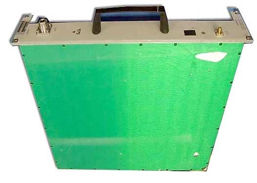
Click to zoom
Application Details
- Equipment Class
- AMP - Amplifier
- Date of Grant
- May 04, 2003
- Application Purpose
- Original Equipment
- Date of Application
- May 04, 2003
- Equipment Note
- Power Amplifier
- Frequency Range
- 1932.70000000 - 1987.30000000
- Company
- Powerwave Technologies Inc
- Country
- United States
Documents & Files
Document Text
Text extracted from the exhibit documents filed with the FCC. Open a document above to read the original.
Users Manual
2110-2170 MHz Operation Manual G3L-2100-30-B (DC) / G3L-2100-30-C (AC) Wideband Multi-Carrier Power Amplifier Operation Manual 2110 MHz – 2170 MHz 044-05133 Rev. A March 2003 G3L-2100-30-B/G3L-2100-30-C Operation Manual © 2003 Powerwave Technologies Incorporated. All rights reserved. Powerwave Technologies, and the Powerwave logo are registered trademarks Powerwave Technologies, Inc. reserves the right to make changes to the documentation and equipment, including but not limited to component substitution and circuitry changes. Changes that impact this manual may subsequently be incorporated in a later revision of this manual. March 2003 Powerwave Technologies, Inc. Tel: (714) 466-1000 1801 E. St. Andrew Place (888) 797-9283 Santa Ana, CA 92705 Fax: (714) 466-5800 Web Site: www.powerwave.com Copyright Powerwave Technologies, Inc., March 2003. All rights reserved 044-05133 Rev. A ii March 2003 G3L-2100-30-B/G3L-2100-30-C Operation Manual Section 1 General Description 1-1 Introduction This manual contains information and procedures for the operation of the model G3L-2100-30-B and G3L-2100-30-C Wideband (WCDMA) Multi-Carrier Power Amplifier (MCPA). The manual is organized into the following sections and appendix. Section 1 General Descri ption Section 2 O peration Appendix A Specifications 1-2 General Description The amplifiers are wideband, linear, feed-forward power amplifiers (WPAs) that operate in the 60 MHz frequency bandwidth from 2110 to 2170 MHz with an instantaneous bandwidth of 20 MHz. The amplifier provides linear amplification for single or multi-carrier WCDMA signals. The amplifi- ers communicate with the base station via a TLCI control interface bus; passing alarm and meas- urement information to the base station and receiving control information from the base station. 1-3 Hardware Interface There are three groups of interface connections located on the amplifier chassis. These are RF, power, and control interface (TLCI bus) as described in the paragraphs that follow. 1-3.1 RF The RF interface is located on the power amplifier front panel consists of the RF-In (TX-In) and RF-Out (TX-Out) connectors as shown in Figure 1-1. 1-3.2 Power Supply Power supply voltages (-48 VDC or 230 VAC) from the base station subrack are connected to the amplifier via connector X3, pins A – D located on the power amplifier rear panel as shown in fig- ure 1-1. Table 1-1 lists the voltages and descriptions for each pin. Table 1-1 Primary Power Connections Signal Group X3 Connector Pin Signal Name Description D -48VDC DC Minus (isolated from amplifier chassis) DC E +48VDC DC Plus (isolated from amplifier chas- sis) A L AC Phase (isolated from amplifier chassis) B N AC Zero (isolated from amplifier chas- sis) AC C PE AC Protective Ground (connected to chassis) Copyright Powerwave Technologies, Inc., March 2003. All rights reserved 044-05133 Rev. A 1-1 March 2003 G3L-2100-30-B/G3L-2100-30-C Operation Manual 1-3.3 TLCI Bus Communications The purpose of the TCLI bus is to provide a communications interface between the power ampli- fier and base station. The bus is connected from the base station subrack to the X3 connector located on the power amplifier rear panel as shown in figure 1-1. Table 1-2 lists the signal names and descriptions for each pin of the 24-pin connector. Table 1-2 TLCI Bus Connections Signal Group X3 Connector Pin Signal Name Description 2 AXMTP 3 AXMTN 18 ARCVP TLCI 19 ARCVN Ethernet, 10BASE-T 5 WPA_ID_BIT0 Hard-coded WPA ID 13 WPA_ID_BIT1 BIT0=LSB, BIT!=MSB WPA ID 21 WPA_ID_BIT2 OPEN=1=Logical High Gnd=0=Logical Low 1 4 8 9 10 11 12 17 20 GND 24 Ground Connected to WPA chassis ground Free 6, 7, 14. 15, 16, 22, 23 Reserved for WPA manufacture Copyright Powerwave Technologies, Inc., March 2003. All rights reserved 044-05133 Rev. A 1-2 March 2003 G3L-2100-30-B/G3L-2100-30-C Operation Manual 1-4 Alarms The WPA generates the following alarms and communicates then to the base station via the TLIC bus: • VSWR • Gain • Temperature • Over-Drive • Power Supply • Linearization The base station is able to query the current alarm status from the WPA. Fault status is cleared at unit reset which means that any alarm detected after reset is reported to the base station. The alarm status always represents existing conditions. 1-4.1 VSWR The WPA supervises the output (load) VSWR and gives the alarm based on the following limits as listed in table 1-3. Table 1-3 VSWR Alarm Limits VSWR Alarm Status Limits VSWR alarm ON VSWR at the output>8.5:1 @ phase 0-360º VSWR alarm OFF VSWR at the output<3.0:1 or when the VSWR alarm is dis- abled @ phase 0-360º 1-4.2 Gain The WPA supervises the gain of the unit and gives the gain alarm according to the limits listed in table 1-4. Table 1-4 Gain Alarm Limits Gain Alarm Status Limits Gain alarm ON Gain deviates more than ±1.5 dB from specified nominal gain or if the carrier cancellation loop is out of lock, the gain alarm is activated Gain alarm OFF Gain is within the specified range or disabled 1-4.3 Temperature The WPA monitors the internal temperature. The measured temperature must represent the base plate temperature of the main power amplifier. The alarm is given according to the limits listed in table 1-5. Copyright Powerwave Technologies, Inc., March 2003. All rights reserved 044-05133 Rev. A 1-3 March 2003 G3L-2100-30-B/G3L-2100-30-C Operation Manual Table 1-5 Temperature Alarm Limits Temperature Alarm Status Limits Temperature alarm ON Internal base plate temperature is equal or higher than 92ºC Temperature alarm OFF Internal base plate temperature decreases more than 10ºC from the alarm on temperature 1-4.4 Overdrive The overdrive alarm causes an automatic WPA shutdown. 1-4.5 Power Supply The WPA monitors the internal DC supply voltages and gives the power supply alarm if any of the voltages are out of the specified range. This alarm causes an automatic WPA shutdown. 1-4.6 Linearization In case of poor output signal, the linearization causes an automa…
Text truncated - open the document above for the full version.
Users Manual
G3L-1900-54/G3L-1900-54-A Installation & Service Manual Copyright Powerwave Technologies, Inc., April 2003. All rights reserved All specifications are subject to change without notice. Contact the factory for complete performance data. 044-05135 Rev. A A-1 April 2003 Appendix A. Specifications Table A-1 G3L-1900-54/54-A Wideband Multicarrier Cellular Amplifier Functional Specifications Frequency Range 1930 - 1990 MHz (60 MHz Bandwidth) Instantaneous Bandwidth 20 MHz * Total Typical / Maximum Input Power -15.7 - +4.8 / +5.8 dBm Total Output Power 54 W (47.3 dBm) Adjacent Channel Leakage Power Ratio (ACLR) Spectrum Analyzer set- tings: 30 KHz RBW, 300 KHz VBW, True RMS detector ACLR1 <-46dBc@f=fc ±5 MHz ACLR2 <-51dBc@f=fc ±10 MHz RF Gain 40 dB +0.5 dB Gain Flatness ±0.5 dB Output Protection Mismatch Protected Input Port Return Loss 18 dB min Harmonics Better than -50 dBc Out of Band Spurious Better than -60 dBc Duty Cycle Continuous DC Input Power: G3L-1900-54 -48 Vdc nominal, 6.5 amps typical (15 amps max) Operational -57 Vdc to -60 Vdc (Po derated outside normal operating range) AC Input Power: G3L-1900-54-A 230 Vac nominal, 50/60 Hz, 1.9 amps typical (3 amps max) Operational 264 Vac to 300 Vac (Po derated outside normal operating range) Operating Temperature -10 ºC to +50 ºC Storage Temperature -40 ºC to +85 ºC Operating Humidity 0 % to 80 % Relative Humidity (noncondensing) Storage Humidity 0 % to 100 % Relative Humidity (noncondensing) AC, DC Input, Summary Alarm, Base Station Communication TLCI Bus Elcon Modular Flatpaq tm RF Input Connector SMA Female RF Output Connector Type N-Female Power Consumption DC Version: 310 Watts @ P o = 30 W average power AC Version: 325 Watts @ P o = 30 W average power Weight 28 lbs. Dimensions 3.125” High, 16.75” Wide, 14.125” Deep, 15.75” Deep including connector guides * The command received from the base station includes the operating band and based on that band, the pilot frequency sets to 10 MHz lower than the lowest carrier in the operating band.
Operational Description
Operational Description 1930-1990 MHz 54W Multi-channel RF Amplifier
Parts List/Tune Up Info
Tune-up Procedure: Tune-up is only done at the factory.
Test Report
Page 1 of 57 Report No.: FC03-016 POWERWAVE TECHNOLOGIES TEST REPORT FOR THE POWER AMPLIFIER, G3L-1900-54 AND G3L-1900-54-A FCC PART 24 AND PART 15 SUBPART B SECTIONS 15.107 AND 15.109 CLASS B COMPLIANCE DATE OF ISSUE: FEBRUARY 24, 2003 PREPARED FOR: Powerwave Technologies 1801 E. St. Andrew Place Santa Ana, CA 92705 PREPARED BY: Mary Ellen Clayton CKC Laboratories, Inc. 5473A Clouds Rest Mariposa, CA 95338 P.O. No.: 62475 W.O. No.: 80118 Date of test: February 5-11, 2003 Report No.: FC03-016 This report contains a total of 57 pages and may be reproduced in full only. Partial reproduction may only be done with the written consent of CKC Laboratories, Inc. The results in this report apply only to the items tested, as identified herein. Page 2 of 57 Report No.: FC03-016 TABLE OF CONTENTS Administrative Information ............................................................................................. 3 Summary of Results......................................................................................................... 4 Conditions for Compliance.............................................................................................. 4 Approvals......................................................................................................................... 4 Measurement Uncertainty................................................................................................ 4 Equipment Under Test (EUT) Description...................................................................... 5 Equipment Under Test..................................................................................................... 5 Peripheral Devices ........................................................................................................... 5 Temperature and Humidity During Testing .................................................................... 6 2.1033(c)(3) User’s Manual ............................................................................................ 6 2.1033(c)(4) Type of Emissions ...................................................................................... 6 2.1033(c)(5) Frequency Range ........................................................................................ 6 2.1033(c)(6) Operating Power ......................................................................................... 6 2.1033(c)(7) Maximum Power Rating............................................................................. 6 2.1033(c)(8) DC Voltages ............................................................................................... 6 2.1033(c)(9) Tune-Up Procedure .................................................................................... 6 2.1033(c)(10) Schematics and Circuitry Description ...................................................... 6 2.1033(c)(11) Label and Placement................................................................................. 6 2.1033(c)(12) Submittal Photos....................................................................................... 6 2.1033(c)(13) Modulation Information ........................................................................... 6 2.1033(c)(14)/2.1046/24.232(a) - RF Power Output ....................................................... 7 RS133 6.2 - RF Power Output......................................................................................... 11 2.1033(c)(14)/2.1047(b) - Modulation - Audio Frequency Response............................. 13 2.1033(c)(14)/2.1047(b) - Modulation Limiting Response ............................................. 13 2.1033(c)(14)/2.1049(i) - Occupied Bandwidth .............................................................. 13 2.1033(c)(14)/2.1051/24.238(a) - Spurious Emissions at Antenna Terminal ................. 20 RSS133 6.3 - Unwanted Emissions................................................................................. 26 2.1033(c)(14)/2.1053/24.238(a) - Field Strength of Spurious Radiation ........................ 35 2.1033(c)(14)/2.1055 - Frequency Stability .................................................................... 39 2.1091/1.1310(b)/RSS133 8.0 - MPE Calculations......................................................... 40 15.107 - AC Conducted Emissions ................................................................................. 41 15.109 - Radiated Emissions ........................................................................................... 51 Page 3 of 57 Report No.: FC03-016 ADMINISTRATIVE INFORMATION DATE OF TEST: February 5-11, 2003 DATE OF RECEIPT: February 5, 2003 PURPOSE OF TEST: To demonstrate the compliance of the Power Amplifier, G3L-1900-54 and G3L-1900-54-A with the requirements for FCC Part 24 and Part 15 Subpart B Sections 15.107 and 15.109 Class B devices. TEST METHOD: ANSI C63.4 (1992) and FCC Part 24 FREQUENCY RANGE TESTED: 9 kHz - 20 GHz MANUFACTURER: Powerwave Technologies 1801 E. St. Andrew Place Santa Ana, CA 92705 REPRESENTATIVE: Greg Butler TEST LOCATION: CKC Laboratories, Inc. 110 Olinda Place Brea, CA 92621 Page 4 of 57 Report No.: FC03-016 SUMMARY OF RESULTS As received, the Powerwave Technologies Power Amplifier, G3L-1900-54 and G3L-1900-54-A was found to be fully compliant with the following standards and specifications: United States ! FCC Part 24 ! FCC Part 15 Subpart B Sections 15.107 and 15.109 Class B using: ! ANSI C63.4 (1992) method Canada RSS-133 using: ! RSS133 Sections 6.2, 6.3 & 8.0 ! FCC Part 24 ! FCC Part 15 Subpart B Sections 15.107 and 15.109 Class B using: ! ANSI C63.4 (1992) method CONDITIONS FOR COMPLIANCE Steward PN 25S2022-000 ribbon ferrite installed. APPROVALS QUALITY ASSURANCE:TEST PERSONNEL: Steve Behm, Director of Engineering Services and Quality Assurance Eddie Wong, EMC Engineer Joyce Walker, Quality Assurance Administrative Manager Septimiu Apahidean, Lab Manager MEASUREMENT UNCERTAINTY TESTHIGHEST UNCERTAINTY Radiated Emissions+/- 2.94 dB Conducted Emission…
Text truncated - open the document above for the full version.
Test Report
Modulation and DC Voltages Modulation: GXW DC Voltage is –48 VDC and 12 Amps
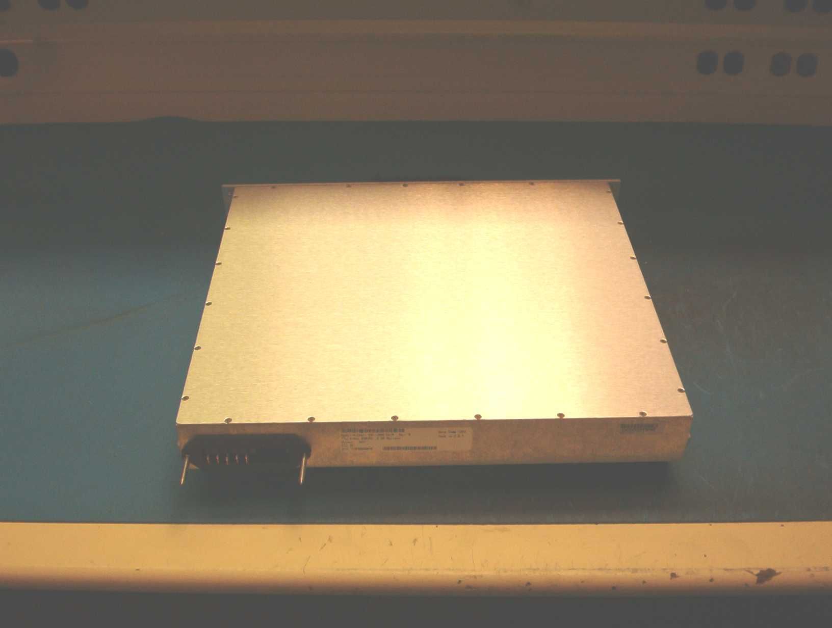
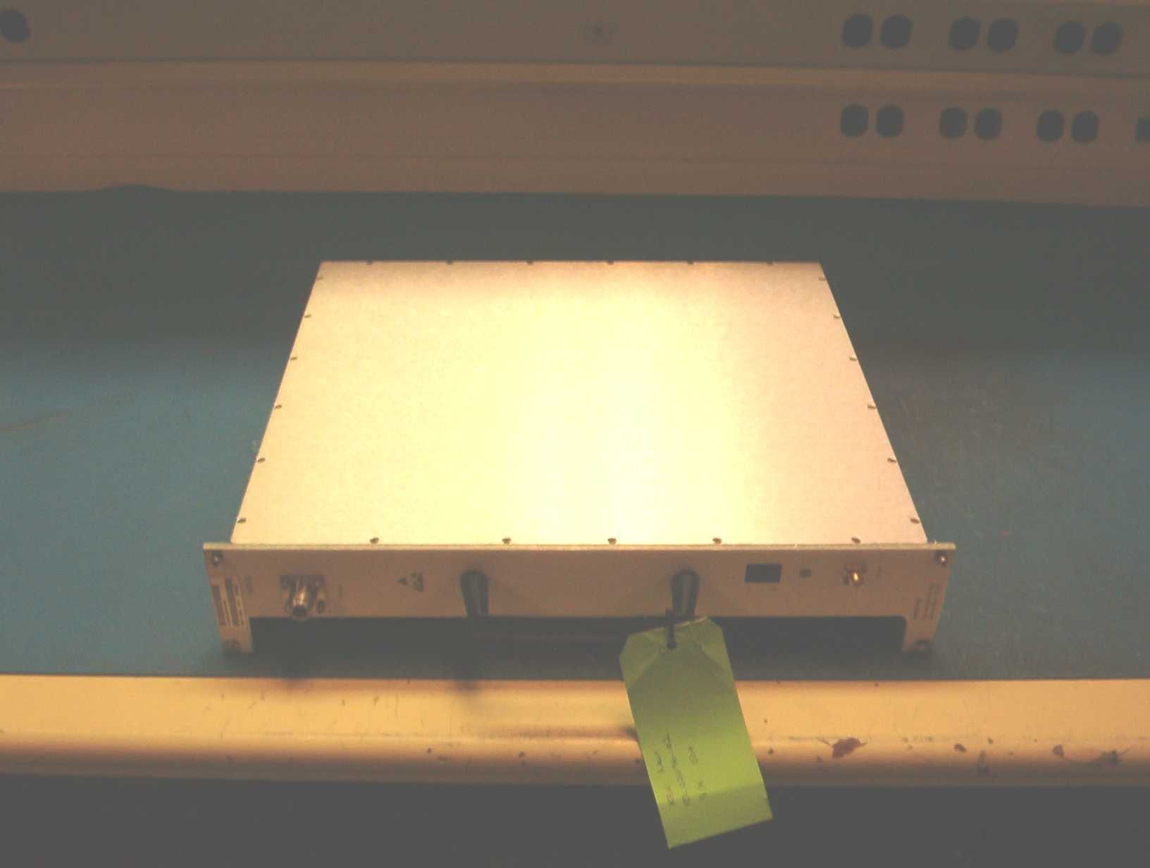
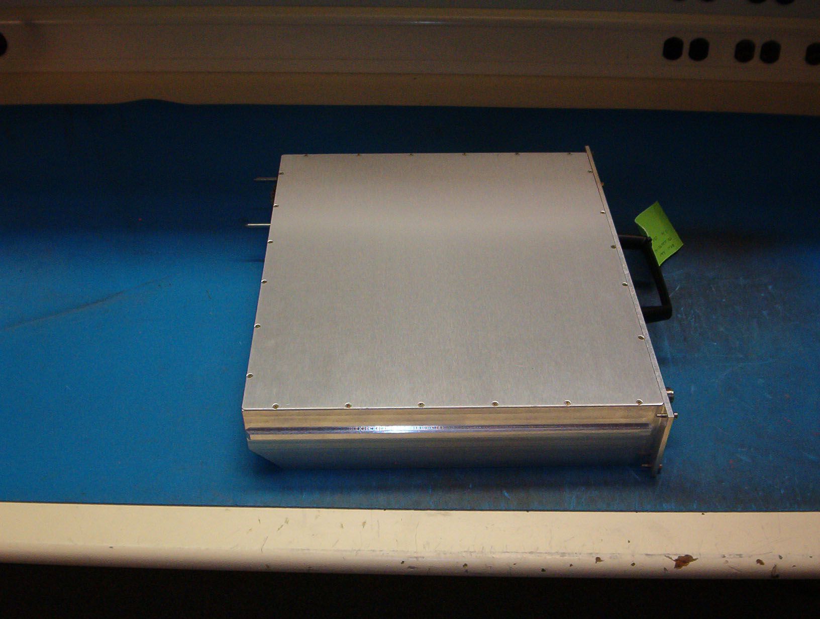
Test Setup Photos
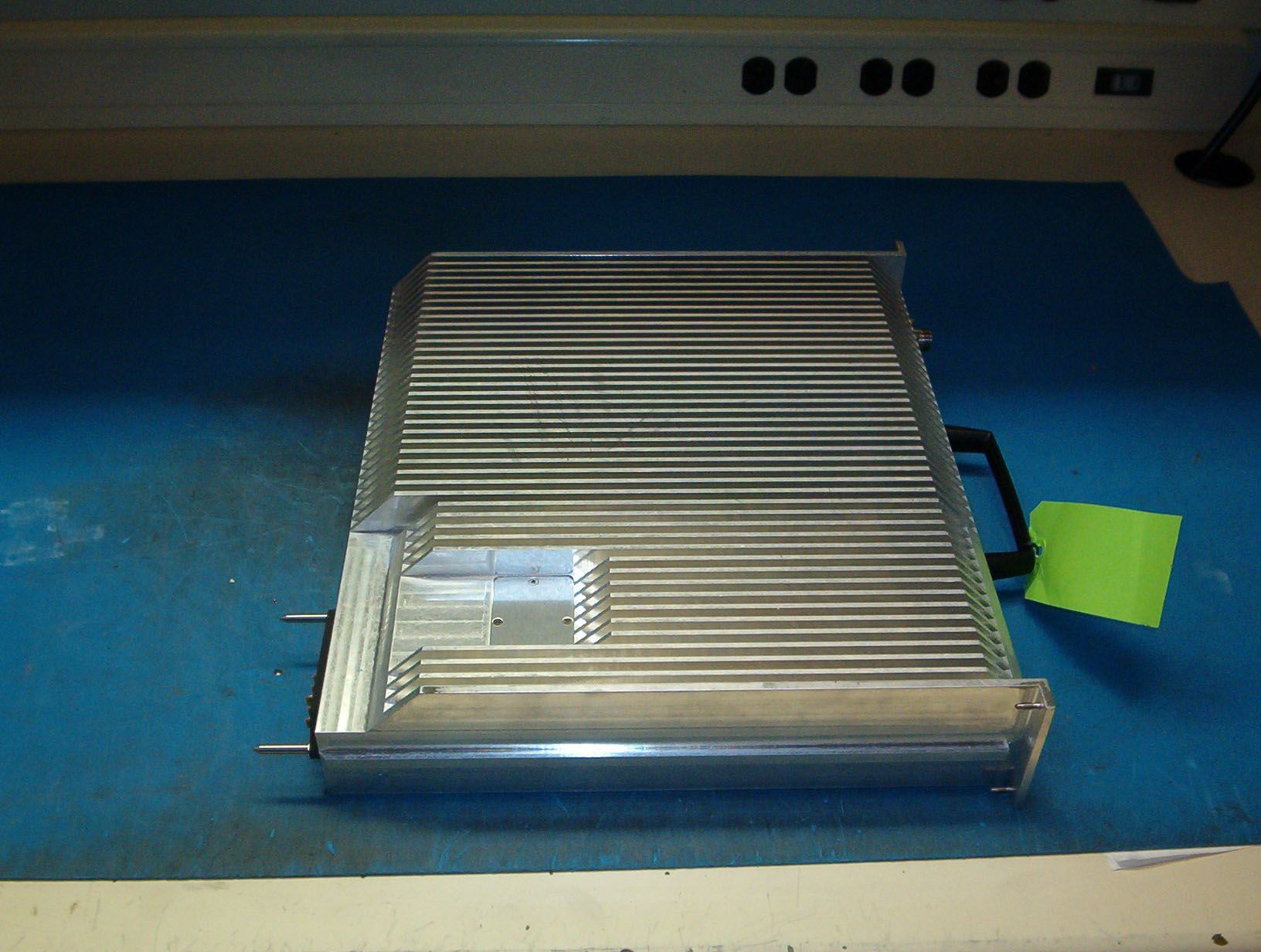
Radiated Emissions - Front View Radiated Emissions - Back View Horn Horn Loop Mains Conducted Emissions - Front View Mains Conducted Emissions - Side View
Contact Information
Applicant
Jeff Dale(Principal Reliability Engineer)
Technical Contact
CKC Laboratories, IncMary Ellen Clayton
[email protected]209-966-5240
5473A Clouds Rest · Mariposa, California · United States
Non-Technical Contact
CKC Laboratories, IncMary Ellen Clayton
[email protected]209-966-5240
Test Firm
CKC Laboratories, Inc.Steve Behm
Technical Specifications
| # | Rule Parts | Frequency Range | Power Output | Emission | Tolerance |
|---|---|---|---|---|---|
| 1 | 24 | 1.93 GHz - 1.99 GHz | 54 W | F9W | Amp |
Other Applications from Powerwave Technologies Inc

E675JS0123
Nov 03, 2011Multi-carrier RF Power Amplifier
Equipment Class
AMP - Amplifier
E675JS0120
Aug 26, 2010Nexus Dual Band Repeater
Equipment Class
TNB - Licensed Non-Broadcast Station Transmitter
E675JS0119
Aug 01, 2010Nexus Dual Band Repeater
Equipment Class
PCB - PCS Licensed Transmitter
E675JS0118
Jul 26, 2010Nexus Dual Band Repeater
Equipment Class
PCB - PCS Licensed Transmitter
E675JS0096
Jan 10, 2008Wideband Radio Head
Equipment Class
TNB - Licensed Non-Broadcast Station Transmitter