E675JS0080RF Broadband Amplifier Module, Model ASY00116
Powerwave Technologies Inc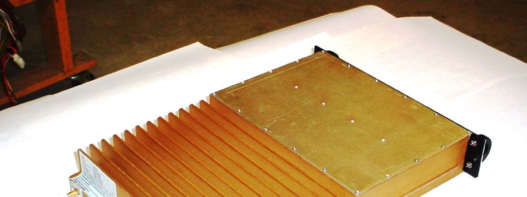
Click to zoom
Application Details
- Equipment Class
- PCB - PCS Licensed Transmitter
- Date of Grant
- Oct 27, 2005
- Application Purpose
- Original Equipment
- Date of Application
- Oct 27, 2005
- Equipment Note
- RF Broadband Amplifier Module, Model ASY00116
- Frequency Range
- 940.00000000 - 944.00000000
- Company
- Powerwave Technologies Inc
- Country
- United States
Documents & Files
Document Text
Text extracted from the exhibit documents filed with the FCC. Open a document above to read the original.
Users Manual
DCM000000054 Rev Q October 2005 LinkNet™ LNKA100, LNKF400, LNKA800 RF BROADBAND AMPLIFIER MODULES User, Installation, Operation, and Maintenance Manual © 2005 Powerwave Technologies Incorporated. All rights reserved. Powerwave Technologies, and the Powerwave logo are registered trademarks. This Powerwave product is intended only for installation in a RESTRICTED ACCESS LOCATION and is designed to operate within the Normal Operating (typical operating) ranges or conditions specified in this document. Operation of this equipment beyond the specified ranges in this document may cause: 1. Spurious emissions that violate regulatory requirements. 2. The equipment to be automatically removed from service when maximum thresholds are exceeded. 3. The equipment to not perform in accordance with its specifications. It is the Operator's responsibility to ensure this equipment is properly installed and operated within Powerwave operating specifications to obtain proper performance from the equipment and to comply with regulatory requirements. Warnings, Cautions, and Notes Warnings, Cautions, and Notes Warnings, cautions, and notes are found throughout this manual where applicable. The associated icons are used to quickly identify a potential condition that could result in the consequences described below if precautions are not taken. Notes clarify and provide additional information to assist the user. Warning This warning symbol means danger. You are in a situation that could cause bodily injury. Before you work on any equipment, be aware of the hazards involved with electrical and RF circuitry and be familiar with standard practices for preventing accidents. Caution This caution symbol means reader be careful. In this situation, the user might do something that could result in equipment damage or loss of data. Note This note symbol means reader take note. Notes contain helpful suggestions or references to material not covered in the document. Procedures are not contained in notes. DCM000000054 Rev Q i Revision Record ii DCM000000054 Rev Q Revision Record Revision Letter Date of Change Reason for Change Q October 2005 Added 700 MHz models, misc. corrections P July 2005 Converted Kaval Rev 14 to Powerwave Format DCM000000054 Rev Q iii TABLE OF CONTENTS Chapter 1 Theory of Operation 1 Introduction.................................................................................................................... 1-1 1.1 OVERVIEW......................................................................................................................... 1-1 1.2 MODELS............................................................................................................................ 1-1 1.3 BLOCK DIAGRAM................................................................................................................ 1-2 1.4 MODULE SPECIFICATIONS................................................................................................... 1-3 Chapter 2 - Operation 2 Introduction.................................................................................................................... 2-1 2.1 SOFTWARE SET-UP............................................................................................................ 2-1 2.2 CONFIGURATION................................................................................................................ 2-1 2.3 DERATING CHART.............................................................................................................. 2-2 2.4 POWER ON SELF TEST (POST).......................................................................................... 2-2 2.5 FAULT INDICATIONS............................................................................................................ 2-3 2.6 NORMAL OPERATION.......................................................................................................... 2-3 Chapter 3 - Antenna Installation 3 Introduction.................................................................................................................... 3-1 3.1 ANTENNA INSTALLATION..................................................................................................... 3-1 3.2 FCC INFORMATION TO USERS............................................................................................ 3-2 Chapter 4 - Return for Service 4 Introduction.................................................................................................................... 4-1 4.1 RETURN FOR SERVICE PROCEDURE................................................................................... 4-1 4.1.1 Obtaining An RMA........................................................................................................... 4-1 4.1.2 Repackaging For Shipment............................................................................................. 4-1 4.2 PARTS AND ACCESSORIES.................................................................................................. 4-1 Table of Figures iv DCM000000054 Rev Q TABLE OF FIGURES Figure 1 Block Diagram LNKA RF Module................................................................................... 1-2 Figure 2 LNKA Faceplate............................................................................................................. 2-3 TABLE OF TABLES Table 1 LNKA Module Family....................................................................................................... 1-1 Table 2 LNKA Module Specifications........................................................................................... 1-3 Table 3 LNKA Factory Set Options.............................................................................................. 2-1 DCM000000054 Rev Q 1-1 Chapter 1 Theory of Operation 1 Introduction This manual contains information and procedures for installation, operation, maintenance, and troubleshooting of the LNKA Modules. The manual is organized into the following ch…
Text truncated - open the document above for the full version.
Users Manual
FCC Information to Users ANTENNA INSTALLATION CAUTION ALL ANTENNA INSTALLATION IS TO BE PERFORMED BY QUALIFIED TECHNICAL PERSONNEL ONLY. ANTENNA INSTALLATION INSTRUCTIONS AND LOCATIONS ARE FOR THE PURPOSE OF SATISFYING FCC RF EXPOSURE COMPLIANCE REQUIREMENTS, AND ARE NOT OPTIONAL. ALL ROOF TOP ANTENNA INSTALLATION MUST BE SUCH THAT NO PERSON CAN TOUCH THE ANTENNA, OR APPROACH CLOSER THAN 10 METERS. ALL IN-BUILDING ANTENNAE INSTALLATIONS MUST BE SUCH THAT NO PERSON CAN TOUCH THE ANTENNAE, OR APPROACH CLOSER THAN 0.2 METERS. 3.2 FCC Information to Users • This equipment has been tested and found to comply with the limits for a Class A digital device, pursuant to Part 15 of the FCC Rules. These limits are designed to provide reasonable protection against harmful interference when the equipment is operated in a commercial environment. This equipment generates, uses, and can radiate radio frequency energy and, if not installed and used in accordance with the instruction manual, may cause harmful interference to radio communications. Operation of this equipment in a residential area is likely to cause harmful interference in which case the user will be required to correct the interference at his own expense. CAUTION CHANGES OR MODIFICATIONS NOT EXPRESSLY APPROVED BY POWERWAVE TECHNOLOGIES INC. COULD VOID THE USER’S AUTHORITY TO OPERATE THE EQUIPMENT. 3-2 DCM000000054 Rev Q
Cover Letter(s)
15 Allstate Pkwy, Suite 300, MARKHAM, ON, L3R 5B4, CANADA Tel: (905) 940-1400 Toll Free: 1-888-865-2825 Fax: (905) 946-3392 September 29, 2005 Federal Communications Commission Equipment Authorization Branch 7435 Oakland Mills Rd. Columbia, MD, 21046, USA Subject: CONFIDENTIALTY REQUEST Dear Sir or Madam; Powerwave Technologies respectfully requests confidentiality of certain materials provided with the submission of the 700-900 MHz Linear Amplifier ASY00116 under FCC ID: E675JS0080 in accordance with FCC Regulations 0.459. The confidentiality request applies to the schematic diagrams, SCH000000081, SCH000000095, SCH000000099, and the associated Parts Lists, Block diagrams and Theory of Operation contained in Exhibit 2. The 700-900 MHz Linear Amplifier and associated controllers have been developed at considerable effort and expense by Powerwave Technologies. These items are considered as Trade Secrets and therefore public access to the proprietary material could possibly result in duplication of equipment that could severely damage the company’s business advantage. I appreciate your assistance in this manner. Yours sincerely, Name: Stan Habinski, P.Eng. Signature: _________________________________ Title: Director – Research & Development Date: September 29, 2005 z Page 1
Cover Letter(s)
October 10, 2005 TIMCO ENGINEERING INC. P.O. Box 370 849 N.W. State Road 45 Newberry, Florida Subject: Type Acceptance Application under FCC 47 CFR, Parts 2, 27 and 90 (Subpart I & R) - Non-Broadcast RF Linear Amplifier Operating in the frequency 746-944 MHz. Applicant: Powerwave Technologies Inc. Product: RF Broadband Amplifier Module Model: ASY00116 FCC ID: E675JS0080 Dear Sir/Madam, This application is for Limited Modular Approval and the end product should comply with FCC Part 15B unintentional AC Powerline Conducted Emission requirement. As appointed agent for Powerwave Technologies Inc., we would like to submit the application for FCC Certification for the above Product. Please review all necessary files uploaded to TIMCO Upload Web Site. If you have any queries, please do not hesitate to contact us Yours truly, Tri Minh Luu, P. Eng., V.P., Engineering TML/DH Encl. UltraTech Group of Labs 31040/SIT C-1376 46390-2049 200093-0 2 00-034 SL2-IN-E-1119R 3000 Bristol Circle, Oakville, Ontario, Canada L6H 6G4 Tel.: (905) 829-1570 Fax.: (905) 829-8050 Website: www.ultratech-labs.com Email: [email protected]
Cover Letter(s)
TIMCO ENGINEERING INC From: Dharmajit Solanki [[email protected]] Sent: Friday, October 28, 2005 10:02 AM To: 'tei' Subject: FW: TIMCO-TCB/Request for additional info - POWERWAVE TECHNOLOGIES INC. - FCC ID: E675JS0080 Importance: High Dear Bruno, Pl find our reply for your question as per below. Also find attached revised/information documents. 1. The antenna seperation warning distance for 20dBi gain antenna is already mentioned in the user manual. Pl check Page 3-2 of user manual, also attached file for ready reference. 2. Revised Form 731 is attached. 3. Pl find revised report attched showing compliance with Part 27. 4. We hereby confirm that we have notified the applicant about the FCC requirement- boosters must meet all criteria stated in Sections 90.219 for related booster/in-building operations. Sincerely, Dharmajit Solanki UltraTech Engineering Labs INc. Canada From: Tri Luu [mailto:[email protected]] Sent: Wednesday, October 26, 2005 10:40 AM To: Dhamajit Solanki Subject: Fw: TIMCO-TCB/Request for additional info - POWERWAVE TECHNOLOGIES INC. - FCC ID: E675JS0080 Importance: High DJ, please take care this. ----- Original Message ----- From: Bruno To: Tri M. Luu Sent: Tuesday, October 25, 2005 5:54 PM Subject: TIMCO-TCB/Request for additional info - POWERWAVE TECHNOLOGIES INC. - FCC ID: E675JS0080 TIMCO ENGINEERING INC. TCB & FCB 849 NW State Road 45 FCC Approvals file:///U|/P/POWER_E67/2152UC5/cust%20reply%20-%2051028.htm (1 of 3)11/4/2005 3:23:16 AM TIMCO ENGINEERING INC Newberry, Florida 32669 Industry Canada Approvals http://www.timcoengr.com Notified Body for Europe 888.472.2424 F 352.472.2030 email: [email protected] 10/25/2005 MR. TRI M. LUU ULTRATECH ENGINEERING LABS, INC. 1-877-765-4173 905-829-8050 [email protected] SUBJECT: POWERWAVE TECHNOLOGIES INC. - FCC ID: E675JS0080 REFERENCE: JOB 2152UC5 Dear MR. LUU: This application is on hold until these questions are resolved. Please answer all question(s) together and only respond to [email protected]. Any other method will cause unnecessary delay. DO NOT HIT REPLY! Responses should also contain the Reference information, as shown at the top of this message. If acceptable response is not received within 2 week the job will be closed & there will be additional charges to reopen. Based upon our review of this application we have the following questions: 1. RF exposure – User manual: Please include the required separation distances for outdoor antenna installation according to RF exposure calculations for a 20dBi maximum antenna gain. 2. This device is a bi-directional amplifier/repeater/ in-building radiation system. AMP class is for ERFPA (external RF power amplifier) only. This device should be filed under equipment class TNB. Please revise form 731. 3. This application was made for part 27. Please justify compliance with part 27 technical requirements. 4. Please confirm that the applicant is informed of the following sections: boosters must meet all criteria stated in Sections 90.219 for related booster/in-building operations. Sincerely, Bruno Clavier file:///U|/P/POWER_E67/2152UC5/cust%20reply%20-%2051028.htm (2 of 3)11/4/2005 3:23:16 AM TIMCO ENGINEERING INC file:///U|/P/POWER_E67/2152UC5/cust%20reply%20-%2051028.htm (3 of 3)11/4/2005 3:23:16 AM
Cover Letter(s)
July 25, 2006 TIMCO ENGINEERING INC. P.O. Box 370 849 N.W. State Road 45 Newberry, Florida Subject: Type Acceptance Application under FCC 47 CFR, Parts 2, 22, 24, 27, 90 & 101 - Non-Broadcast RF Linear Amplifier Operating in the frequency 746-944 MHz. Applicant: Powerwave Technologies Inc. Product: RF Broadband Amplifier Module Model: ASY00116 FCC ID: E675JS0080 Dear Sir/Madam, As appointed agent for Powerwave Technologies Inc., We would like to submit the revised test report with additional test data as requested by FCC during the certification audit of the above Product. As Powerwave Technologies will not provide separate band-pass filters for different operating frequency sub-bands, hence all units are electrically identical to each other. If you have any queries, please do not hesitate to contact us. Yours truly, Tri Minh Luu, P. Eng., V.P., Engineering TML/DH Encl. UltraTech Group of Labs 31040/SIT C-1376 46390-2049 200093-0 2 00-034 SL2-IN-E-1119R 3000 Bristol Circle, Oakville, Ontario, Canada L6H 6G4 Tel.: (905) 829-1570 Fax.: (905) 829-8050 Website: www.ultratech-labs.com Email: [email protected]
External Photos
ANNEX 2 – EXTERNAL PHOTOGRAPHS Powerwave Technologies Inc. RF Broadband Amplifier Module Model No.: LNKA700/800 FCC ID: E675JS0080 IC: 2868C-5JS0080 A2 - 1 ANNEX 2 – EXTERNAL PHOTOGRAPHS Powerwave Technologies Inc. RF Broadband Amplifier Module Model No.: LNKA700/800 FCC ID: E675JS0080 IC: 2868C-5JS0080 A2 - 2
ID Label/Location Info
15 Allstate Parkway, Markham, Ontario, L3R 5B4 www.pwav.com, 905-940-1400, 905-946-3392 FAX LAB000000022 FCC-IC LABEL FOR 700-900 MHz Linear Amplifier October 12, 2005 Revision E Linear Amplifier ASY00116 FCC ID E675JS0080 IC: 2868C-5JS0080 Model LNKAy00-z or SBy-DECK Serial number Frequency Range MHz This device complies with Part 15 of the FCC Rules. Operation is subject to the following two conditions: (1) this device may not cause harmful interference and (2) this device must accept any interference received, including interference that may cause undesired operation. Manufactured in Canada by POWERWAVE TECHNOLOGIES INC. Print the above on self-adhesive metalized polyester labels with the correct information from below. Add the serial number as well. Install the LNKA labels on the rear of the housing as shown in DCA000000086 or SB DECK label on side of the RF Deck as shown in DCA000000325. The FCC part 15 label portion does not need to be added to the RF Deck. ASY00116 model LSM model # Frequency (MHz) ASY00116-A LNKA800-A 806-824 ASY00116-B LNKA800-B 851-869 ASY00116-E LNKA800-C 824-849 ASY00116-F LNKA800-D 869-894 ASY00116-G LNKA800-E 896-902 ASY00116-H LNKA800-G 935-941 ASY00116-I LNKA800-F 928-941 ASY00116-J LNKA700-A 762-776 ASY00116-K LNKA700-B 792-806 Uplink amplifier Downlink amplifier RF DECK model Frequency (MHz) ASY00116-A ASY00116-B SB800-DECK-SMR 806-824/851-869 ASY00116-E ASY00116-F SB800-DECK-CELL 824-849/869-894 ASY00116-G ASY00116-H SB900-DECK-PAG 896-902/935-941 ASY00116-G ASY00116-I SB900-DECK-PAGE 896-902/928-941 ASY00116-K ASY00116-J SB700-DECK-PS 792-806/762-776 Placement of the Model / FCC / Industry Canada Label LAB000000022: This two part label is adhered to the 'rear' of the Module as shown... DCA000000086 Page 10 of 10
Internal Photos
ANNEX 3 – INTERNAL PHOTOGRAPHS Powerwave Technologies Inc. RF Broadband Amplifier Module ASY00116 Model No.: LNKA700/800 FCC ID: E675JS0080 IC: 2868C-5JS0080 A3 - 1 ANNEX 3 – INTERNAL PHOTOGRAPHS Powerwave Technologies Inc. RF Broadband Amplifier Module ASY00116 Model No.: LNKA700/800 FCC ID: E675JS0080 IC: 2868C-5JS0080 A3 - 2 ANNEX 3 – INTERNAL PHOTOGRAPHS Powerwave Technologies Inc. RF Broadband Amplifier Module ASY00116 Model No.: LNKA700/800 FCC ID: E675JS0080 IC: 2868C-5JS0080 A3 - 3 ANNEX 3 – INTERNAL PHOTOGRAPHS Powerwave Technologies Inc. RF Broadband Amplifier Module ASY00116 Model No.: LNKA700/800 FCC ID: E675JS0080 IC: 2868C-5JS0080 A3 - 4 Amplifier ASY00116 ANNEX 3 – INTERNAL PHOTOGRAPHS Powerwave Technologies Inc. RF Broadband Amplifier Module ASY00116 Model No.: LNKA700/800 FCC ID: E675JS0080 IC: 2868C-5JS0080 A3 - 5 Amplifier ASY00116 ANNEX 3 – INTERNAL PHOTOGRAPHS Powerwave Technologies Inc. RF Broadband Amplifier Module ASY00116 Model No.: LNKA700/800 FCC ID: E675JS0080 IC: 2868C-5JS0080 A3 - 6 Amplifier ASY00116 ANNEX 3 – INTERNAL PHOTOGRAPHS Powerwave Technologies Inc. RF Broadband Amplifier Module ASY00116 Model No.: LNKA700/800 FCC ID: E675JS0080 IC: 2868C-5JS0080 A3 - 7 Controller ANNEX 3 – INTERNAL PHOTOGRAPHS Powerwave Technologies Inc. RF Broadband Amplifier Module ASY00116 Model No.: LNKA700/800 FCC ID: E675JS0080 IC: 2868C-5JS0080 A3 - 8 Controller
Parts List/Tune Up Info
There is no Tuning for this product. It is calibrated when it undergoes Factory Testing. When installed, the Amplifier is set up by software (see the User Manuals DCM000000054 and DCM000000105) for the desired Gain and AGC setting. The combination of these two settings ensures that the Maximum Power and RF De-Rating requirements are met.
RF Exposure Info
DCM000000054 Rev Q 3-1 Chapter 3 Antenna Installation 3 Introduction This chapter contains antenna installation and warning information for the LNKA Modules. 3.1 Antenna Installation • • • • • • All antenna installation to be performed by qualified technical personnel only. Antenna installation instructions and locations below are for the purpose of satisfying FCC RF Exposure Compliance requirements. Note! If multiple LinkNet™ Modules are used, the Instructions below apply to the composite power output of all Modules when transmitting simultaneously. The Roof Top Antenna or Antennae for linking to the Donor Site(s) is/are directional (high gain) Antennae, fixed-mounted physically on the side or top of a building, or on a tower. The Antenna Gain must be no more than 20 dBi. Note! If multiple LinkNet™ Modules are used with output combiners into any one Antenna, and/or multiple Antennae are used on one Roof Top, then the sum of composite powers into all Roof Top Antennae must not exceed 20 Watts maximum. The Roof Top Antennae location should be such that only qualified technical personnel can access it, and that under normal operating conditions no other person can touch the antenna, or approach within 10 meters of the antenna. For the Cellular Uplink Band (824-849 MHz) the Roof Top Antenna or Antennae for linking to the Donor Site(s) has the added restriction that the Effective Radiated Power (ERP) must not exceed 7 Watts (+38 dBm). Thus, if the AGC is set (as per the Carrier Derating Chart) to +28 dBm as an example, the maximum allowed antenna gain must be no more than 10 dBi. The In-Building Antenna connection is via a coaxial cable distribution system with signal taps at various points connected to the fixed-mounted Indoor Antennae. The Indoor Antennae are simple 1/4 wavelength (0 dB Gain) types. They are used with Powerwave Technologies’ 12, 16, or 20 dB cable taps. As such the maximum EIRP will be at the first tapped antenna, which will be 12 dB below the maximum signal level of the LinkNet™ (+40 dBm); +28 dBm, or 0.63 Watts EIRP. These antennae are to be installed such that no person can touch the antenna, or approach within 0.2 Meters. Note! If multiple LinkNet™ Modules are used with output combiners, then the composite power output of all Modules transmitting simultaneously must meet this maximum EIRP requirement. Please consult Powerwave Technologies Inc. for assistance as required. FCC Information to Users ANTENNA INSTALLATION CAUTION ALL ANTENNA INSTALLATION IS TO BE PERFORMED BY QUALIFIED TECHNICAL PERSONNEL ONLY. ANTENNA INSTALLATION INSTRUCTIONS AND LOCATIONS ARE FOR THE PURPOSE OF SATISFYING FCC RF EXPOSURE COMPLIANCE REQUIREMENTS, AND ARE NOT OPTIONAL. ALL ROOF TOP ANTENNA INSTALLATION MUST BE SUCH THAT NO PERSON CAN TOUCH THE ANTENNA, OR APPROACH CLOSER THAN 10 METERS. ALL IN-BUILDING ANTENNAE INSTALLATIONS MUST BE SUCH THAT NO PERSON CAN TOUCH THE ANTENNAE, OR APPROACH CLOSER THAN 0.2 METERS. 3.2 FCC Information to Users • This equipment has been tested and found to comply with the limits for a Class A digital device, pursuant to Part 15 of the FCC Rules. These limits are designed to provide reasonable protection against harmful interference when the equipment is operated in a commercial environment. This equipment generates, uses, and can radiate radio frequency energy and, if not installed and used in accordance with the instruction manual, may cause harmful interference to radio communications. Operation of this equipment in a residential area is likely to cause harmful interference in which case the user will be required to correct the interference at his own expense. CAUTION CHANGES OR MODIFICATIONS NOT EXPRESSLY APPROVED BY POWERWAVE TECHNOLOGIES INC. COULD VOID THE USER’S AUTHORITY TO OPERATE THE EQUIPMENT. 3-2 DCM000000054 Rev Q
Test Report
RF Broadband Amplifier Module Model No.: ASY00116 FCC ID: E675JS0080 Applicant: Powerwave Technologies Inc. 1805 East St. Andrew Place Santa Ana, CA USA, 92705 Tested in Accordance With Federal Communications Commission (FCC) 47 CFR, Parts 2, 27 and 90 (Subpart I & R) UltraTech's File No.: KTI044_FCC90 This Test report is Issued under the Authority of Tri M. Luu, Professional Engineer, Vice President of Engineering UltraTech Group of Labs Date: October 10, 2005 Report Prepared by: Dharmajit Solanki Tested by: Wayne Wu, EMI/RFI Technician Issued Date: October 10, 2005 Test Dates: Sep. 02 – 10, 2005 The results in this Test Report apply only to the sample(s) tested, and the sample tested is randomly selected. This report must not be used by the client to claim product endorsement by NVLAP or any agency of the US Government. UltraTech 3000 Bristol Circle, Oakville, Ontario, Canada, L6H 6G4 Tel.: (905) 829-1570 Fax.: (905) 829-8050 Website: www.ultratech-labs.com , Email: [email protected], Email: [email protected] 2 31040/SIT C-1376 46390-2049 200093-0 SL2-IN-E-1119R 00-034 FCC PARTS 2, 27 and 90(Subpart I & R), NON-BROADCAST RADIO TRANSCEIVERS Contents i RF Broadband Amplifier Module, Model ASY00116 FCC ID: E675JS0080 ULTRATECH GROUP OF LABS File #: KTI044_FCC90 3000 Bristol Circle, Oakville, Ontario, Canada L6H 6G4 October 10, 2005 Tel. #: 905-829-1570, Fax. #: 905-829-8050, Email: [email protected] , Website: http://www.ultratech-labs.com All test results contained in this engineering test report are traceable to National Institute of Standards and Technology (NIST) TABLE OF CONTENTS EXHIBIT 1. INTRODUCTION ......................................................................................................................................... 1 1.1. SCOPE......................................................................................................................................................................... 1 1.2. RELATED SUBMITTAL(S)/GRANT(S)................................................................................................................... 1 1.3. NORMATIVE REFERENCES ................................................................................................................................... 1 EXHIBIT 2. PERFORMANCE ASSESSMENT .............................................................................................................. 2 2.1. CLIENT INFORMATION .......................................................................................................................................... 2 2.2. EQUIPMENT UNDER TEST (EUT) INFORMATION............................................................................................. 2 2.3. EUT’S TECHNICAL SPECIFICATIONS.................................................................................................................. 3 2.4. LIST OF EUT’S PORTS ............................................................................................................................................. 3 2.5. ANCILLARY EQUIPMENT ...................................................................................................................................... 3 2.6. DRAWING OF TEST SETUP .................................................................................................................................... 4 EXHIBIT 3. EUT OPERATING CONDITIONS AND CONFIGURATIONS DURING TESTS ............................... 5 3.1. CLIMATE TEST CONDITIONS................................................................................................................................ 5 3.2. OPERATIONAL TEST CONDITIONS & ARRANGEMENT FOR TEST SIGNALS............................................. 5 EXHIBIT 4. SUMMARY OF TEST RESULTS ............................................................................................................... 6 4.1. LOCATION OF TESTS .............................................................................................................................................. 6 4.2. APPLICABILITY & SUMMARY OF EMISSION TEST RESULTS @ FCC PART 2, 27 & 90(SUBPART I & R) 6 4.3. MODIFICATIONS INCORPORATED IN THE EUT FOR COMPLIANCE PURPOSES ....................................... 7 4.4. DEVIATION OF STANDARD TEST PROCEDURES ............................................................................................. 7 EXHIBIT 5. MEASUREMENTS, EXAMINATIONS & TEST DATA FOR EMC EMISSIONS............................... 8 5.1. TEST PROCEDURES................................................................................................................................................. 8 5.2. MEASUREMENT UNCERTAINTIES ...................................................................................................................... 8 5.3. MEASUREMENT EQUIPMENT USED: .................................................................................................................. 8 5.4. ESSENTIAL/PRIMARY FUNCTIONS AS DECLARED BY THE MANUFACTURER:....................................... 8 5.5. RF POWER OUTPUT & INTERMODULATION @ FCC 2.1046, 27.50(B), 90.541 & 90.635 .............................. 9 5.6. RF EXPOSURE REQUIREMENTS @ 1.1310 & 2.1091 ........................................................................................ 20 5.7. 99% OBW, 20 DB BW @ FCC 2.1049 & 90.210 .................................................................................................... 24 5.8. TRANSMITTER ANTENNA POWER SPURIOUS/HARMONIC CONDUCTED EMISSIONS @ 27.53(C)&(D), 90.210, 90.543(C), 2.1057 & 2.1051 ........................................................................................................................ 57 5.9. TRANSMITTER SPURIOUS/HARMONIC RADIATED EMISSIONS @ 27.53(C)&(D), 90.210, 90.543(C), 2.1057 & 2.1053........................................................................................................................................................ 80 E…
Text truncated - open the document above for the full version.
Test Report
RF Broadband Amplifier Module Model No.: ASY00116 FCC ID: E675JS0080 Applicant: Powerwave Technologies Inc. 1805 East St. Andrew Place Santa Ana, CA USA, 92705 Tested in Accordance With Federal Communications Commission (FCC) 47 CFR, Parts 2, 22, 24, 27, 90 & 101 UltraTech's File No.: KTI058_FCC90 This Test report is Issued under the Authority of Tri M. Luu, Professional Engineer, Vice President of Engineering UltraTech Group of Labs Date: July 25, 2006 Report Prepared by: Dharmajit Solanki Tested by: Wayne Wu, EMI/RFI Technician Issued Date: July 25, 2006 Test Dates: Sep. 02 – 10, 2005 & July 03 – 12, 2006 The results in this Test Report apply only to the sample(s) tested, and the sample tested is randomly selected. This report must not be used by the client to claim product endorsement by NVLAP or any agency of the US Government. UltraTech 3000 Bristol Circle, Oakville, Ontario, Canada, L6H 6G4 Tel.: (905) 829-1570 Fax.: (905) 829-8050 Website: www.ultratech-labs.com , Email: [email protected], Email: [email protected] 2 31040/SIT C-1376 46390-2049 200093-0 SL2-IN-E-1119R 00-034 FCC PARTS 2, 22, 24, 27, 90 and 101, NON-BROADCAST RADIO TRANSCEIVERS Contents i RF Broadband Amplifier Module, Model: ASY00116 FCC ID: E675JS0080 ULTRATECH GROUP OF LABS File #: KTI058_FCC90 3000 Bristol Circle, Oakville, Ontario, Canada L6H 6G4 July 25, 2006 Tel. #: 905-829-1570, Fax. #: 905-829-8050, Email: [email protected] , Website: http://www.ultratech-labs.com All test results contained in this engineering test report are traceable to National Institute of Standards and Technology (NIST) TABLE OF CONTENTS EXHIBIT 1. INTRODUCTION ......................................................................................................................................... 1 1.1. SCOPE......................................................................................................................................................................... 1 1.2. RELATED SUBMITTAL(S)/GRANT(S)............................................................................................................…
Text truncated - open the document above for the full version.
Contact Information
Applicant
Jeff Dale(Principal Reliability Engineer)
Test Firm
UltraTech Engineering Labs Inc.Tri Luu
Technical Specifications
| # | Rule Parts | Frequency Range | Power Output | Emission | Tolerance |
|---|---|---|---|---|---|
| 52 | 101C,22,24D | 940 MHz - 944 MHz | 1.41 W | F2D | Amp |
Other Applications from Powerwave Technologies Inc

E675JS0123
Nov 03, 2011Multi-carrier RF Power Amplifier
Equipment Class
AMP - Amplifier
E675JS0120
Aug 26, 2010Nexus Dual Band Repeater
Equipment Class
TNB - Licensed Non-Broadcast Station Transmitter
E675JS0119
Aug 01, 2010Nexus Dual Band Repeater
Equipment Class
PCB - PCS Licensed Transmitter
E675JS0118
Jul 26, 2010Nexus Dual Band Repeater
Equipment Class
PCB - PCS Licensed Transmitter
E675JS0096
Jan 10, 2008Wideband Radio Head
Equipment Class
TNB - Licensed Non-Broadcast Station Transmitter