E675JS0083LINKNET LNKF100 SERVICE
Powerwave Technologies Inc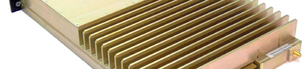
Click to zoom
Application Details
- Equipment Class
- TNB - Licensed Non-Broadcast Station Transmitter
- Date of Grant
- Feb 16, 2006
- Application Purpose
- Original Equipment
- Date of Application
- Feb 16, 2006
- Equipment Note
- LINKNET LNKF100 SERVICE
- Frequency Range
- 136.00000000 - 174.00000000
- Company
- Powerwave Technologies Inc
- Country
- United States
Documents & Files
Document Text
Text extracted from the exhibit documents filed with the FCC. Open a document above to read the original.
Users Manual
D044-13432 Rev A December 2005 LinkNet™ LNKF100 RF MODULES User, Installation, Operation, and Maintenance Manual © 2005 Powerwave Technologies Incorporated. All rights reserved. Powerwave Technologies, and the Powerwave logo are registered trademarks. This Powerwave product is intended only for installation in a RESTRICTED ACCESS LOCATION and is designed to operate within the Normal Operating (typical operating) ranges or conditions specified in this document. Operation of this equipment beyond the specified ranges in this document may cause: 1. Spurious emissions that violate regulatory requirements. 2. The equipment to be automatically removed from service when maximum thresholds are exceeded. 3. The equipment to not perform in accordance with its specifications. It is the Operator's responsibility to ensure this equipment is properly installed and operated within Powerwave operating specifications to obtain proper performance from the equipment and to comply with regulatory requirements. Warnings, Cautions, and Notes Warnings, Cautions, and Notes Warnings, cautions, and notes are found throughout this manual where applicable. The associated icons are used to quickly identify a potential condition that could result in the consequences described below if precautions are not taken. Notes clarify and provide additional information to assist the user. Warning This warning symbol means danger. You are in a situation that could cause bodily injury. Before you work on any equipment, be aware of the hazards involved with electrical and RF circuitry and be familiar with standard practices for preventing accidents. Caution This caution symbol means reader be careful. In this situation, the user might do something that could result in equipment damage or loss of data. Note This note symbol means reader take note. Notes contain helpful suggestions or references to material not covered in the document. Procedures are not contained in notes. D044-13432 Rev A i Revision Record ii D044-13432 Rev A Revision Record Revision Letter Date of Change Reason for Change A Dec 2005 Initial Release D044-13432 Rev A iii TABLE OF CONTENTS Chapter 1.............................................................................................................1 Theory of Operation............................................................................................1 1 Introduction................................................................................................1 1.1 OVERVIEW.......................................................................................................................... 1 1.2 MODELS............................................................................................................................. 1 1.3 BLOCK DIAGRAM................................................................................................................ 2 1.4 MODULE SPECIFICATIONS.................................................................................................... 3 ALSO CONSULT THE MAIN LINKNET™ MANUAL DCM000000008..................................................... 3 Chapter 2.............................................................................................................5 Operation.............................................................................................................5 2 Introduction................................................................................................5 2.1 SOFTWARE SET-UP............................................................................................................. 5 2.2 CONFIGURATION................................................................................................................. 5 2.3 POWER ON SELF TEST (POST)........................................................................................... 6 2.4 FAULT INDICATIONS............................................................................................................. 6 2.5 NORMAL OPERATION........................................................................................................... 7 2.6 SIMPLEX OPERATION........................................................................................................... 8 Chapter 3.............................................................................................................9 Antenna Installation............................................................................................9 3 Introduction................................................................................................9 3.1 ANTENNA INSTALLATION..................................................................................................... 9 3.2 FCC INFORMATION TO USERS........................................................................................... 10 Chapter 4...........................................................................................................11 Return for Service.............................................................................................11 4 Introduction..............................................................................................11 4.1 RETURN FOR SERVICE PROCEDURE................................................................................... 11 4.1.1 Obtaining An RMA................................................................................................. 11 4.1.2 Repackaging For Shipment.................................................................................. 11 4.2 PARTS AND ACCESSORIES................................................................................................. 11 Table of Figures iv D044-13432 Rev A TABLE OF FIGURES Figure 1-1 Block Diagram LNK100 RF Module........................................................................... 2 Figure 2-1 LNKF100 Faceplate..................................................................................................... 7 F…
Text truncated - open the document above for the full version.
Block Diagram
15 Allstate Parkway, Markham, Ontario, L3R 5B4 www.pwav.com, 905-940-1400, 905-946-3392 FAX LinkNet LNKF100 Service Module January 27, 2006 1. Overview A LinkNet FM Module is a radio repeater that simultaneously receives and transmits a single narrow band radio channel on exactly the same frequency. The LinkNet FM Module accomplishes its repeater function without store and forward circuitry, or expensive conventional simulcasting techniques. The fact that the same frequency is retransmitted by a LinkNet FM Module means that additional frequency allocations are not required in situations where an existing radio coverage pattern needs to be extended. The most common LinkNet FM Module applications are the extension of above ground signals into buildings, tunnels, vehicles or the extension of radio coverage patterns into outdoor shaded areas such as deep valleys. From an applications standpoint, a LinkNet FM Module is very similar to a regular two-way radio repeater. LinkNet FM Modules can be combined using regular two-way radio multicoupling or duplexing equipment and have input and output signal characteristics to those of regular transmitters and receivers. The one special consideration in LinkNet FM Module systems is that of input to output antenna isolation. This must be carefully engineered for each installation. LinkNet FM Modules are designed for indoor use only and are intended for mounting in a standard EIA 19 inch rack. The Modular design of LinkNet FM Module circuitry allows for easy servicing, stocking of spares, adaptability and upgrade ability. 2. Block Diagram Block diagram of LinkNet LNKF100 service module.
Cover Letter(s)
15 Allstate Pkwy, Suite 300, MARKHAM, ON, L3R 5B4, CANADA Tel: (905) 940-1400 Toll Free: 1-888-865-2825 Fax: (905) 946-3392 January 30, 2006 Federal Communications Commission Equipment Authorization Branch 7435 Oakland Mills Rd. Columbia, MD, 21046, USA Subject: CONFIDENTIALTY REQUEST Dear Sir or Madam; Powerwave Technologies respectfully requests confidentiality of certain materials provided with the submission of the LinkNet LNKF100 Service Module under FCC ID: E675JS0083 in accordance with FCC Regulations 0.459. The confidentiality request applies to the schematic diagram s SCH000000028, SCH000000062, SCH000000100, SCH000000101 and the associated Parts Lists, contained in Exhibit 2. The LinkNet LNKF100 Service Module hase been developed at considerable effort and expense by Powerwave Technologies. These items are considered as Trade Secrets and therefore public access to the proprietary material could possibly result in duplication of equipment that could severely damage the company’s business advantage. I appreciate your assistance in this manner. Yours sincerely, Name: Stan Habinski, P.Eng. Signature: _________________________________ Title: Director – Research & Development Date: January 30, 2006 z Page 1
External Photos
ANNEX 2 – EXTERNAL PHOTOGRAPHS Powerwave Technologies Inc. LinkNet LNKF100 Service Module, Model No.: LNKF100-A1; LNKF100-A2; LNKF100-B1; LNKF100-B2 FCC ID: E675JS0083 IC: 2868C-5JS0083 A2 - 1 ANNEX 2 – EXTERNAL PHOTOGRAPHS Powerwave Technologies Inc. LinkNet LNKF100 Service Module, Model No.: LNKF100-A1; LNKF100-A2; LNKF100-B1; LNKF100-B2 FCC ID: E675JS0083 IC: 2868C-5JS0083 A2 - 2 ANNEX 2 – EXTERNAL PHOTOGRAPHS Powerwave Technologies Inc. LinkNet LNKF100 Service Module, Model No.: LNKF100-A1; LNKF100-A2; LNKF100-B1; LNKF100-B2 FCC ID: E675JS0083 IC: 2868C-5JS0083 A2 - 3 ANNEX 2 – EXTERNAL PHOTOGRAPHS Powerwave Technologies Inc. LinkNet LNKF100 Service Module, Model No.: LNKF100-A1; LNKF100-A2; LNKF100-B1; LNKF100-B2 FCC ID: E675JS0083 IC: 2868C-5JS0083 A2 - 4
ID Label/Location Info
15 Allstate Parkway, Markham, Ontario, L3R 5B4 www.pwav.com, 905-940-1400, 905-946-3392 FAX LAB000000056 FCC-IC LABEL FOR LNKA100 Revision A January 13, 2006 Model FCC ID E675JS0083 IC: 2868C-5JS0083 Serial number Frequency Range This device complies with Part 15 of the FCC Rules. Operation is subject to the following two conditions: (1) this device may not cause harmful interference and (2) this device must accept any interference received, including interference that may cause undesired operation. Manufactured in Canada by POWERWAVE TECHNOLOGIES INC. Print the labels above on self-adhesive metalized polyester labels with the correct information from the table below. Add the serial number as well. Model # Frequency Range (MHz) LNKF100-A1 136-157 LNKF100-A2 136-157 LNKF100-B1 155-174 LNKF100-B2 155-174 Install the labels on the rear of the housing as shown on the picture below.
Operational Description
15 Allstate Parkway, Markham, Ontario, L3R 5B4 www.pwav.com, 905-940-1400, 905-946-3392 FAX LinkNet LNKF100 Service Module January 27, 2006 1. Overview A LinkNet FM Module is a radio repeater that simultaneously receives and transmits a single narrow band radio channel. The normal application of a LinkNet FM Module is as an on-frequency repeater where the input and output are on exactly the same frequency. It can also be used as a frequency translating repeater where the input and output can be individually set to any frequency in the specified band (see Table 1 for details). The LinkNet FM Module accomplishes its repeater function without store and forward circuitry, or expensive conventional simulcasting techniques. The fact that the same frequency can be retransmitted by a LinkNet FM Module means that additional frequency allocations are not required in situations where an existing radio coverage pattern needs to be extended. The most common LinkNet FM Module applications are the extension of above ground signals into buildings, tunnels, vehicles or the extension of radio coverage patterns into outdoor shaded areas such as deep valleys. From an applications standpoint, a LinkNet FM Module is very similar to a regular two-way radio repeater. LinkNet FM Modules can be combined using regular two-way radio multicoupling or duplexing equipment and have input and output signal characteristics to those of regular transmitters and receivers. The one special consideration in LinkNet FM Module systems is that of input to output antenna isolation. This must be carefully engineered for each installation. LinkNet FM Modules are designed for indoor use only and are intended for mounting in a standard EIA 19 inch rack. The Modular design of LinkNet FM Module circuitry allows for easy servicing, stocking of spares, adaptability and upgrade ability. 2. Block Diagram Block diagram of LinkNet LNKF100 service module.
Parts List/Tune Up Info
3. Tuning There is no Tuning for this product. It is calibrated when it undergoes the Automated Factory Testing and Calibration. When installed, the LNKF100 repeater is set up by software (see the User Manuals DCM000000135). 4. Models LNKF100 Module Family LNKF100 MODULE FAMILY MODEL TYPE FREQUENCY LNKF100-A1 25 KHz FM Channels 136-157 MHz (FM) LNKF100-A2 12.5 KHz FM Channels 136-157 MHz (FM) LNKF100-B1 25 KHz FM Channels 155-174 MHz (FM) LNKF100-B2 12.5 KHz FM Channels 155-174 MHz (FM)
Test Report
LinkNet LNKF100 Service Module Model No.: LNKF100-A1, LNKF100-A2, LNKF100-B1, LNKF100-B2 FCC ID: E675JS0083 Applicant: Powerwave Technologies, Inc. 1801 East St. Andrew PL. Santa Ana, CA USA, 92705 Tested in Accordance With Federal Communications Commission (FCC) 47 CFR, Parts 2 and 90 UltraTech's File No.: KTI-047F90 This Test report is Issued under the Authority of Tri M. Luu, Professional Engineer, Vice President of Engineering UltraTech Group of Labs Date: February 1, 2006 Report Prepared by: Dan Huynh Issued Date: February 1, 2006 Tested by: Hung Trinh & Wayne Wu, EMI/RFI technicians Test Dates: December 12-19, 2005 The results in this Test Report apply only to the sample(s) tested, and the sample tested is randomly selected. This report must not be used by the client to claim product endorsement by NVLAP or any agency of the US Government. UltraTech 3000 Bristol Circle, Oakville, Ontario, Canada, L6H 6G4 Tel.: (905) 829-1570 Fax: (905) 829-8050 Website: www.ultratech-labs.com , Email: [email protected], Email: [email protected] 2 31040/SIT C-1376 46390-2049 200093-0 SL2-IN-E-1119R 00-034 FCC Parts 2 and 90 Contents i LinkNet LNKF100 Service Module, Model(s) LNKF100-A1, LNKF100-A2, LNKF100-B1, LNKF100-B2 FCC ID: E675JS0083 ULTRATECH GROUP OF LABS File #: KTI-047F90 3000 Bristol Circle, Oakville, Ontario, Canada L6H 6G4 February 1, 2006 Tel. #: 905-829-1570, Fax. #: 905-829-8050, Email: [email protected] , Website: http://www.ultratech-labs.com All test results contained in this engineering test report are traceable to National Institute of Standards and Technology (NIST) TABLE OF CONTENTS EXHIBIT 1. SUBMITTAL CHECK LIST ..........................................................................................................................................1 EXHIBIT 2. INTRODUCTION ............................................................................................................................................................2 2.1. SCOPE ............................................................................................................................................................................................2 2.2. RELATED SUBMITTAL(S)/GRANT(S).......................................................................................................................................2 2.3. NORMATIVE REFERENCES .......................................................................................................................................................2 EXHIBIT 3. PERFORMANCE ASSESSMENT .................................................................................................................................3 3.1. CLIENT INFORMATION ..............................................................................................................................................................3 3.2. EQUIPMENT UNDER TEST (EUT) INFORMATION.................................................................................................................3 3.3. EUT’S TECHNICAL SPECIFICATIONS......................................................................................................................................4 3.4. LIST OF EUT’S PORTS.................................................................................................................................................................5 3.5. ANCILLARY EQUIPMENT ..........................................................................................................................................................5 3.6. GENERAL TEST SETUP...............................................................................................................................................................6 EXHIBIT 4. EUT OPERATING CONDITIONS AND CONFIGURATIONS DURING TESTS...................................................7 4.1. CLIMATE TEST CONDITIONS ...................................................................................................................................................7 4.2. OPERATIONAL TEST CONDITIONS & ARRANGEMENT FOR TEST SIGNALS.................................................................7 EXHIBIT 5. SUMMARY OF TEST RESULTS..................................................................................................................................8 5.1. LOCATION OF TESTS..................................................................................................................................................................8 5.2. APPLICABILITY & SUMMARY OF EMC EMISSION TEST RESULTS ..................................................................................8 5.3. MODIFICATIONS INCORPORATED IN THE EUT FOR COMPLIANCE PURPOSES............................................................8 EXHIBIT 6. MEASUREMENTS, EXAMINATIONS & TEST DATA FOR EMC EMISSIONS ..................................................9 6.1. TEST PROCEDURES ....................................................................................................................................................................9 6.2. MEASUREMENT UNCERTAINTIES ..........................................................................................................................................9 6.3. MEASUREMENT EQUIPMENT USED .......................................................................................................................................9 6.4. ESSENTIAL/PRIMARY FUNCTIONS AS DECLARED BY THE MANUFACTURER ............................................................9 6.5. RF POWER OUTPUT [§§ 2.1046 & 90.205] ...................................................................................... ......................................... 10 6.6. RF EXPOSURE REQUIREMENTS [§§ 1.1310 & 2.1091].......................................................................................................... 11 6.7. OCCUPIED BANDWIDTH [§ 2.1049] ................................…
Text truncated - open the document above for the full version.
Contact Information
Applicant
Jeff Dale(Principal Reliability Engineer)
Test Firm
UltraTech Engineering Labs Inc.Tri Luu
Technical Specifications
| # | Rule Parts | Frequency Range | Power Output | Emission | Tolerance |
|---|---|---|---|---|---|
| 8 | 9 | 136 MHz - 174 MHz | 100.00 mW | 20K0F1D | 29 Hz |
Other Applications from Powerwave Technologies Inc

E675JS0123
Nov 03, 2011Multi-carrier RF Power Amplifier
Equipment Class
AMP - Amplifier
E675JS0120
Aug 26, 2010Nexus Dual Band Repeater
Equipment Class
TNB - Licensed Non-Broadcast Station Transmitter
E675JS0119
Aug 01, 2010Nexus Dual Band Repeater
Equipment Class
PCB - PCS Licensed Transmitter
E675JS0118
Jul 26, 2010Nexus Dual Band Repeater
Equipment Class
PCB - PCS Licensed Transmitter
E675JS0096
Jan 10, 2008Wideband Radio Head
Equipment Class
TNB - Licensed Non-Broadcast Station Transmitter