E675JS0084Fiber-Fed Repeater/Radio Head
Powerwave Technologies Inc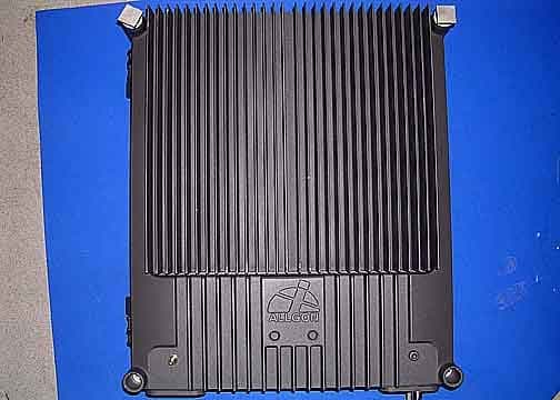
Click to zoom
Application Details
- Equipment Class
- PCB - PCS Licensed Transmitter
- Date of Grant
- Sep 07, 2006
- Application Purpose
- Original Equipment
- Date of Application
- Sep 06, 2006
- Equipment Note
- Fiber-Fed Repeater/Radio Head
- Frequency Range
- 1930.00000000 - 1990.00000000
- Company
- Powerwave Technologies Inc
- Country
- United States
Documents & Files
Document Text
Text extracted from the exhibit documents filed with the FCC. Open a document above to read the original.
Users Manual
Utfärdare/Issued by Product Management Dattum/Date 2006-02-09 Godkänd/Approved SYKLK Dok nr/Doc no RH300000/100-201 Rev A Sida/Page Dok namn/Doc name PRELIMINARY PRODUCT SPECIFICATION Fil/file RH300000_100_A.doc Wide band Radio Head CDMA1900 MHz Product Number: RH300000/100 (incl. Fibre Optical Node) 1. Electrical specification (typical values) Applicable standards: - Radio Transmission and Reception FCC - EMC 3GPP TS25.113 - Environmental ETS 300 019-2-4 Frequency band UL CDMA 1850 – 1910 MHz Frequency band DL CDMA 1930 – 1990 MHz Gain, maximum 35.7 dB Gain adjustment range > 30 dB Gain step resolution 1 dB Gain variation within each relevant band <2 dB Max absolute delay (excluding fibre or coaxial cable delay) <300 ns Noise figure including fiber optic interface at max gain* <5 dB System Fiber optical loss < 10 dB System Fiber optical link length 20 km System input power range +10 to +40 dBm Receiver input port return loss 14 dB Power supply voltage AC 115 - 230 VAC Power supply voltage DC (optional) 21-60 VDC Power consumption max 210 W *Note! If combined with other band, expect lower output power and affected noise figure Output power* dBm/carrier DL 4 carrier 26 8 carrier 23 Input and Output Impedance = 50 Ohms Industry Canada: 20 dB gain bandwidth = 85.6 MHz Utfärdare/Issued by Product Management Dattum/Date 2006-02-09 Godkänd/Approved SYKLK Dok nr/Doc no RH300000/100-201 Rev A Sida/Page Dok namn/Doc name PRELIMINARY PRODUCT SPECIFICATION Fil/file RH300000_100_A.doc 2. Environmental specification Temperature range -13 to + 131 °F -25 to + 55 °C Casing class NEMA4/IP65 3. Mechanical specification Dimensions. (W x H x D) 17.4 x 20.9 x 7.7 Inches 440 x 530 x 195 mm Weight 50 lbs 22.5 Kg RF-connectors N-type female Lock type ABLOY Industry Canada: The Manufacturer's rated output power of this equipment is for single carrier operation. For situations when multiple carrier signals are present, the rating would have to be reduced by 3.5 dB, especially where the output signal is re- radiated and can cause interference to adjacent band users. This power reduction is to be by means of input power or gain reduction and not by an attenuator at the output of the device. FCC CFR 47, Part 15.21 Information to user: Any changes or modifications to the equipment not expressly approved by Powerwave Technologies, Inc. could void The user's authority to operate the equipment. Powerwave Technologies, Inc. will not be responsible for such changes. PowerwaveFiber OpticsPreface VM100 56/EN – User’s ManualRev. P1A9-Draft 2004-11i User’s Manual Fiber Optics – English PrefaceFiber OpticsPowerwave iiRev. P1A9-Draft 2004-11VM100 56/EN – User’s Manual This document contains descriptions of Powerwave fiber optic units. Most sections in the document do not contain comlete information for building, installation, or commissioning systems and are therefore not allowed to be used as any kind of installation or commissioning guide. Only sections specificly declared to be installation or commissioning instructions are allowed to be used for that purpose. Hardware and software mentioned in this document are subjected to continuous development and improvement. Consequently, there may be minor discrepancies between the information in the document and the performance or design of the products. Specifications, dimensions and other statements mentioned in this document are subject to changes without prior notice. Powerwave and its suppliers shall not be liable for any damages related to this product, or for any other damages whatsoever caused of the use of or inability to use any Powerwave product. This is applicable even if Powerwave has been advised of the damage risk. Under any circumstances, Powerwave's entire liability shall be limited to replace such defective software or hardware which was originally purchased from Powerwave. LinDAS is a trademark of Powerwave. Microsoft is a registered trademark of Microsoft Corporation. Windows, Windows 98, Windows NT and Windows 2000 are trademarks of Microsoft Corporation. Intel and Pentium are registered trademarks of Intel Corporation. Hayes is a registered trademark of Hayes Microcomputer Products, Inc. Other trademarks mentioned in this manual are trademarks or registered trademarks of their respective owners. Powerwave Technologies, Inc., 1801 East St. Andrew Place, Santa Ana, CA 92705 USA Phone: +1 714 466 1000 – Fax: +1 714 466 5800 – Internet: www.powerwave.com This manual or parts of it may not be reproduced without the written permission of Powerwave Technologies. Infringements will be prosecuted. All rights reserved. Copyright © Powerwave Technologies, Inc., CA 92705 USA, 1994 – 2004. PowerwaveFiber OpticsPreface VM100 56/EN – User’s ManualRev. P1A9-Draft 2004-11iii Contents Abbreviations .................................................................................................................................. v 1. Safety ......................................................................................................................................... 1-1 Human Exposure of RF Radiation ..................................................................................... 1-3 Repeater Antennas ........................................................................................................ 1-3 Installation and Maintenance of Antenna Systems ....................................................... 1-3 Radiation Exposure ....................................................................................................... 1-4 Radiation Safety Distances ........................................................................................... 1-4 Static Electricity ................................................................................................................. 1-6 2. Introduction ............................................................................................................................... 2-1 Fiber Optics in General ...…
Text truncated - open the document above for the full version.
Users Manual
PowerwaveFiber Optics VM100 56/EN – User’s ManualRev. P1A9-Draft 2004-115 - 1 5.IP Over Fiber IP (Internet Protocol) network is the latest Powerwave network type with UDP/IP protocol and many features, such as wire or fiber connection, PPP, routing capabilities for many sub networks, etc. IP network communication includes communication between network nodes as well as communication between gateway nodes, for instance FON units, and an O&M software. Communication can be initiated either by an O&M software or a network node. When initiated by an O&M software, an operator connects to the network and logs on to the desired node. An OMS station can also initiate scheduled communication that automatically connects to the network and logs on to a node. A network node initiates communication when an alarm is to be transferred, normally to an OMS station. It also initiates communication if callback is required in a logon session. All operation and maintenance of repeaters and remote hubs are carried out via an O&M software connected to a network. There are two network types that can be used for this purpose, IP network and R2R network. This chapter describes IP networks only and is focused on fiber networks. IP networks over wire and R2R networks are described in the VM100 01/EN, OM- Online, User’s Manual. This manual also contains further information about IP networks, IP address planning, and network configuration. This chapter is divided into the following main parts: •Terminology for IP networks, page5-2. •Hardware and software requirements for IP networks, page5-3. •Fiber optic network characteristics, page5-4. •Node units in IP networks, page5-5. •Net interfaces of the FON unit, page5-6. •An example of a network, page5-7. Fiber OpticsPowerwave 5 - 2Rev. P1A9-Draft 2004-11VM100 56/EN – User’s Manual IP Network Terminology In the descriptions of the IP network the terminology in the following table is used. Abbreviations IPInternet Protocol. W-netWire network. F-netFiber network. W-linkWire link. F-linkFiber link. WLIWire Link Interface. FLIFiber Link Interface. Other abbreviations used in this manual are found in the Abbreviations section in the beginning of this manual. Net and Link The following two figures show what a net means and what a link means in this manual. Figure5-1 shows a W-net or F-net with WLI or FLI interface respectively. Figure 5-1. W-net or F-net Figure 5-2 shows a W-link or F-link with WLI or FLI interface respectively. Figure 5-2. W-link or F-link Network typeIP ProtocolIP Network nameW-netF-net Link nameW-linkF-link Link mediaWireFiber Link interfaceWLIFLI FONFONFONFON PowerwaveFiber Optics VM100 56/EN – User’s ManualRev. P1A9-Draft 2004-115 - 3 Requirements To be able to use an IP network, the FON hardware and software stated below is required. Hardware and software that does not meet the requirements below can be upgraded. FON hardware FON boardK129. FON software FONSA102 05/1 version R1A or higher. O&M software versions An OM-Online, OMT32, or OMS station intended to be used on an IP network requires the following software versions: OM-OnlineSA102 60/1 version R1A or higher. OMT32SA102 51/3 version R2A or higher. OMSSA102 54/1 version R2A or higher. Fiber OpticsPowerwave 5 - 4Rev. P1A9-Draft 2004-11VM100 56/EN – User’s Manual F-Net Characteristics The IP communication signal in an F-net is modulated on a sub carrier below the RF modulated signal. The communication transfer rate is 66Kb per second. F-net can be built up with separate downlink and uplink fibers, multi-drop link communication, and a dedicated master node and slave nodes (M and S respectively in the left figure). F-net can also be built up with single fiber and full-duplex transmission, see Figure 5-3. Figure 5-3. Single fiber network with five nodes The network shown in Figure 5-3 has optical WDMs (DXO) in each node, which makes it possible to use one downlink wavelength and four different uplink wavelengths in the same fiber. An F-net contains one master node (the left FON unit in Figure 5-3) and it can contain up to approximately four slave nodes (the right FON units) due to the signal power sharing in the optical splitters. In Figure 5-3 there are three 50/50 percent splitters that reduce the signal power to each of the four slave nodes to 25% of the initial signal power. In Figure 5-3, the master node is a gateway by means of an RCC. It can communicate with an O&M software via modem. The left FON node (CS) only shall be configured with Control Station Capability and thus be the master unit. None of the other FON nodes are allowed to have the Control Station Capability because it is a master/slave network. Only one node is allowed to speak at the same time. Control Station Capability is described in the VM100 01/EN, OM-Online, User’s Manual. FO M S S FONFONFON FONFON RCC 50 50 PSTN BTS 1 DX O DX O FON DX O DX O DX O FON CS 50 50 50 50 FON PowerwaveFiber Optics VM100 56/EN – User’s ManualRev. P1A9-Draft 2004-115 - 5 Node Units This section describes an example of node units used for communication between an O&M software and the nodes in a network. A PC workstation loaded with the O&M software and configured with a modem can be connected to all nodes that have an RCC (or RCU) and communicate with other units in connected W-nets and F-nets. Figure 5-4 shows an O&M workstation connected to an F-net, which is also connected to two W-nets. Figure 5-4. O&M workstation connected to an F/W-net The fibers between the BMU and the FOR units are used for both RF transmission and network communication. An internal backbone W-net in the BMU interconnects the FON units. The two FOR units are also included in two W-nets together with two additional repeaters in each of these W-nets. The O&M workstation in Figure 5-4 can communicate with any of the seven units (one BMU and six repeaters) included in the F-nets and W-nets. RCC BSC/CU BSC/CU RF RF RF RF RF BMU FOR FON FON RF FON RF FON RF RF BSC/CU BSC/CU BSC/CU BSC/CU…
Text truncated - open the document above for the full version.
Cover Letter(s)
CORRESPONDENCE Response to: E06-000193-1 Non-Conformities FCC ID: E675JS0084 (Ref # E06-000193-1) The items listed below represent requests for information following review of this application. Further question may arise pending review of responses to these items. 1 The operational description provided includes very specific detail regarding the equipment, but provides not generic overview of the product. Please provide a brief explaination of the product including a statement of how the device operates in accordance with 2.1033(c)(13). Response: A revised operational description has been uploaded. 2 Since this device contains class A digital circuitry, please provide a label with labeling requirements in accordance with 15.19(a)(1). Response: A revised label has been uploaded. 3 Please provide statement regarding modification to the equipment in accordance with 15.21. Response: A revised users manual has been uploaded. CORRESPONDENCE Response to: E06-000193-2 Non-Conformities FCC ID: E675JS0084 (Ref # E06-000193-2) The items listed below represent requests for information following review of this application. Further question may arise pending review of responses to these items. 1 Please confirm via operational description whether this equipment demodulates the RF signal in the conversion from Fiber to RF. Note: Equipment which demodulates RF signals must be tested as a transmitter. 2 Response: The equipment does NOT modulate or demodulate the incoming signal. The modulation is provided by the signal generator, the fiber optic conversion simply translates the incoming digital information from the fiber back into RF. This allows the RH300000/100 to be placed at a much greater distance from the base station than a standard RF cable would.
External Photos
Front Back Left Right Bottom
ID Label/Location Info
Description AB C D E E D C BA 1 2 345 5 4 3 2 1 This document and its content is th e property of LGPALLGON AB and must not be copied, reproduced, transmitted or disclosed to any third partywithout our consent. Contravention will be prosecuted. This document and its content is th e property of LGPALLGON AB and must not be copied, reproduced, transmitted or disclosed to any third partywithout our consent. Contravention will be prosecuted. Treatment Tolerance accISO 2768-1 Drawn by/Date CAD-file Drawing no. Page Size Rev Scale Finish Note Note Name Material PART No No Pos A4 . . . . . . . . . . . . . . . . Printed label VD203 95/1-201 C 031208 TJn 1:1 M ater i a l Silver coloured metallized polyester Brady B-486 "Mondo Bondo" or similar. The Powerwave logotype is shown in a simplified mode, when printing the label use a correct Note: The label material should be made of UL - recognized material according to category PGJI2 be black. file for the Powerwave logotype.The print colourshould VD201 77/1-201 Data Matrix code VD203 95/1-201VD203 95/1-201 VD203 95/1 FCC ID:MODEL: I C: This device complies with part 15 and, 22 or 24 or 90 of the FCC rules. Operation is subject to the followingtwo conditions:(1)This device may not cause harmful interference,and (2) this device must accept any interferencerecived,including interference that may cause undesired operation. D C B A 1 23 X 1,2,3= Text alternative according to document VD204 60/1 Font S i z e B= ARIAL BOLD 3mmC= ARIAL 1,6mm D= ARIAL 3mm A Serial number
Operational Description
RH300000/100 Wide Band Radio Head Operational Description The RH300000/100 is a 1900 MHz wide band RF repeater intended for use in a wide band coverage system (WCS) for increased coverage in an indoor or outdoor application. It is equipped with a fiber optic converter for optical transmission on the input side and a type N RF output port for a service antenna or RF cable. It also contains an AC to DC power supply unit. The incoming optical signal is converted to RF and amplified for transmission at the output port.
Parts List/Tune Up Info
PowerwaveFiber Optics VM100 56/EN – User’s ManualRev. P1A9-Draft 2004-116 - 1 6.Commissioning Read carefully Chapter1,Safetybefore commissioning the optical system. See also the safety precautions for the current repeater or hub types. Check all connections made during the installation. Also, ensure that both the mains plugs for repeaters equipped with two power supply units are connected to outlets supplied from the same fuse. To fulfill the IP65 weather protective requirements, ensure that the cable strain relief bushings are properly tightened. Also, ensure that the gaskets at the cable inlets on the cabinet are properly fitted and not damaged. When the installation is checked, commission the optical system as described in the following sections: Equipment required for the commissioning is listed below. This chapter contains commissioning instructions only. If you want to read descriptions of the various functions, see the previous chapters in this manual. Some system configuration examples are found on page6-6 and the following pages. If you get problems when commissioning the system, please contact your nearest Powerwave representative. Equipment Required To be able to commissioning an optical system you will need the following: •Optical power meter. •Laptop with O&M software and an RS232 serial cable. •Spectrum analyzer. •Repeater tools. •Optical clenaer. Fiber OpticsPowerwave 6 - 2Rev. P1A9-Draft 2004-11VM100 56/EN – User’s Manual Commissioning the Fiber Optic System Commission the optical transmission system as described in the following instruction. The instruction covers the optical system only and is therefore applicable to all units with optical transmission, for instance BMU, RMU, OCM, FOR, and RH. Figure 6-1 shows a fiber optic system in a BMU and a FOR. These units are also used as examples in the instruction. Figure 6-1. Master unit downlink path Master Unit Downlink Path 1.Make sure the BMU is switched off. 2.Measure the downlink input RF signal power (from the BTS) at the FON board connector ’P101’ in Figure 6-1 (or at the OCM/BMU 19" rack) using a spectrum analyzer. The signal power should be between +10dBm and +36dBm. Write down the measured power value. 3.Switch the BMU on and wait until it is in operational mode. 4.Connect the O&M software to the FON board. 5.Measure the optical output power from the FON board (TX) using an optical power meter. If there is only one slave unit on a short distance, choose the low power range. Otherwise, keep the default high power range. If you are in doubt, choose high power and, if needed, change to low power if the received optical power is more than 4dBm at the slave unit. 6.Set the transmitter attenuation (TX Att.) to a value that gives the following optical transmitter an input power of approximately 0dBm. The attenuation is set via the O&M software (FON configuration). P P101 – 20dB – XdB = 0dBMeassured RF input signal level at P101 minus 20dB minus XdB attenuation equals 0dB. X is the attenuation set via O&M software. Write down the attenuation set. BTS BMU FON DC FON FOR P101 TX Att. 0dBm TX 1 TX RX 1 TXRX D P X UL DL D P X PowerwaveFiber Optics VM100 56/EN – User’s ManualRev. P1A9-Draft 2004-116 - 3 7.Measure the optical output power from the FON board (TX) using an optical power meter. Write down the measured power value. It is recommended to set date and time in the FON units, and to assign names to the units for future tracking. Slave Units Continue by performing the following on each slave unit. 8.Make sure the FOR/slave unit is switched off. 9.If two fibers are used, then make sure the uplink and downlink fibers are connected correctly in the FOR/slave unit. The downlink fiber has to be connected to the RX port and the uplink fiber to the TX port of the FON unit, see Figure 6-2. The FOR in the figure is a compact repeater. Figure 6-2. Fiber connection in a slave unit P 1 0 2 P 1 3 0 B e r y l l i u m o x i d e h a z a r d P 1 0 3 P 1 0 1 P 1 1 4 P 1 0 8 P 1 1 2 P 1 1 1 P 1 0 5 P 1 1 0 P 1 0 9 P 1 1 5 P 1 0 6 P 1 0 4 RX TX P 1 1 3 ANT LO HI PSM FON Fiber optic cables Fiber OpticsPowerwave 6 - 4Rev. P1A9-Draft 2004-11VM100 56/EN – User’s Manual Figure 6-3. Slave unit downlink path, and uplink path 10.Switch the FOR on and wait until it is in operational mode. 11.Connect an O&M software to the FON board. 12.Measure the optical downlink input power (’RX’ in Figure 6-3). The receiver level is measured via the O&M software (FON status). Write down the measured optical power value. 13.Calculate the optical power loss from the TX port of the master FON board (step5) to the RX port of the FOR/slave unit (step12). The loss includes fibers, WDMs, splitters, and connectors used in the current configuration. The calculated optical loss should not exceed 15dB. Write down the calculated optical loss value. 14.Set the receiver attenuation (RX Att.) via the O&M software (FON configuration). An approximate receiver attenuation value can be set according to the calculated loss over the fiber in step13. Choose value from the table. 15.Move the O&M software from the FON board to the repeater and set the desired repeater bandwidth and downlink gain. 16.Move the O&M software back to the FON board and set the transmitter attenuation (TX Att.) to a calculated value that gives the following optical transmitter an input power of approximately 0dBm. 17.Choose optical transmitter output power range via the O&M software as described in step6. FON FOR BMU FON DC RX Att. BTS RX Att.RX TX Att. 0dBm dBm 1 TXRX 1 TXRX UL DL D P X D P X Optical loss over fiberReceiver attenuation 10dB10dB !10dB5dB PowerwaveFiber Optics VM100 56/EN – User’s ManualRev. P1A9-Draft 2004-116 - 5 18.Move the O&M software back to the repeater and set uplink attenuation and gain. Example of downlink and uplink settings are found in the following table. The optical system is now ready for operation. A fine-tuning of the system should be done to get the most out of the system. And…
Text truncated - open the document above for the full version.
Test Report
Page 1 of 93 Report No.: FC06-030A ADDENDUM TO POWERWAVE TECHNOLOGIES, INC. TEST REPORT FC06-030 FOR THE FIBER-FED REPEATER/RADIO HEAD, RH300000/100 FCC PART 24 SUBPART E AND RSS-131 COMPLIANCE DATE OF ISSUE: SEPTEMBER 1, 2006 PREPARED FOR: Powerwave Technologies, Inc. 1801 E. St. Andrew Place Santa Ana, CA 92705 PREPARED BY: Mary Ellen Clayton CKC Laboratories, Inc. 5046 Sierra Pines Drive Mariposa, CA 95338 P.O. No.: 106623 W.O. No.: 85071 Date of test: April 13 – August 30, 2006 Report No.: FC06-030A This report contains a total of 93 pages and may be reproduced in full only. Partial reproduction may only be done with the written consent of CKC Laboratories, Inc. The results in this report apply only to the items tested, as identified herein. Page 2 of 93 Report No.: FC06-030A TABLE OF CONTENTS Administrative Information .............................................................................................3 FCC to Canada Standard Correlation Matrix...................................................................4 Conditions for Compliance ..............................................................................................4 Approvals .........................................................................................................................4 Equipment Under Test (EUT) Description ......................................................................5 Equipment Under Test .....................................................................................................5 Peripheral Devices ...........................................................................................................5 Temperature and Humidity During Testing.....................................................................6 FCC 2.1033(c)(3) User’s Manual ....................................................................................6 FCC 2.1033(c)(4) Type of Emissions ..............................................................................6 FCC 2.1033(c)(5) Frequency Range................................................................................6 FCC 2.1033(c)(6) Operating Power.................................................................................6 FCC 2.1033(c)(7) Maximum Power Rating ....................................................................6 FCC 2.1033(c)(8) DC Voltages .......................................................................................6 FCC 2.1033(c)(9) Tune-Up Procedure ............................................................................6 FCC 2.1033(c)(10) Schematics and Circuitry Description..............................................6 FCC 2.1033(c)(11) Label and Placement ........................................................................6 FCC 2.1033(c)(12) Submittal Photos ..............................................................................6 FCC 2.1033(c)(13) Modulation Information ...................................................................6 FCC 2.1033(c)(14)/2.1046/24.232 - RF Power Output ...................................................7 RSS-131 - RF Power Output............................................................................................10 FCC 2.1033(c)(14)/2.1051/24.238 - Spurious Emissions at Antenna Terminal..............11 FCC 2.1033(c)(14)/2.1053/24.238 - Field Strength of Spurious Radiation ....................12 Blockedge Plots ...............................................................................................................16 Input Plots ........................................................................................................................27 Output Plots .....................................................................................................................43 Intermodulation Plots.......................................................................................................59 RSS-131 99% Bandwidth ................................................................................................65 RSS-131 10 dB Gain Bandwidth .....................................................................................81 RSS-131 Gain ..................................................................................................................83 RSS-131 Gain Linearity...................................................................................................90 Page 3 of 93 Report No.: FC06-030A ADMINISTRATIVE INFORMATION DATE OF TEST: April 13 – August 30, 2006 DATE OF RECEIPT: April 13, 2006 FREQUENCY RANGE TESTED: 9 kHz-20 GHz MANUFACTURER: Powerwave Technologies, Inc. 1801 E. St. Andrew Place Santa Ana, CA 92705 REPRESENTATIVE: Jeffrey Dale TEST LOCATION: CKC Laboratories, Inc. 110 Olinda Place Brea, CA 92823 TEST METHOD: FCC Part 24, RSS-131 and RSS-GEN PURPOSE OF TEST: To demonstrate the compliance of the Fiber-Fed Repeater/Radio Head, RH300000/100 with the requirements for FCC Part 24 and RSS-131 devices. Addendum A adds RF power and gain linearity for RSS-131 with new testing. Page 4 of 93 Report No.: FC06-030A FCC TO CANADA STANDARD CORRELATION MATRIX Canadian Standard Canadian Section FCC Standard FCC Section Test Description RSS 1315.4N/AN/AExternal Controls RSS 1315.547 CFR1.1307RF Exposure RSS 1316.1N/AN/APassband Gain and Bandwidth RSS 1316.247 CFR24.232RF Power Output RSS 1316.3TIA/EIA603Non-Linearity (Intermodulation Attenuation) RSS 1316.447 CFR24.238Spurious Emissions Limitations RSS 1316.5N/AN/AFrequency Stability (Band Translators) IC 3172-A90473Site File No. CONDITIONS FOR COMPLIANCE No modifications to the EUT were necessary to comply. APPROVALS Steve Behm, Director of Engineering Services QUALITY ASSURANCE:TEST PERSONNEL: Joyce Walker, Quality Assurance Administrative Manager Eddie Wong, EMC Engineer Page 5 of 93 Report No.: FC06-030A EQUIPMENT UNDER TEST (EUT) DESCRIPTION The customer declares the EUT tested by CKC Laboratories was representative of a production unit. EQUIPMEN…
Text truncated - open the document above for the full version.
Test Report
DC Voltages –85071 14VDC, 4A into the output devices
Test Setup Photos
RF Output Power Direct Connect Radiated Emissions - Front View Radiated Emissions - Back View RSS-131 Gain
Contact Information
Applicant
Jeff Dale(Principal Reliability Engineer)
Technical Contact
CKC Laboratories, Inc.Mary Ellen Clayton
[email protected]209-966-5240
5046 Sierra Pines Drive · Mariposa, California · United States
Non-Technical Contact
CKC Laboratories, Inc.Mary Ellen Clayton
[email protected]209-966-5240
Test Firm
CKC Laboratories, Inc.Steve Behm
Technical Specifications
| # | Rule Parts | Frequency Range | Power Output | Emission | Tolerance |
|---|---|---|---|---|---|
| 4 | 24E | 1.93 GHz - 1.99 GHz | 1 W | G7W | Amp |
Other Applications from Powerwave Technologies Inc

E675JS0123
Nov 03, 2011Multi-carrier RF Power Amplifier
Equipment Class
AMP - Amplifier
E675JS0120
Aug 26, 2010Nexus Dual Band Repeater
Equipment Class
TNB - Licensed Non-Broadcast Station Transmitter
E675JS0119
Aug 01, 2010Nexus Dual Band Repeater
Equipment Class
PCB - PCS Licensed Transmitter
E675JS0118
Jul 26, 2010Nexus Dual Band Repeater
Equipment Class
PCB - PCS Licensed Transmitter
E675JS0096
Jan 10, 2008Wideband Radio Head
Equipment Class
TNB - Licensed Non-Broadcast Station Transmitter