E675JS0088Multi-carrier RF Power Amplifier
Powerwave Technologies Inc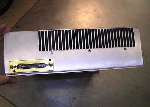
Click to zoom
Application Details
- Equipment Class
- AMP - Amplifier
- Date of Grant
- Aug 01, 2006
- Application Purpose
- Original Equipment
- Date of Application
- Aug 01, 2006
- Equipment Note
- Multi-carrier RF Power Amplifier
- Frequency Range
- 1930.00000000 - 1990.00000000
- Company
- Powerwave Technologies Inc
- Country
- United States
Documents & Files
Document Text
Text extracted from the exhibit documents filed with the FCC. Open a document above to read the original.
Users Manual
G3L-1929-160 Installation and Service Manual 044-05237 Rev A June 2006 Multi-Carrier Power Amplifier © 2006 Powerwave Technologies Incorporated. All rights reserved. Powerwave Technologies, and the Powerwave logo are registered trademarks. This Powerwave product is intended only for installation in a RESTRICTED ACCESS LOCATION and this Powerwave product is designed to operate within the normal operating (typical operating) ranges or conditions specified in this document. Operation of this equipment beyond the specified ranges in this document may cause: 1. Spurious emissions that violate regulatory requirements. 2. The equipment to be automatically removed from service when maximum thresholds are exceeded. 3. The equipment to not perform in accordance with its specifications. It is the operator’s responsibility of the operator to ensure this equipment is properly installed and operated within Powerwave operating specifications to obtain proper performance from the equipment and to comply with regulatory requirements. For PERMANENTLY CONNECTED EQUIPMENT, a readily accessible disconnect device shall be incorporated in the building permanent wiring. 044-05237 Rev Ai Warnings, Cautions, and Notes Warnings, Cautions, and Notes are found throughout this manual where applicable. The associated icons are used to quickly identify a potential condition that could result in the consequences described below if precautions are not taken. Notes clarify and provide additional information to assist the user. WARNING: This warning symbol means danger. You are in a situation that could cause bodily injury or death. Before working on any equipment, be aware of the hazards involved with electrical and RF circuits and be familiar with standard practices for preventing acci- dents. CAUTION: The caution symbol means reader be careful. In this situation, the user might do something that could result in equipment damage or loss of data. NOTE The note symbol means reader take note. Notes contain helpful suggestions or references to material not covered in this document. Procedures are not contained in notes. ii044-05237 Rev A Revision Record Revision Letter Date of ChangeReason for Change AJune 2006Initial Release 044-05237 Rev Aiii Table of Contents Chapter 1 - Product Description 1.1 Introduction . . . . . . . . . . . . . . . . . . . . . . . . . . . . . . . . . . . . . . . . . . . . . . . . . . . . . . . . . . . . . . . . . . . . .1-1 1.2 Scope of Manual. . . . . . . . . . . . . . . . . . . . . . . . . . . . . . . . . . . . . . . . . . . . . . . . . . . . . . . . . . . . . . . . .1-1 1.3 Product Description . . . . . . . . . . . . . . . . . . . . . . . . . . . . . . . . . . . . . . . . . . . . . . . . . . . . . . . . . . . . . .1-1 1.4 Functional Description . . . . . . . . . . . . . . . . . . . . . . . . . . . . . . . . . . . . . . . . . . . . . . . . . . . . . . . . . . . .1-1 1.4.1 Preamplifier . . . . . . . . . . . . . . . . . . . . . . . . . . . . . . . . . . . . . . . . . . . . . . . . . . . . . . . . . . . . . . . . . . .1-3 1.4.2 Main and Error Amplifiers . . . . . . . . . . . . . . . . . . . . . . . . . . . . . . . . . . . . . . . . . . . . . . . . . . . . . . . .1-3 1.4.3 Feed-forward Loop Control Circuits. . . . . . . . . . . . . . . . . . . . . . . . . . . . . . . . . . . . . . . . . . . . . . . . .1-4 1.4.4 Pilot Tone Generator . . . . . . . . . . . . . . . . . . . . . . . . . . . . . . . . . . . . . . . . . . . . . . . . . . . . . . . . . . . .1-4 1.4.5 Controller . . . . . . . . . . . . . . . . . . . . . . . . . . . . . . . . . . . . . . . . . . . . . . . . . . . . . . . . . . . . . . . . . . . . .1-4 1.5 Cooling . . . . . . . . . . . . . . . . . . . . . . . . . . . . . . . . . . . . . . . . . . . . . . . . . . . . . . . . . . . . . . . . . . . . . . . .1-4 1.6 Power Distribution . . . . . . . . . . . . . . . . . . . . . . . . . . . . . . . . . . . . . . . . . . . . . . . . . . . . . . . . . . . . . . .1-5 Chapter 2 - Controls and Indicators 2.1 Introduction . . . . . . . . . . . . . . . . . . . . . . . . . . . . . . . . . . . . . . . . . . . . . . . . . . . . . . . . . . . . . . . . . . . . .2-1 2.2 MCPA Controls and Indicators . . . . . . . . . . . . . . . . . . . . . . . . . . . . . . . . . . . . . . . . . . . . . . . . . . . . . .2-1 2.2.1 MCPA Alarms . . . . . . . . . . . . . . . . . . . . . . . . . . . . . . . . . . . . . . . . . . . . . . . . . . . . . . . . . . . . . . . . .2-1 2.2.2 MCPA Connectors . . . . . . . . . . . . . . . . . . . . . . . . . . . . . . . . . . . . . . . . . . . . . . . . . . . . . . . . . . . . . .2-3 Chapter 3 - Installation 3.1 Introduction . . . . . . . . . . . . . . . . . . . . . . . . . . . . . . . . . . . . . . . . . . . . . . . . . . . . . . . . . . . . . . . . . . . . .3-1 3.2 Unpacking and Inspection . . . . . . . . . . . . . . . . . . . . . . . . . . . . . . . . . . . . . . . . . . . . . . . . . . . . . . . . .3-1 3.2.1 Damaged Equipment . . . . . . . . . . . . . . . . . . . . . . . . . . . . . . . . . . . . . . . . . . . . . . . . . . . . . . . . . . . .3-1 3.3 Air Conditioning Requirement. . . . . . . . . . . . . . . . . . . . . . . . . . . . . . . . . . . . . . . . . . . . . . . . . . . . . . .3-1 3.4 MCPA Installation Instructions . . . . . . . . . . . . . . . . . . . . . . . . . . . . . . . . . . . . . . . . . . . . . . . . . . . . . .3-1 3.5 Initial Start-up and Operating Procedures . . . . . . . . . . . . . . . . . . . . . . . . . . . . . . . . . . . . . . . . . . . . .3-3 Chapter 4 - Maintenance 4.1 Introduction . . . . . . . . . . . . . . . . . . . . . . . . . . . . . . . . . . . . . . . . . . . . . . . . . . . . . . . . . . . . . . . . . . . . .4-1 4.2 Periodic Maintenance . . . . . . . . . . . . . . . . . . . . . . . . . . . . . . . . . . . . . . . . . . . . . . . . . . . . . . . . . . . . .4-1 4.3 MCPA Performance Tests . . . . . . . . . . . . . . . . . . . . . . . . . . . . . . . . . . . . . . . . . . . . . . . . . . . . . . . . .4-1 4.4 Troub…
Text truncated - open the document above for the full version.
External Photos
Front Back Top Bottom Side 1 Side 2
ID Label/Location Info
Functional DescriptionG3L-1929-160 MCPA 1-2044-05237 Rev A Figure 1-1 MCPA Front and Rear Views Front Rear
Operational Description
044-05237 Rev A1-1 Chapter 1 Product Description 1.1Introduction This manual contains information and procedures for the installation, operation, and maintenance of the G3L-1929-160 Multi-Carrier Power Amplifier (MCPA). 1.2Scope of Manual This manual is intended for use by service technicians familiar with similar types of equipment. It contains service information required for the equipment described and is current as of the printing date. Changes which occur after the printing date may be incorporated by a complete manual revision or alternatively as additions. The manual is organized into the following chapters: 1.3Product Description The MCPA shown in Figure 1-1 is a linear, feed-forward multi-carrier power amplifier that operates in a 60 MHz frequency band from 1930 MHz to 1990 MHz with an instantaneous bandwidth of 40 MHz. The instantaneous bandwidth is the maximum frequency band in which any two or more signals can occupy. The instantaneous bandwidth of the MCPA is set automatically. The MCPA is modular in design and ideally suited for use in GSM, EDGE, CDMA, and W-CDMA base stations. The MCPA provides a gain of 63 dB to supply a 160 watt output. Refer to Figure 1-2 for the MCPA functional block diagram. Refer to Chapter 5 for the MCPA specifications. 1.4Functional Description The MCPA is a self-contained module typically operated in parallel with other identical MCPAs as part of a subrack assembly. The MCPA consists of the following major functions: • Preamplifier • Main and error amplifiers • Feed-forward loop control circuits • Pilot tone generator • Controller Chapter 1 - Product Description Chapter 2 - Controls and Indicators Chapter 3 - Installation Chapter 4 - Maintenance Chapter 5 - Specifications Functional DescriptionG3L-1929-160 MCPA 1-2044-05237 Rev A Figure 1-1 MCPA Front and Rear Views Front Rear G3L-1929-160 MCPAFunctional Description 044-05237 Rev A1-3 1.4.1 Preamplifier The carrier (RF In) is applied to the input port of the MCPA and fed to the preamplifier stage where it is amplified using two stages of class A mode amplifiers. The output of the preamplifier is split into two paths, one to the main amplifier and one to the error amplifier. 1.4.2 Main and Error Amplifiers The main amplifier provides the balance of gain and power in the 1930 MHz to 1990 MHz frequency band, using class AB amplification for maximum efficiency. The error amplifier and feed forward loops correct signal non-linearities introduced by the class AB main amplifier. In the error amplifier, which operates in class A mode, the RF signal is coupled to an attenuator and phase shifter in the first feed-forward loop, phase shifted by 180 degrees and then amplified in the premain amplifier. The output from the pre-main amplifier is fed to the class AB main amplifier and then sampled using a coupler. The signal (RF sample) is combined with the main input signal and input to the second feed-forward loop. There, the RF sample is attenuated, phase shifted 180 degrees, and fed to the error amplifier where it is amplified to a level identical to the sample output from the main amplifier. The output from the error amplifier (Error Out) is coupled back and added to the output from the main amplifier, with the control loops continuously making adjustments to cancel out any distortion in the final output signals. Preamp Delay Second Loop Phase and Gain Error Amplifier First Loop Phase and Gain Reflected Power (VSWR) RF Out Pilot Tone Generator RF Sample Forward Power / Pilot Tone Detect RF In Premain Amplifier Error Out Delay Filter Main Amplifier System Faults Front Panel LED Status ON/OFF/RESET Switch Control VDCVDC VDCVDC +27 VDC User Interface Pilot Tone Controller First Loop Detection FIRST LOOP SECOND LOOP First Loop Control Second Loop Control -5 +5+9+15 Figure 1-2 MCPA Functional Block Diagram CoolingG3L-1929-160 MCPA 1-4044-05237 Rev A 1.4.3 Feed-forward Loop Control Circuits The primary function of the first loop is to amplify the carrier signals and isolate an error signal for the second loop. It does this by amplifying the carrier signals and isolating an error signal which is passed to the second loop. The first loop control section phase shifts the main input signals by 180 degrees and constantly monitors the output for correct phase and gain. The primary function of the second loop is to amplify the error signal to cancel out spurious products developed in the main amplifier. The input signal is amplified by a preamplifier and fed to a coupler and delay line. The signal from the coupler is fed to the attenuator and phase shifter in the first loop. The second loop control section obtains a sample of the distortion added to the output signals by the main amplifiers. The signal is phase shifted 180 degrees, then fed to the error amplifier where it is amplified to the same power level as the input sample. The signal is then coupled to the main amplifier output. The final output is monitored by the second loop and adjusted to ensure that the signal distortion and intermodulation distortion on the final output is cancelled out. During routine operation, all normal variations are automatically compensated for by the feed-forward loop control. If large variations occur beyond the adjustment range of the loop control, the controller shuts down the MCPA RF section and a loop fault is reported to the system. 1.4.4 Pilot Tone Generator The pilot tone is an internally generated signal with a predetermined frequency, phase, and amplitude is known. If the pilot signal is suppressed at the amplifier output, then the distortion created by the main amplifier is also suppressed. The pilot tone signal is injected into the first loop and detected at the feedforward output of the second loop. The pilot tone is coupled off of the main amplifier creating a second pilot tone that is attenuated and phase shifted 180 degrees to be used as the reference. The second pilot tone is amplified in the error amplifier and mixed…
Text truncated - open the document above for the full version.
Operational Description
DC Voltages – 85227 27VDC, 3A into the output devices
Parts List/Tune Up Info
044-05237 Rev A4-1 Chapter 4 Maintenance 4.1Introduction This chapter contains instructions for periodic maintenance, testing and troubleshooting for the G3L- 1929-160 Multi-Carrier Power Amplifier (MCPA). 4.2Periodic Maintenance Periodic maintenance requirements for the MCPA are listed in Table 4-1. 4.3MCPA Performance Tests MCPA Performance tests are only performed at the factory. Refer to the troubleshooting instructions in Section 4.4. 4.4Troubleshooting Perform the instructions in Table 4-2 in the case of an MCPA fault or alarm. 4.5MCPA Removal and Replacement Perform the instructions in Table 4-3 to remove and replace a MCPA. NOTE Check your sales order and equipment warranty before attempting to service or repair unit. Do not break seals on equipment under warranty or warranty will be null and void. Do not return equipment for warranty or repair service until proper shipping instructions are received from factory. Table 4-1 Recommended Periodic Maintenance TaskIntervalAction Cleaning 3 MonthsInspect for debris especially around front panel vents. Remove dust with a soft cloth/brush or vacuum cleaner Performance testsOptionalPerform testing in accordance with Paragraph 4.3. Table 4-2 Troubleshooting StepAction 1Check for proper DC supply voltage. 2Set the OFF/ON/RESET switch momentarily to RESET (Up) position. 3Contact your field representative or the factory if fault does not clear. Return For Service ProceduresG3L-1929-160 MCPA 4-2044-05237 Rev A 4.6Return For Service Procedures When returning products to Powerwave, the following procedures will ensure optimum response. 4.6.1 Obtaining An RMA A Return Material Authorization (RMA) number must be obtained prior to returning equipment and to reduce delays in receiving repair service. Please contact our Repair Department at (714) 466-1000 to obtain this number, or FAX your request to (714) 466-5816. 4.6.2 Repackaging for Shipment To ensure safe shipment of a component, it is recommended that the original packing materials be reused If this is not possible, use suitable shipping cartons and foam inserts to prevent damage in transit. CAUTION: Do not slam the MCPA into the system during installation. Using excessive force can damage the MCPA connector. CAUTION: When removing the MCPA from the system, support the MCPA to prevent the rear of the MCPA from suddenly dropping when the guide rail disengages from the track. Dropping the MCPA can damage the rear multi-pin connector. The MCPA weighs approximately 28.60 lbs. (12.97 kg). Table 4-3 MCPA Removal and Replacement StepAction 1Set MCPA OFF/ON/RESET switch to OFF (down). 2Loosen two quarter-turn fasteners that secure MCPA to the subrack. 3With steady even pressure, use handle on front of the MCPA to pull the MCPA out of the system. 4To replace MCPA, set MCPA OFF/ON/RESET switch to OFF (down). 5Turn quarter-turn fasteners to Unlocked position. 6Insert MCPA into subrack. Turn quarter-turn fasteners to locked position to secure MCPA.
Test Report
Page 1 of 95 Report No.: FC06-033A ADDENDUM TO POWERWAVE TECHNOLOGIES, INC. TEST REPORT FC06-033 FOR THE MULTI-CARRIER RF POWER AMPLIFIER, G3L-1929-160 (EVEREST 1900) FCC PART 24 & RSS-131 COMPLIANCE DATE OF ISSUE: JULY 25, 2006 PREPARED FOR: Powerwave Technologies, Inc. 1801 E. St. Andrew Place Santa Ana, CA 92705 PREPARED BY: Mary Ellen Clayton CKC Laboratories, Inc. 5046 Sierra Pines Drive Mariposa, CA 95338 P.O. No.: 107080 W.O. No.: 85227 Date of test: May 31 – July 24, 2006 Report No.: FC06-033A This report contains a total of 95 pages and may be reproduced in full only. Partial reproduction may only be done with the written consent of CKC Laboratories, Inc. The results in this report apply only to the items tested, as identified herein. Page 2 of 95 Report No.: FC06-033A TABLE OF CONTENTS Administrative Information .............................................................................................3 FCC to Canada Standard Correlation Matrix...................................................................4 Conditions for Compliance ..............................................................................................4 Approvals .........................................................................................................................4 Equipment Under Test (EUT) Description ......................................................................5 Equipment Under Test .....................................................................................................5 Peripheral Devices ...........................................................................................................5 Temperature and Humidity During Testing.....................................................................6 FCC 2.1033(c)(3) User’s Manual ....................................................................................6 FCC 2.1033(c)(4) Type of Emissions ..............................................................................6 FCC 2.1033(c)(5) Frequency Range................................................................................6 FCC 2.1033(c)(6) Operating Power.................................................................................6 FCC 2.1033(c)(7) Maximum Power Rating ....................................................................6 FCC 2.1033(c)(8) DC Voltages .......................................................................................6 FCC 2.1033(c)(9) Tune-Up Procedure ............................................................................6 FCC 2.1033(c)(10) Schematics and Circuitry Description..............................................6 FCC 2.1033(c)(11) Label and Placement ........................................................................6 FCC 2.1033(c)(12) Submittal Photos ..............................................................................6 FCC 2.1033(c)(13) Modulation Information ...................................................................6 FCC 2.1033(c)(14)/2.1046/24.232(a) - RF Power Output...............................................7 RSS-131 - RF Power Output............................................................................................10 FCC 2.1033(c)(14)/2.1047(b) - Audio Frequency Response...........................................11 FCC 2.1033(c)(14)/2.1047(b) - Modulation Limiting Response.....................................11 Blockedge ........................................................................................................................11 Input Plots ........................................................................................................................22 Output Plots .....................................................................................................................38 Intermodulation................................................................................................................54 FCC 2.1033(c)(14)/2.1051/24.238(a) - Spurious Emissions at Antenna Terminal .........65 FCC 2.1033(c)(14)/2.1053/24.238(a) - Field Strength of Spurious Radiation ...............70 RSS-131 - 99% Bandwidth ..............................................................................................74 RSS-131 - Gain Linearity ................................................................................................90 Page 3 of 95 Report No.: FC06-033A ADMINISTRATIVE INFORMATION DATE OF TEST: May 31 – July 24, 2006 DATE OF RECEIPT: May 31, 2006 FREQUENCY RANGE TESTED: 9kHz-20GHz MANUFACTURER: Powerwave Technologies, Inc. 1801 E. St. Andrew Place Santa Ana, CA 92705 REPRESENTATIVE: Jeffrey Dale TEST LOCATION: CKC Laboratories, Inc. 110 Olinda Place Brea, CA 92823 TEST METHOD: FCC Part 24 & RSS-131 PURPOSE OF TEST: To demonstrate the compliance of the Multi-Carrier RF Power Amplifier, G3L-1929-160 (Everest 1900) with the requirements for FCC Part 24 & RSS-131 devices. Addendum A adds RF power for RSS-131 with new testing. Page 4 of 95 Report No.: FC06-033A FCC TO CANADA STANDARD CORRELATION MATRIX Canadian Standard Canadian Section FCC Standard FCC Section Test Description RSS 1315.4N/AN/AExternal Controls RSS 1315.547 CFR1.1307RF Exposure RSS 1316.1N/AN/APassband Gain and Bandwidth RSS 1316.247 CFR24.232RF Power Output RSS 1316.3TIA/EIA603Non-Linearity (Intermodulation Attenuation) RSS 1316.447 CFR24.238Spurious Emissions Limitations RSS 1316.5N/AN/AFrequency Stability (Band Translators) 3172-A90473Site File No. CONDITIONS FOR COMPLIANCE No modifications to the EUT were necessary to comply. APPROVALS Steve Behm, Director of Engineering Services QUALITY ASSURANCE:TEST PERSONNEL: Joyce Walker, Quality Assurance Administrative Manager Septimiu Apahidean, EMC Test Engineer Eddie Wong, EMC Engineer Page 5 of 95 Report No.: FC06-033A EQUIPMENT UNDER TEST (EUT) DESCRIPTION The customer declares the EUT tested by CKC Laboratories was representative of a production unit. EQUIPMENT UNDER TEST Multi-Carrier RF Power A…
Text truncated - open the document above for the full version.
Test Setup Photos
PHOTOGRAPH SHOWING RF POWER OUTPUT PHOTOGRAPH SHOWING DIRECT CONNECT TEST SETUP PHOTOGRAPH SHOWING RADIATED EMISSIONS Radiated Emissions - Front View PHOTOGRAPH SHOWING RADIATED EMISSIONS Radiated Emissions - Back View PHOTOGRAPH SHOWING GAIN LINEARITY
Contact Information
Applicant
Jeff Dale(Principal Reliability Engineer)
Technical Contact
CKC Laboratories, Inc.Mary Ellen Clayton
[email protected]209-966-5240
5046 Sierra Pines Drive · Mariposa, California · United States
Non-Technical Contact
CKC Laboratories, Inc.Mary Ellen Clayton
[email protected]209-966-5240
Test Firm
CKC Laboratories, Inc.Steve Behm
Technical Specifications
| # | Rule Parts | Frequency Range | Power Output | Emission | Tolerance |
|---|---|---|---|---|---|
| 4 | 24E | 1.93 GHz - 1.99 GHz | 185 W | G7W | Amp |
Other Applications from Powerwave Technologies Inc

E675JS0123
Nov 03, 2011Multi-carrier RF Power Amplifier
Equipment Class
AMP - Amplifier
E675JS0120
Aug 26, 2010Nexus Dual Band Repeater
Equipment Class
TNB - Licensed Non-Broadcast Station Transmitter
E675JS0119
Aug 01, 2010Nexus Dual Band Repeater
Equipment Class
PCB - PCS Licensed Transmitter
E675JS0118
Jul 26, 2010Nexus Dual Band Repeater
Equipment Class
PCB - PCS Licensed Transmitter
E675JS0096
Jan 10, 2008Wideband Radio Head
Equipment Class
TNB - Licensed Non-Broadcast Station Transmitter