E675JS0090Wideband Radio Head (WRH)
Powerwave Technologies Inc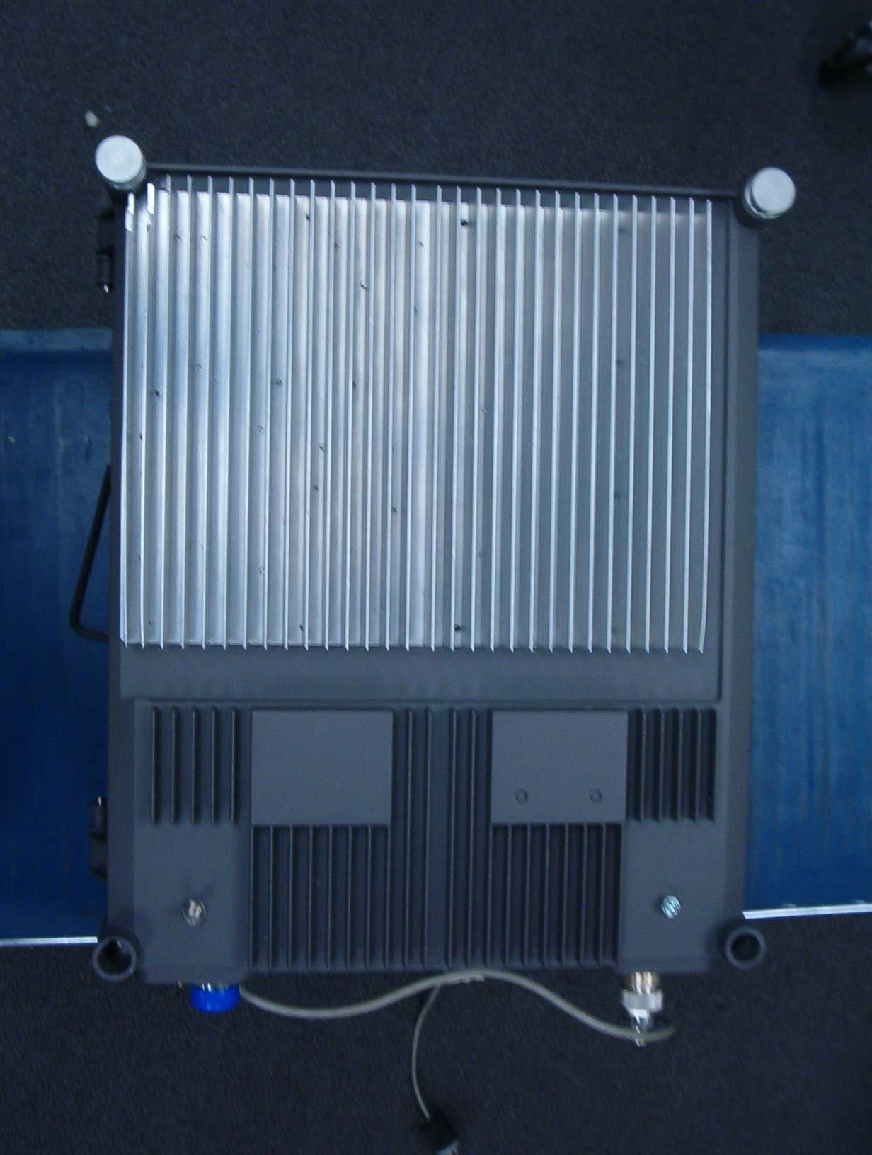
Click to zoom
Application Details
- Equipment Class
- PCB - PCS Licensed Transmitter
- Date of Grant
- Mar 25, 2007
- Application Purpose
- Original Equipment
- Date of Application
- Mar 25, 2007
- Equipment Note
- Wideband Radio Head (WRH)
- Frequency Range
- 1930.00000000 - 1990.00000000
- Company
- Powerwave Technologies Inc
- Country
- United States
Documents & Files
Document Text
Text extracted from the exhibit documents filed with the FCC. Open a document above to read the original.
Users Manual
Installation and Service Manual 044-05251 Rev A February 2007 Wideband Radio Head © 2007 Powerwave Technologies Incorporated. All rights reserved. Powerwave Technologies and the Powerwave logo are registered trademarks. Powerwave Technologies Inc. reserves the right to make changes to the documentation and equipment, includ- ing but not limited to component substitution and circuitry changes. Changes that impact this document may subsequently be incorporated in a later revision of this document. This Powerwave product is designed to operate within the Normal Operating (typical operating) ranges or con- ditions specified in this document. Operation of this equipment beyond the specified ranges in this document may cause (1) spurious emissions that violate regulatory requirements; (2) the equipment to be automatically removed from service when maximum thresholds are exceeded; or (3) the equipment to not perform in accor- dance with its specifications. It is the Operator's responsibility to ensure this equipment is properly installed and operated within Powerwave operating specifications to obtain proper performance from the equipment and to comply with regulatory requirements. The rated output power of this equipment is for single carrier operation. For situations when multiple carrier sig- nals are present, the rating would have to be reduced by 3.5 dB, especially where the output signal is re-radi- ated and can cause interference to adjacent band users. This power reduction is to be by means of input power or gain reduction and not by an attenuator at the output of the device. Input power is rated at 115/230VAC, 50/ 60Hz, and should be protected with a 20 A breaker. Power strips should, at a minimum, conform to this require- ment to prevent equipment damage and possible overload. Federal Communications Commission (FCC) This equipment has been tested and found to comply with the limits for a Class A digital device, pursuant to part 15 of the FCC Rules. Changes or modifications not expressly approved by Powerwave Technologies, Inc. for compliance could void the user’s authority to operate this equipment. These limits are designed to provide reasonable protection against harmful interference when the equipment is operated in a commercial environ- ment. This equipment generates, uses, and can radiate radio frequency energy and, if not installed and used in accordance with the instruction manual, may cause harmful interference to radio communications. Operation of this equipment in a residential area is likely to cause harmful interference in which case the user will be required to correct the interference at his own expense. Industry Canadian Requirement All Powerwave apparatus introduced on the Canadian market meet all requirements of the Canadian Interfer- ence-Causing Equipment Regulations. The -20dB bandwidth is 80MHz. Powerwave Technologies Inc., 1801 East St. Andrew Place, CA 92705 Santa Ana, USA. Phone +1 714 466 1000 – Fax +1 714 466 5800 – Internet www.powerwave.com Wideband Radio HeadRevision Record 044-05251 Rev Ai Revision Record Revision Letter Date of ChangeReason for Change 3AAugust 2005Original VD203 66 ADecember 2006Document number changed to 044-05251 and manual updated ii044-05251 Rev A This Page Intentionally Left Blank 044-05251 Rev Ai Table of Contents Abbreviations . . . . . . . . . . . . . . . . . . . . . . . . . . . . . . . . . . . . . . . . . . . . . . . . . . . . . . . . . . . . . . . . . . . . . . . v Chapter 1 - Product Description Introduction . . . . . . . . . . . . . . . . . . . . . . . . . . . . . . . . . . . . . . . . . . . . . . . . . . . . . . . . . . . . . . . . . . . . . . . .1-1 Scope of Manual . . . . . . . . . . . . . . . . . . . . . . . . . . . . . . . . . . . . . . . . . . . . . . . . . . . . . . . . . . . . . . . . . . . .1-1 Safety . . . . . . . . . . . . . . . . . . . . . . . . . . . . . . . . . . . . . . . . . . . . . . . . . . . . . . . . . . . . . . . . . . . . . . . . . . . .1-1 Warning Signs . . . . . . . . . . . . . . . . . . . . . . . . . . . . . . . . . . . . . . . . . . . . . . . . . . . . . . . . . . . . . . . . . .1-2 Human Exposure of RF Radiation . . . . . . . . . . . . . . . . . . . . . . . . . . . . . . . . . . . . . . . . . . . . . . . . . . .1-2 Antennas . . . . . . . . . . . . . . . . . . . . . . . . . . . . . . . . . . . . . . . . . . . . . . . . . . . . . . . . . . . . . . . . . . .1-2 Installation and Maintenance of Antenna Systems. . . . . . . . . . . . . . . . . . . . . . . . . . . . . . . . . . . .1-2 Radiation Exposure . . . . . . . . . . . . . . . . . . . . . . . . . . . . . . . . . . . . . . . . . . . . . . . . . . . . . . . . . . .1-2 Radiation Safety Distances . . . . . . . . . . . . . . . . . . . . . . . . . . . . . . . . . . . . . . . . . . . . . . . . . . . . . . . .1-3 Electrostatic Discharge (ESD) . . . . . . . . . . . . . . . . . . . . . . . . . . . . . . . . . . . . . . . . . . . . . . . . . . . . . .1-4 Overview . . . . . . . . . . . . . . . . . . . . . . . . . . . . . . . . . . . . . . . . . . . . . . . . . . . . . . . . . . . . . . . . . . . . . . . . . .1-5 WRH . . . . . . . . . . . . . . . . . . . . . . . . . . . . . . . . . . . . . . . . . . . . . . . . . . . . . . . . . . . . . . . . . . . . . . . . . .1-5 WRH-V . . . . . . . . . . . . . . . . . . . . . . . . . . . . . . . . . . . . . . . . . . . . . . . . . . . . . . . . . . . . . . . . . . . . . . . .1-6 Chassis Design . . . . . . . . . . . . . . . . . . . . . . . . . . . . . . . . . . . . . . . . . . . . . . . . . . . . . . . . . . . . . . . . . .1-6 Sub Unit Overview . . . . . . . . . . . . . . . . . . . . . . . . . . . . . . . . . . . . . . . . . . . . . . . . . . . . . . . . . . . . . . .1-6 Wideband Amplifier PCBA (WBA) . . . . . . . . . . . . . . . . . . . . . . . . . . . . . . . . . . . . . . . . . . . . . . . .1-6 Power Amplifier PCBA (PA) . . . . . . . . . . . . . . . . . . . . . . . . . . . . . . . . . . . . . . . . . . . . . . . . . . . . .1…
Text truncated - open the document above for the full version.
Cover Letter(s)
Non-Conformities FCC ID: E675JS0090 (CKC CS Ref # E07-000009-01) The items listed below represent requests for information following review of this application for certification under United S tates (FCC) regulations. . Further question may arise pending review of responses to these items. OK # Non-Conformity or Co mment Submitted Response Respondent / Date of Response X 1 The internal photos exhibit type has been requested to be held confidential. This exhibit type cannot be held conf idential without proper justification. Please update the letter of confidentiality appropriately. Updated letter provided CKC Labs 3/23/07 X 2 The ID Label information clearly shows label loctaion, which is inconsistent with FCC requirements. The ID label must be visible from the exterior of the product. Updated label placement provided CKC Labs 3/23/07 X 3 Please provide an ID label sample photograph or drawing (additional to the label location information) which includes the necessary requirements of 15.19. Updated labels provided. CKC Labs 3/23/07 X 4 Please provide detailed internal photos. Updated photos provided. CKC Labs 3/23/07 X 5 Please provide an updated users manua l incorporating the statement required by 15.21. Updated manual provided. CKC Labs 3/23/07 X 6 Does the fiber to RF translation demodulate the RF signal? “The minimum output RF energy for the TX or DL path is zero RF signal.” CKC Labs 3/23/07 X 7 What is the minimum RF output rating? 0 Watts RF output power. CKC Labs 3/23/07 X 8 NOTE: Tune up procedure and operational description exhibit types have not been requested for confidentiality. If these items require confidentiality, please update the confidentiality request. No respose necessary to this item. None. X 9 Please eplain failing data on page 14 of test report. Updated test report provided – Previous data noted carrier levels CKC Labs 3/26/07
Cover Letter(s)
1801 E. St. Andrew Place, Santa Ana, CA 92705 USA www.powerwave.com +1.714.466.1000 Fax. +1.714.466.5800 Friday, March 09, 2007 Federal Communications Commission Authorization and Evaluation Division 7435 Oakland Mills Road Columbia, MD 21046 Re: Request for Confidentiality In reference to the application under FCC ID: E675JS0090, and pursuant to Sections 0.457(d)(1)(ii) and 0.459 of the Commission's Rules, the Applicant hereby requests confidential treatment of the accompanying information as outlined below: Schematic Diagrams, Internal Photographs. The above materials contain trade secrets and proprietary information not customarily released to the public. The internal circuitry design uses proprietary techniques that are not known by the general public / industry. Powerwave Technologies customers have signed non-disclosure agreements. This product is only serviceable by Powerwave Technologies or a licensee. It is definitely not accessible by the general public in its deployment location(s). The public disclosure of these matters might be harmful to the Applicant and provide unjustified benefits to its competitors. The Applicant understands that pursuant to Rule 0.457(d)(1)(ii), disclosure of this Application and all accompanying documentation will not be made before the date of the Grant for this application. Sincerely, Charlotte Yu Reliability Engineer (714) 466-1732 (714) 466-5807 FAX [email protected]
External Photos
Front Back Top Bottom
Operational Description
DC Voltages and Modulation 2.1033(c)(8) Question: The dc voltages applied to and dc currents into the several elements of the final radio frequency amplifying device for normal operation over the power range. 115/230 V AC, 6/3A • 2.1033(c)(13) 1. Question: For equipment employing digital modulation techniques, a detailed description of the modulation system to be used, including the response characteristics (frequency, phase and amplitude) of any filters provided, and a description of the modulating wavetrain, shall be submitted for the maximum rated conditions under which the equipment will be operated. Fiber Optical Node (FON) converts electrical RF signals to optic signals and vice versa. In addition, the FON has all the functionality included in the CU and RCI PCBAs. It also contains battery backup. FON specification Bandwidth @ 3 dB 1 800 - 2200 MHz Flatness 800 - 1000 MHz ± 2 dB Flatness 1700 - 1990 MHz ± 2 dB Flatness 2100 - 2200 MHz ± 2 dB Input third order interception point > 50 dBm Input impedance 50 Ohm VSWR < 2 - Supply voltage + 7 V Power consumption, total < 5 W Spur free dynamic range (min with 5 dB optical loss) 100 dB Link RF gain (min with 5 dB optical loss) 2 - 38 dB 1 The Fibre Optic Node is connected to a duplexfilter thus limiting useful bandwidth to cellular standard in use. 2 RF to RF system link gain is settable from –64 to –24 dB with 1 meter fibre jumper.
Operational Description
Operational Description - 86002 WRHs work as bi-directional on-frequency amplifiers used to fill out uncovered areas in wireless mobile systems such as base station fringe areas, tunnels, business, convention centers, airports and industrial buildings. It receives, amplifies and transmits signals to/from a base station to/from mobile stations with both directions being served simultaneously. Connections are made with N-type or 7/16" male connectors. Operational parameters, such as gain, channel number and power levels are set using a PC running Powerwave OM-Online software which can communicate with the WRHs either locally or remotely via modem. Remote operation can be performed via PSTN or a GSM net. The Operation and Maintenance System (OMS) provides for Network Operations Center (NOC) configuration and alarm monitoring.
Parts List/Tune Up Info
Tune up Procedure There is no tune up procedure just the initial start up:
Parts List/Tune Up Info
044-05251 Rev A4-1 Chapter 4 Maintenance Introduction This chapter contains periodic maintenance and performance test procedures for the WRH. Periodic Maintenance Periodic maintenance requirements are listed in Table 4-1, as well as the intervals at which the tasks should be performed. Table 4-1 Recommeded Periodic Maintenance Troubleshooting The sections that follow contain a list of problems that could occur and a few suggested actions that can correct the problem. If the suggested corrective action does not eliminate the problem, please contact your Powerwave field representative or help line for further instruction. Clearing Alarm Faults Table 4-2 contains a list of those alarms which can be generated in the WRH. Critical, Error and Warning alarms can be sent automatically from a WRH to OM-Online and/or OMS, stored and then viewed. These can be viewed in the Alarm window. Table 4-2 Alarm Troubleshooting TaskIntervalAction Inspection of cables and con- nectors 12 monthsInspect power, RF and Fiber cables for signs of damage or wear (frayed insulation, cracks, punctures, etc.) Check con- nections to be sure they are tight. OptionalPerform cable sweeps. Clean equipmentClean as required depending on operating environment. IDAlarm Text Alarm Unit AlarmDescription 1PowerPSUCriticalPSU1 in the cabinet does not work properly. A sum signal from the PSU1 indicates that at least one volt- age output has dropped. If no mains breakdown relay is used, then the alarm will also be sent at mains breakdown. CeasingPSU1 in the cabinet works properly again. Ceasing is sent if the PSU1 works at start-up, and there is a cor- responding critical PSU1 alarm logged in the Events log. The WRH will restart when the power is back and this alarm will be sent. TroubleshootingWideband Radio Head 4-2044-05251 Rev A PSUCriticalPSU2 in the cover does not work properly. A sum sig- nal from the PSU2 indicates that at least one voltage output has dropped. If no mains breakdown relay is used, then the alarm will also be sent at mains break- down. CeasingPSU2 in the cover works properly again. Ceasing is sent if the PSU2 works at start-up, and there is a cor- responding critical PSU2 alarm logged in the Events Log. The WRH will restart when the power is back and this alarm will be sent. FONErrorThe FON 10 Volt charger voltage is below limit. Sug- gested remedy: Replace the FON CeasingThe cause of the alarm has ceased. 2WRH restart CUNonePower on start, or user ordered reboot. Logged to indicate a normal power up, or a restart ordered by the operator. WarningSoftware error restart, 1st – 7th time. Restart 1st to 7th time during a 14 day period. The counter is reset every 14th day, counted from power up. ErrorSoftware error restart 8th – 10th time. Restart 8th to 10th time during the 14 day period. At the 11th time, the SW bank will be blocked and not used anymore until a user ordered reset is performed, or power is switched off/on. 3Mains break- down Exter- nal CriticalThe mains power is gone. Used with an external relay indicating mains breakdown. The external relay should be connected to External Alarm 1 and the WRH configured to indicate this alarm. If no relay is used, a mains breakdown will be reported as a PSU fault. CeasingThe mains power is back. Sent if there is a corre- sponding critical mains breakdown alarm logged in the Events Log. The WRH will restart when the power is back. 4Alarm reset CUNoneAlarm reset by the user. All alarms are reset. The cause of the alarm will be re-evaluated and reported, if still active. 5Local bus error CHA #, BSA# ErrorError when communicating on the bus. The CU has no contact with the CHA or BSA PCBA, which is taken out of service. 6Main bkd w backup Exter- nal ErrorUsed to indicate that the mains is no longer available. WRH is powered by external battery backup unit. Suggested remedy: Check the mains power. CeasingThe cause of the alarm has ceased. 7Err in AD- converter WarningThe analog-to-digital converter on the CU PCBA does not give reliable values. 8New unit detected NoneCompared to the last power on, the CU has recog- nized at least one additional hardware unit. Wideband Radio HeadTroubleshooting 044-05251 Rev A4-3 9Inst. unit lost ErrorCompared to the last power on, the CU lacks at least one hardware unit. 10EEPROM error CUErrorEEP read or write fail. Data cannot be written or read from the EEPROM on the CU PCBA. User parame- ters are stored in the EEPROM. 11Log mem- ory fault ErrorLog memory fault. Indicates that the log memory on the CU PCBA is faulty. The WRH will not work. Not available in all CU software versions. 12High tem- perature CUWarningThe CU PCBA temperature is higher than 90°C. CeasingThe CU PCBA temperature has fallen below 90°C. 13REFO error ErrorAR: Significant REFO drift or error detected by CU. ALR: Low level from REFO detected by CU. 14Ext refo error WarningSuggested remedy: Check the reference source and the cables. 15CU bat- tery fault CUWarningCU RAM battery fault. The battery for the RAM on the CU PCBA has a voltage outside the normal 2.7 to 3.5 Volt. An alarm may be initiated at start-up if the WRH has been stored out of power for a long time. Sug- gested remedy: Ensure jumper P3 on the CU PCBA is mounted to charge the battery. CeasingThe cause of the alarm has ceased. 16SW load error CUErrorSoftware load error. An error has occurred during a software load process. The flash memory does not contain a proper software. Suggested remedy: Check the CU software using the OM-Online SW Manager. Do NOT restart the WRH. 17Log cleared CUNoneLog memory has been cleared. The check sum in the Events Log memory is faulty. The log is cleared. Can be caused of a bad RAM battery backup or low volt- age to the RAM. 18RTC restarted CUNoneThe time is changed by the operator (logged to keep track of changes made to the RTC). WarningTime reset to 1994-01-01. The RTC was unable to keep track of the time and did a reset. Suggested remedy: Ensure jumper P3 on the CU PCBA i…
Text truncated - open the document above for the full version.
RF Exposure Info
5046 Sierra Pine Drive, Mariposa, CA 95338 : Phone 209-966-5420 : Fax 209-742-6133 Maximum Permissible Exposure Calculations Date of Report: 12/15/06 Calculations prepared for: Powerwave Technologies 1801 E. St. Andrew Place Santa Ana, CA 92705 Calculations prepared by: Eddie Wong 110 N. Olinda Place Brea, CA 9283 Model Number: RH300020/110 FCC Identification: NA Fundamental Operating Frequency: 1930-1990 MHz Maximum Rated Output Power: 20 Watts Measured Output Power: 20 Watts MPE Limit in accordance with 1.1310(b): Limits for general population/uncontrolled exposure MPE Limit for 1930-1990 MHz = 1 mW/cm 2 (10 W/m 2 ) Power Output (Watts) Power Density Limit (mW/cm 2 ) Minimum Distance (Meters) 20 1 0.4 P t = Power Delivered to the Antenna G = Antenna Gain d = Distance in meters Zo = Impedance of Free Space The typical antennas to be used with the EUT are structure mount antennas which under normal operation has an antenna height of at least 5 meters. As can be seen from the MPE result, this device passes the limit specified in 1.1310 at a distance of 0.4 meter. Calculation: = 0.4meter. 377 x 10 1 20 30xx d= 0 2 t 2 x Zd G x P x 30 )(W/m Density Power=
Test Report
Page 1 of 78 Report No.: FC07-001B ADDENDUM TO POWERWAVE TECHNOLOGIES, INC. TEST REPORT FC07-001A FOR THE REPEATERS, RH300020/211 & RH300020/100 FCC PART 24 AND RSS-131 COMPLIANCE DATE OF ISSUE: MARCH 19, 2007 PREPARED FOR: Powerwave Technologies, Inc. 1801 E. St. Andrew Place Santa Ana, CA 92705 PREPARED BY: Mary Ellen Clayton CKC Laboratories, Inc. 5046 Sierra Pines Drive Mariposa, CA 95338 P.O. No.: 110144 W.O. No.: 86002/85775 Date of test: October 5, 2006 – March 19, 2007 Report No.: FC07-001B This report contains a total of 78 pages and may be reproduced in full only. Partial reproduction may only be done with the written consent of CKC Laboratories, Inc. The results in this report apply only to the items tested, as identified herein. Page 2 of 78 Report No.: FC07-001B TABLE OF CONTENTS Administrative Information .............................................................................................3 FCC to Canada Standard Correlation Matrix...................................................................4 Conditions for Compliance ..............................................................................................4 Approvals .........................................................................................................................4 Equipment Under Test (EUT) Description ......................................................................5 Equipment Under Test .....................................................................................................5 Peripheral Devices ...........................................................................................................5 Temperature and Humidity During Testing.....................................................................6 FCC 2.1033(c)(3) User’s Manual ....................................................................................6 FCC 2.1033(c)(4) Type of Emissions ..............................................................................6 FCC 2.1033(c)(5) Frequency Range................................................................................6 FCC 2.1033(c)(6) Operating Power.................................................................................6 FCC 2.1033(c)(7) Maximum Power Rating ....................................................................6 FCC 2.1033(c)(8) DC Voltages .......................................................................................6 FCC 2.1033(c)(9) Tune-Up Procedure ............................................................................6 FCC 2.1033(c)(10) Schematics and Circuitry Description..............................................6 FCC 2.1033(c)(11) Label and Placement ........................................................................6 FCC 2.1033(c)(12) Submittal Photos ..............................................................................6 FCC 2.1033(c)(13) Modulation Information ...................................................................6 FCC 2.1033(c)(14)/2.1046/24.232(a) - RF Power Output - RH300020/211...................7 FCC 2.1033(c)(14)/2.1046/24.232(a) - RF Power Output - RH300020/100...................10 FCC 2.1033(c)(14)/2.1051/24.238(a) - Spurious Emissions at Antenna Terminal - RH300020/211 .................................................................................................................12 FCC 2.1033(c)(14)/2.1051/24.238(a) - Spurious Emissions at Antenna Terminal - RH300020/100 .................................................................................................................13 FCC 2.1033(c)(14)/2.1053/24.238(a) - Field Strength of Spurious Radiation - RH300020/211 .................................................................................................................18 FCC 2.1033(c)(14)/2.1053/24.238(a) - Field Strength of Spurious Radiation - RH300020/100 .................................................................................................................23 Input Plots - RH300020/211 ............................................................................................27 Input Plots - RH300020/100 ............................................................................................33 Output Plots - RH300020/211 .........................................................................................36 Output Plots - RH300020/100 .........................................................................................42 Blockedge - RH300020/211 ............................................................................................45 Blockedge - RH300020/100 ............................................................................................49 Intermodulation - RH300020/211....................................................................................51 Intermodulation - RH300020/100....................................................................................57 RSS 131 Amplifier Gain - RH300020/211 ......................................................................61 RSS 131 Amplifier Gain - RH300020/100 ......................................................................65 RSS 131 99% Bandwidth - RH300020/211.....................................................................70 RSS 131 99% Bandwidth - RH300020/100.....................................................................76 Page 3 of 78 Report No.: FC07-001B ADMINISTRATIVE INFORMATION DATE OF TEST: October 5, 2006 – March 19, 2007 DATE OF RECEIPT: October 5, 2006 FREQUENCY RANGE TESTED: 9 kHz-20 GHz MANUFACTURER: Powerwave Technologies, Inc. 1801 E. St. Andrew Place Santa Ana, CA 92705 REPRESENTATIVE: Greg Butler TEST LOCATION: CKC Laboratories, Inc. 110 Olinda Place Brea, CA 92823 TEST METHOD: FCC Part 24, RSS-131 and RSS GEN PURPOSE OF TEST: Original Report: To demonstrate the compliance of the Repeater, RH300020/110 with the requirements for FCC Part 24 and RSS-131 devices. Addendum A: To change the model numb…
Text truncated - open the document above for the full version.
Contact Information
Applicant
Jeff Dale(Principal Reliability Engineer)
Technical Contact
CKC Laboratories, Inc.Mary Ellen Clayton
[email protected]209-966-5240
5046 Sierra Pines Dr. · Mariposa · United States
Test Firm
CKC Laboratories, Inc.Steve Behm
Technical Specifications
| # | Rule Parts | Frequency Range | Power Output | Emission | Tolerance |
|---|---|---|---|---|---|
| 3 | 24E | 1.93 GHz - 1.99 GHz | 20 W | F9W | Amp |
Other Applications from Powerwave Technologies Inc

E675JS0123
Nov 03, 2011Multi-carrier RF Power Amplifier
Equipment Class
AMP - Amplifier
E675JS0120
Aug 26, 2010Nexus Dual Band Repeater
Equipment Class
TNB - Licensed Non-Broadcast Station Transmitter
E675JS0119
Aug 01, 2010Nexus Dual Band Repeater
Equipment Class
PCB - PCS Licensed Transmitter
E675JS0118
Jul 26, 2010Nexus Dual Band Repeater
Equipment Class
PCB - PCS Licensed Transmitter
E675JS0096
Jan 10, 2008Wideband Radio Head
Equipment Class
TNB - Licensed Non-Broadcast Station Transmitter