E675JS0093800 MHz Band Selective Repeater
Powerwave Technologies Inc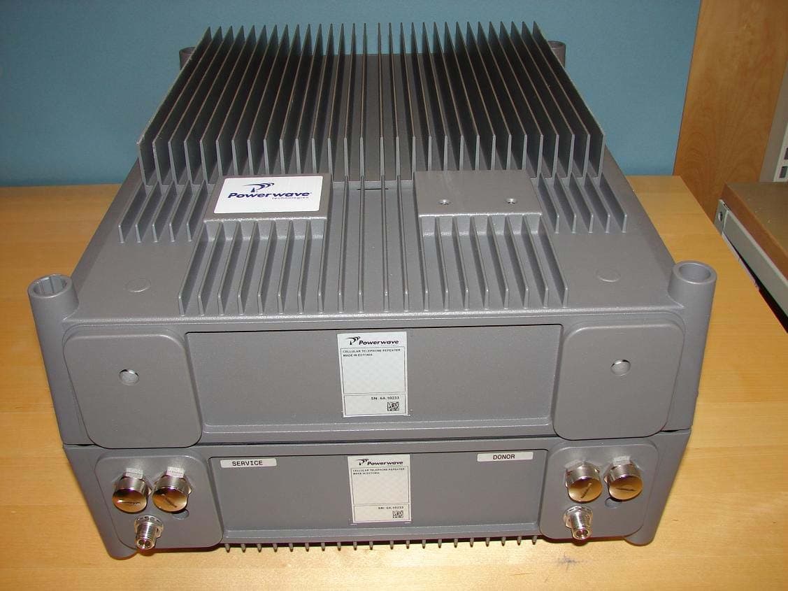
Click to zoom
Application Details
- Equipment Class
- TNB - Licensed Non-Broadcast Station Transmitter
- Date of Grant
- Jun 11, 2007
- Application Purpose
- Original Equipment
- Date of Application
- Jun 10, 2007
- Equipment Note
- 800 MHz Band Selective Repeater
- Frequency Range
- 851.00000000 - 869.00000000
- Company
- Powerwave Technologies Inc
- Country
- United States
Documents & Files
Document Text
Text extracted from the exhibit documents filed with the FCC. Open a document above to read the original.
Users Manual
044-05250 Rev A February 2007 Installation and Service Manual AR Standard Repeater © 2007 Powerwave Technologies Incorporated. All rights reserved. Powerwave Technologies and the Powerwave logo are registered trademarks. Powerwave Technologies Inc. reserves the right to make changes to the documentation and equipment, includ- ing but not limited to component substitution and circuitry changes. Changes that impact this document may subsequently be incorporated in a later revision of this document. This Powerwave product is designed to operate within the Normal Operating (typical operating) ranges or con- ditions specified in this document. Operation of this equipment beyond the specified ranges in this document may cause (1) spurious emissions that violate regulatory requirements; (2) the equipment to be automatically removed from service when maximum thresholds are exceeded; or (3) the equipment to not perform in accor- dance with its specifications. It is the Operator's responsibility to ensure this equipment is properly installed and operated within Powerwave operating specifications to obtain proper performance from the equipment and to comply with regulatory requirements. Federal Communications Commission (FCC) This equipment has been tested and found to comply with the limits for a Class A digital device, pursuant to part 15 of the FCC Rules. These limits are designed to provide reasonable protection against harmful interfer- ence when the equipment is operated in a commercial environment. This equipment generates, uses, and can radiate radio frequency energy and, if not installed and used in accordance with the instruction manual, may cause harmful interference to radio communications. Operation of this equipment in a residential area is likely to cause harmful interference in which case the user will be required to correct the interference at his own expense. Industry Canadian Requirement All Powerwave apparatus introduced on the Canadian market meet all requirements of the Canadian Interfer- ence-Causing Equipment Regulations. Powerwave Technologies Inc., 1801 East St. Andrew Place, CA 92705 Santa Ana, USA. Phone +1 714 466 1000 – Fax +1 714 466 5800 – Internet www.powerwave.com AR Standard RepeaterRevision Record 044-05250 Rev Ai Revision Record Revision Letter Date of ChangeReason for Change 3AAugust 2005Original VD203 66 AFebruary 2007Document number changed to 044-05250 and manual updated ii044-05250 Rev A This Page Intentionally Left Bank 044-05250 Rev Ai Table of Contents Abbreviations. . . . . . . . . . . . . . . . . . . . . . . . . . . . . . . . . . . . . . . . . . . . . . . . . . . . . . . . . . . . . . . . . . . . . . . . vi Chapter 1 - Product Description Introduction . . . . . . . . . . . . . . . . . . . . . . . . . . . . . . . . . . . . . . . . . . . . . . . . . . . . . . . . . . . . . . . . . . . . . . . .1-1 Scope of Manual . . . . . . . . . . . . . . . . . . . . . . . . . . . . . . . . . . . . . . . . . . . . . . . . . . . . . . . . . . . . . . . . . . . .1-1 Safety . . . . . . . . . . . . . . . . . . . . . . . . . . . . . . . . . . . . . . . . . . . . . . . . . . . . . . . . . . . . . . . . . . . . . . . . . . . .1-1 Warning Signs. . . . . . . . . . . . . . . . . . . . . . . . . . . . . . . . . . . . . . . . . . . . . . . . . . . . . . . . . . . . . . . . . . .1-2 Human Exposure of RF Radiation . . . . . . . . . . . . . . . . . . . . . . . . . . . . . . . . . . . . . . . . . . . . . . . . . . .1-2 Repeater Antennas. . . . . . . . . . . . . . . . . . . . . . . . . . . . . . . . . . . . . . . . . . . . . . . . . . . . . . . . . . . .1-2 Installation and Maintenance of Antenna Systems. . . . . . . . . . . . . . . . . . . . . . . . . . . . . . . . . . . .1-2 Radiation Exposure . . . . . . . . . . . . . . . . . . . . . . . . . . . . . . . . . . . . . . . . . . . . . . . . . . . . . . . . . . .1-2 Radiation Safety Distances . . . . . . . . . . . . . . . . . . . . . . . . . . . . . . . . . . . . . . . . . . . . . . . . . . . . . . . .1-3 Electrostatic Discharge (ESD) . . . . . . . . . . . . . . . . . . . . . . . . . . . . . . . . . . . . . . . . . . . . . . . . . . . . . .1-4 Overview . . . . . . . . . . . . . . . . . . . . . . . . . . . . . . . . . . . . . . . . . . . . . . . . . . . . . . . . . . . . . . . . . . . . . . . . . .1-5 Repeaters with RF / RF Transmission . . . . . . . . . . . . . . . . . . . . . . . . . . . . . . . . . . . . . . . . . . . . . . . .1-5 Channel Selective (CSel) Repeater . . . . . . . . . . . . . . . . . . . . . . . . . . . . . . . . . . . . . . . . . . . . . . .1-5 Band Selective (BSel) Repeater . . . . . . . . . . . . . . . . . . . . . . . . . . . . . . . . . . . . . . . . . . . . . . . . . .1-6 Repeaters with RF / Fiber Optic Transmission . . . . . . . . . . . . . . . . . . . . . . . . . . . . . . . . . . . . . . . . . .1-6 Base Station Master Unit (BMU) . . . . . . . . . . . . . . . . . . . . . . . . . . . . . . . . . . . . . . . . . . . . . . . . .1-6 Repeater Master Unit (RMU) . . . . . . . . . . . . . . . . . . . . . . . . . . . . . . . . . . . . . . . . . . . . . . . . . . . .1-6 Repeater with Fiber Optics / RF Transmission . . . . . . . . . . . . . . . . . . . . . . . . . . . . . . . . . . . . . . . . . .1-6 Combined Repeater . . . . . . . . . . . . . . . . . . . . . . . . . . . . . . . . . . . . . . . . . . . . . . . . . . . . . . . . . . . . . .1-6 Repeater Chassis Design . . . . . . . . . . . . . . . . . . . . . . . . . . . . . . . . . . . . . . . . . . . . . . . . . . . . . . . . . .1-6 Sub Unit Overview . . . . . . . . . . . . . . . . . . . . . . . . . . . . . . . . . . . . . . . . . . . . . . . . . . . . . . . . . . . . . . . . . . .1-7 Channel Amplifier PCBA for GSM and EDGE (CHE) . . . . . . . . . . . . . . . . . . . . . . . . . . . . . . . . . . . . .1-7 CDMA/WCDMA Segment Amplifier PCBA (CSA). . . . . . . . . . . . . . . . . . . . . . . . . . . . . . . . . . . . . . . .1-7 Band Selective Amplifier PCBA (BSA) . . . . . . . .…
Text truncated - open the document above for the full version.
External Photos
Repeater front & back side Repeater left & right side Repeater, labels outside
ID Label/Location Info
Repeater, labels outside
Operational Description
Utfärdare/Issued by Product Management Dattum/Date 2004-07-01 Godkänd/Approved Dok nr/Doc no AR4640/052-201 Rev A Sida/Page 1 Dok namn/Doc name PRELIMINARY PRODUCT SPECIFICATION Fil/file AR4640_052_A.doc Specification of a Band selective Repeater 800 IDEN/SMR, 16,9 MHz Bandwidth High Power Product number: AR4640/052 1. Electrical specification (typical values) The repeater complies with the requirements of FCC Frequency band Up link 806 – 824 MHz Frequency band Down link 851 - 869 MHz Duplex spacing 45 MHz Absolute group delay < 6 μs Gain adjustment range (1 dB steps) 45-85 dB Gain (max variation –25 to +55 ºC 6 dB Antenna isolation supervision Continuously Filter band width (remotely adjustable) 0.5-16,9 MHz Filter setting resolution 25 KHz Selectivity BW 3dB 16.9 MHz Selectivity BW 45dB BW 3dB + 1.2 MHz Selectivity BW 50dB BW 3dB + 2.2 MHz Pass band ripple 4 dB Output power, PEP +38 dBm Output power 2 carrier +33 dBm/carrier Max out of band spurious emission -13 dBm Automatic gain control Implemented Noise figure at 85 dB gain, 25° C (typical) 6 dB Maximum input power (non-destructive) +13 dBm Receiver input port return loss 14 dB Power supply voltage 115 V AC Power consumption, typ. (max) 320 W 2. Environmental specification Temperature range -25 to + 55 °C -13 to + 131 F Casing class NEMA4/IP65 3. Mechanical specification Dimensions. (W x H x D) 17.4 x 20.9 x 9.6 Inches 440 x 530 x 240 mm Mechanical outline See Standard High Weight 75 lbs 34 Kg RF connectors N-type female
Operational Description
DC voltages 13.5V and 5A for the final amplification devices.
Parts List/Tune Up Info
044-05250 Rev A4-1 Chapter 4 Maintenance Introduction This chapter contains periodic maintenance and performance test procedures for the AR Standard Repeater. Periodic Maintenance Periodic maintenance requirements are listed in Table 4-1, as well as the intervals at which the tasks should be performed. Table 4-1 Recommended Periodic Maintenance Troubleshooting The sections that follow contain a list of problems that could occur and a few suggested actions that can correct the problem. If the suggested corrective action does not eliminate the problem, please contact your Powerwave field representative or help line for further instruction. Clearing Alarm Faults Table 4-2 contains a list of those alarms which can be generated in the repeater. Critical, Error and Warning alarms can be sent automatically from a repeater to OM-Online and/or OMS, stored and then viewed. These can be viewed in the Alarm window. Table 4-2 Alarm Troubleshooting TaskIntervalAction Inspection of cables and con- nectors 12 monthsInspect power, RF and Fiber cables for signs of damage or wear (frayed insulation, cracks, punctures, etc.) Check con- nections to be sure they are tight. OptionalPerform cable sweeps. Clean equipmentClean as required depending on operating environment. IDAlarm Text Alarm Unit AlarmDescription 1PowerPSUCriticalPSU1 in the cabinet does not work properly. A sum signal from the PSU1 indicates that at least one volt- age output has dropped. If no mains breakdown relay is used, then the alarm will also be sent at mains breakdown. CeasingPSU1 in the cabinet works properly again. Ceasing is sent if the PSU1 works at start-up, and there is a cor- responding critical PSU1 alarm logged in the Events log. The repeater will restart when the power is back and this alarm will be sent. TroubleshootingAR Standard Repeater 4-2044-05250 Rev A PSUCriticalPSU2 in the cover does not work properly. A sum sig- nal from the PSU2 indicates that at least one voltage output has dropped. If no mains breakdown relay is used, then the alarm will also be sent at mains break- down. CeasingPSU2 in the cover works properly again. Ceasing is sent if the PSU2 works at start-up, and there is a cor- responding critical PSU2 alarm logged in the Events Log. The repeater will restart when the power is back and this alarm will be sent. FONErrorThe FON 10 Volt charger voltage is below limit. Sug- gested remedy: Replace the FON CeasingThe cause of the alarm has ceased. 2Repeater restart CUNonePower on start, or user ordered reboot. Logged to indicate a normal power up, or a restart ordered by the operator. WarningSoftware error restart, 1st – 7th time. Restart 1st to 7th time during a 14 day period. The counter is reset every 14th day, counted from power up. ErrorSoftware error restart 8th – 10th time. Restart 8th to 10th time during the 14 day period. At the 11th time, the SW bank will be blocked and not used anymore until a user ordered reset is performed, or power is switched off/on. 3Mains break- down Exter- nal CriticalThe mains power is gone. Used with an external relay indicating mains breakdown. The external relay should be connected to External Alarm 1 and the repeater configured to indicate this alarm. If no relay is used, a mains breakdown will be reported as a PSU fault. CeasingThe mains power is back. Sent if there is a corre- sponding critical mains breakdown alarm logged in the Events Log. The repeater will restart when the power is back. 4Alarm reset CUNoneAlarm reset by the user. All alarms are reset. The cause of the alarm will be re-evaluated and reported, if still active. 5Local bus error CHA #, BSA# ErrorError when communicating on the bus. The CU has no contact with the CHA or BSA PCBA, which is taken out of service. 6Main bkd w backup Exter- nal ErrorUsed to indicate that the mains is no longer available. Repeater is powered by external battery backup unit. Suggested remedy: Check the mains power. CeasingThe cause of the alarm has ceased. 7Err in AD- converter WarningThe analog-to-digital converter on the CU PCBA does not give reliable values. 8New unit detected NoneCompared to the last power on, the CU has recog- nized at least one additional hardware unit. AR Standard RepeaterTroubleshooting 044-05250 Rev A4-3 9Inst. unit lost ErrorCompared to the last power on, the CU lacks at least one hardware unit. 10EEPROM error CUErrorEEP read or write fail. Data cannot be written or read from the EEPROM on the CU PCBA. User parame- ters are stored in the EEPROM. 11Log mem- ory fault ErrorLog memory fault. Indicates that the log memory on the CU PCBA is faulty. The repeater will not work. Not available in all CU software versions. 12High tem- perature CUWarningThe CU PCBA temperature is higher than 90°C. CeasingThe CU PCBA temperature has fallen below 90°C. 13REFO error ErrorAR: Significant REFO drift or error detected by CU. ALR: Low level from REFO detected by CU. 14Ext refo error WarningSuggested remedy: Check the reference source and the cables. 15CU bat- tery fault CUWarningCU RAM battery fault. The battery for the RAM on the CU PCBA has a voltage outside the normal 2.7 to 3.5 Volt. An alarm may be initiated at start-up if the repeater has been stored out of power for a long time. Suggested remedy: Ensure jumper P3 on the CU PCBA is mounted to charge the battery. CeasingThe cause of the alarm has ceased. 16SW load error CUErrorSoftware load error. An error has occurred during a software load process. The flash memory does not contain a proper software. Suggested remedy: Check the CU software using the OM-Online SW Manager. Do NOT restart the repeater. 17Log cleared CUNoneLog memory has been cleared. The check sum in the Events Log memory is faulty. The log is cleared. Can be caused of a bad RAM battery backup or low volt- age to the RAM. 18RTC restarted CUNoneThe time is changed by the operator (logged to keep track of changes made to the RTC). WarningTime reset to 1994-01-01. The RTC was unable to keep track of the …
Text truncated - open the document above for the full version.
Test Report
Test report no. 704684R1 Page 2 (45) CONTENTS Page 1. Client information.............................................................................................................................3 2. Equipment under test (EUT)...........................................................................................................3 2.1 Identification of the EUT according to the manufacturer/client declaration...................3 2.2 Additional hardware information about the EUT...............................................................3 2.3 Additional software information about the EUT.................................................................4 2.4 Peripheral equipment............................................................................................................4 2.5 Modifications during the test................................................................................................4 2.6 Abbreviations..........................................................................................................................4 3. Test specifications...........................................................................................................................5 3.1 Standards................................................................................................................................5 3.2 Additions, deviations and exclusions from standards.......................................................5 3.3 Test set-up..............................................................................................................................5 3.4 Operating environment..........................................................................................................5 4.Test summary....................................................................................................................................6 5. RF output power...............................................................................................................................7 5.1 Test specification...................................................................................................................7 5.1 Test results.............................................................................................................................7 6. Occupied bandwidth........................................................................................................................9 6.1 Test specification...................................................................................................................9 6.2 Test results.............................................................................................................................9 7. Conducted spurious emissions at antenna port........................................................................12 7.1 Test specification.................................................................................................................12 7.2 Test results...........................................................................................................................12 8. Amplifier gain and bandwidth.......................................................................................................22 8.1 Test specification.................................................................................................................22 8.2 Test results...........................................................................................................................22 9. Mean output power (RSS-131)....................................................................................................25 9.1 Test specification.................................................................................................................25 9.2 Test results...........................................................................................................................25 10. Radiated spurious emissions.....................................................................................................27 10.1 Test specification...............................................................................................................27 10.2 Test equipment..................................................................................................................27 10.3 Measurement set-up.........................................................................................................28 10.5 Test results.........................................................................................................................30 11Conducted disturbance voltage in the frequency range 0,15 - 30 MHz.................................40 11.1 Measurement uncertainty.................................................................................................40 11.2 Test equipment..................................................................................................................40 11.3 Measurement set-up.........................................................................................................40 11.4 Test protocol.......................................................................................................................41 12 Instrumentation list........................................................................................................................43 13 Uncertainties summary................................................................................................................43 Appendix III – Photos of the EUT.....................................................................................................44 Test report no. 704684R1 Page 3 (45) 1. CLIENT INFORMATION The EUT has been tested by request of Company: Powerwave Technologies Sweden AB Antennvägen 7 SE-187 80 Täby Sweden Name of contact: Sven-Erik Söderberg 2. EQUIPMENT UNDER TEST (EUT) 2.1 Identification of the EUT acco…
Text truncated - open the document above for the full version.
Contact Information
Applicant
Jeff Dale(Principal Reliability Engineer)
Technical Contact
Intertek Testing ServicesMary Ellen Clayton
[email protected]209-966-5240
5046 Sierra Pines Dr. · Mariposa, California · United States
Test Firm
Intertek Testing ServicesUri Spector
Technical Specifications
| # | Rule Parts | Frequency Range | Power Output | Emission | Tolerance |
|---|---|---|---|---|---|
| 2 | 90,9 | 851 MHz - 869 MHz | 7.4 W | D7W | Amp |
Other Applications from Powerwave Technologies Inc

E675JS0123
Nov 03, 2011Multi-carrier RF Power Amplifier
Equipment Class
AMP - Amplifier
E675JS0120
Aug 26, 2010Nexus Dual Band Repeater
Equipment Class
TNB - Licensed Non-Broadcast Station Transmitter
E675JS0119
Aug 01, 2010Nexus Dual Band Repeater
Equipment Class
PCB - PCS Licensed Transmitter
E675JS0118
Jul 26, 2010Nexus Dual Band Repeater
Equipment Class
PCB - PCS Licensed Transmitter
E675JS0096
Jan 10, 2008Wideband Radio Head
Equipment Class
TNB - Licensed Non-Broadcast Station Transmitter