E675JS0097RF Power Amplifier Frame
Powerwave Technologies Inc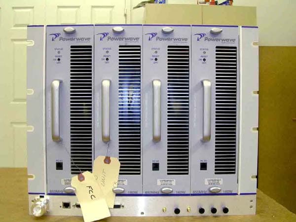
Click to zoom
Application Details
- Equipment Class
- AMP - Amplifier
- Date of Grant
- Jan 07, 2008
- Application Purpose
- Original Equipment
- Date of Application
- Jan 06, 2008
- Equipment Note
- RF Power Amplifier Frame
- Frequency Range
- 869.00000000 - 894.00000000
- Company
- Powerwave Technologies Inc
- Country
- United States
Documents & Files
Document Text
Text extracted from the exhibit documents filed with the FCC. Open a document above to read the original.
Users Manual
044-05287 Rev A April 2007 O F F P C I / O 850 MHz S T A T U S R E S E T O N Alcatel Lucent O F F P C I / O 850 MHz S T A T U S R E S E T O N Alcatel Lucent O F F P C I / O 850 MHz S T A T U S R E S E T O N Alcatel Lucent O F F P C I / O 850 MHz S T A T U S R E S E T O N Alcatel Lucent O F F P C I / O 850 MHz S T A T U S R E S E T O N Alc atel Luc ent O F F P C I / O 850 MHz S T A T U S R E S E T O N Alc atel Luc ent O F F P C I / O 850 MHz S T A T U S R E S E T O N Alc atel Luc ent O F F P C I / O 850 MHz S T A T U S R E S E T O N Alc atel Luc ent O F F P C I / O 850 MHz S T A T U S R E S E T O N Alc atel Luc ent O F F P C I / O 850 MHz S T A T U S R E S E T O N Alc atel Luc ent O F F P C I / O 850 MHz S T A T U S R E S E T O N Alc atel Luc ent O F F P C I / O 850 MHz S T A T U S R E S E T O N Alc atel Luc ent PAF-0813-E0-001 MCPA System Installation and Service Manual © 2007 Powerwave Technologies Incorporated. All rights reserved. Powerwave Technologies, and the Powerwave logo are registered trademarks. This Powerwave product is intended only for installation in a RESTRICTED ACCESS LOCATION and is designed to operate within the Normal Operating (typical operating) ranges or conditions specified in this document. Operation of this equipment beyond the specified ranges in this document may cause: 1. Spurious emissions that violate regulatory requirements. 2. The equipment to be automatically removed from service when maximum thresholds are exceeded. 3. The equipment to not perform in accordance with its specifications. It is the Operator's responsibility to ensure this equipment is properly installed and operated within Powerwave operat- ing specifications to obtain proper performance from the equipment and to comply with regulatory requirements. For PERMANENTLY CONNECTED EQUIPMENT, a readily accessible disconnect device shall be incorporated in the building installation wiring. PAF-0813-E0-001Warnings, Cautions, and Notes 044-05287 Rev Ai Warnings, Cautions, and Notes Warnings, Cautions, and Notes are found throughout this manual where applicable. The associated icons are used to quickly identify a potential condition that could result in the consequences described below if precautions are not taken. Notes clarify and provide additional information to assist the user. WARNING: This warning symbol means danger. You are in a situation that could cause bodily injury. Before you work on any equipment, be aware of the hazards involved with electrical and RF circuitry and be familiar with standard practices for preventing accidents CAUTION: This caution symbol means reader be careful. In this situation, the user might do something that could result in equipment damage or loss of data. NOTE This note symbol means reader take note. Notes contain helpful suggestions or references to material not covered in the document. Procedures are not contained in notes. Revision RecordPAF-0813-E0-001 ii044-05287 Rev A Revision Record Revision Letter Date of ChangeReason for Change AApril 2007Initial release 044-05287 Rev Ai Table of Contents Chapter 1 - Product Description Introduction ................................................................................................................................................... 1-1 Scope of Manual ........................................................................................................................................... 1-1 Product Description ....................................................................................................................................... 1-1 Functional And Physical Specifications ........................................................................................................ 1-1 Chapter 2 - Controls and Indicators Introduction ................................................................................................................................................... 2-1 Subrack ......................................................................................................................................................... 2-1 Ethernet Connector Pinout ..................................................................................................................... 2-2 RS-485 Interface .................................................................................................................................... 2-3 Filter I/O (if used) .................................................................................................................................... 2-3 MCPA ............................................................................................................................................................ 2-3 Filter (if used) ................................................................................................................................................ 2-4 Circuit Breaker Panel .................................................................................................................................... 2-6 Chapter 3 - Installation Introduction ................................................................................................................................................... 3-1 Site Survey .................................................................................................................................................... 3-1 Space Requirements .................................................................................................................................... 3-1 Unpacking and Inspection ............................................................................................................................. 3-1 Electrical Service Recommendations ........................................................................................................... 3-1 Cooling Requirements ........................................................................................................…
Text truncated - open the document above for the full version.
Users Manual
PAF-0813-E0-001Installation Instructions 044-05287 Rev A3-5 Figure 3-4 Frame to Halo Ground Connection Example RS-485 Alarm Interface The RS-485 alarm interface provides the BTS controller with system status via a 1 byte protocol. The baud rate is fixed at 15.6 K. Table 3-6 lists the available alarm states.. MCPA Install the MCPAs as instructed in Table 3-7. NOTE DO NOT remove metallic tape at frame top when connecting to Halo ground system. Removing tape voids PAF frame warranty. Table 3-4 RS-485 Alarm States AlarmStateDefinition No Alarm Minor AlarmAny or all fans fail Major AlarmAny one MCPA module disabled CriticalAll MCPA modules disabled CAUTION: REPLACE THIS SECTION WITH UPDATE Slamming or forcing the MCPA into the subrack may cause the pins on the 21-pin D-Sub connector to become recessed or broken. Ground Sticker To H a l o Ground To H a l o Ground Metallic Ta p e Initial Start-Up and Power Setting ProceduresPAF-0813-E0-001 3-6044-05287 Rev A Figure 3-5 MCPA Front Panel Features Initial Start-Up and Power Setting Procedures The following paragraphs provide initial startup, and power setting procedures. Initial Start Up To complete initial startup, perform the instructions listed in Table 3-8. Table 3-5 MCPA Installation Procedure StepAction 1.Inspect MCPA 21-pin connector. Verify all pins are straight, no pins are recessed, and alignment shield is not bent 2.Set MCPA power OFF/ON/RESET switch to OFF 3.Rotate MCPA quarter-turn fasteners counter-clockwise to unlock position shown in Figure 3-8 4.Install MCPA(s) into subrack. To secure each MCPA, rotate quarter-turn fasteners clockwise to lock position as shown in Figure 3-8 CAUTION: Excessive input power may damage MCPA. Before applying power, ensure MCPA inputs and outputs are properly terminated at 50 ohms. Do not operate MCPA without a load attached. Refer to Chapter 5 for input power requirements. Table 3-6 Initial Startup Procedure StepAction 1.Verify all input and output cables are properly connected 2.Turn on +27 VDC supply to MCPA 3.Set all MCPA front panel OFF/ON/RESET switches to ON (middle) position 4.Allow MCPAs to warm up for at least two minutes before taking power readings Unlocked Locked LED Status Indicator RF Switch: RESET ON OFF Quarter-Turn Fasteners ON OFF ON OFF Alcatel Lucent Alcatel Lucent 044-05287 Rev A4-1 Chapter 4 Maintenance Introduction This chapter contains periodic maintenance and performance test procedures for the PAF-081X-P0-001 Multi- Carrier Power Amplifier (MCPA) system. Periodic Maintenance Periodic maintenance requirements are listed in Table 4-1, as well as the intervals at which the tasks should be performed. Troubleshooting The following paragraphs contain a list of problems that could occur and a few suggested actions that can correct the problem. If the suggested corrective action does not eliminate the problem, please contact your Powerwave field representative or the factory for further instructions. NOTE Do not break seals on equipment under warranty or warranty will be null and void. Do not return equipment for warranty or repair service until factory shipping instructions are received. Table 4-1 Periodic Maintenance TaskIntervalAction Inspection: Cables and Connec- tors 12 MonthsInspect signal and power cables for frayed insulation. Check RF connectors to be sure that they are tight OptionalAntenna VSWR sweep Cleaning: Fans and Equipment Clean as required depending on equipment operating environment System Component Part NumbersPAF-0813-E0-001 4-2044-05287 Rev A Clearing Alarm Faults Setting the MCPA front panel OFF/ON/RESET switch to RESET can clear many alarm faults. An attempt to reset the MCPA should be your first course of action. 24-Hour technical support service is available at our main phone number 888-797-9283 or 714-466-1000; select the "System Operator Technical Support" option to receive assistance from Powerwave's Applications Support Group. Refer to Table 4-2 for troubleshooting suggestions. System Component Part Numbers Table 4-3 lists the model/part numbers for ordering individual system components and manuals. Field Replacement Procedures The following parts and modules can be replaced in the field on site by a qualified technician with experience maintaining RF power amplifiers and similar equipment: Table 4-2 Troubleshooting ProblemSuggested Action MCPA Inoperative (MCPA front panel LED red) 1.Set MCPA OFF/ON/RESET toggle switch momentarily to RESET 2.Check for proper power supply voltage 3.Verify all RF connections 4.Contact your field representative or factory Table 4-3 System Components Part Number List Model/Part NumberManual NumberDescription System Maximum Quantity G3L-830-160-160 Watt, 850 MHz MCPA12 800-09666-001-Subrack Fan Assembly2 per subrack MCR40830-1-4-Subrack, 4-way combined3 800-07829-002-Panel, blank, MCPAas required FIL-0830A-Filter, 850 MHz, A-band3 FIL-0830B-Filter, 850 MHz, B-band3 800-11185-600-Panel, Circuit Breaker 1 1002530-Circuit Breaker, 50 A12 1002529-Circuit Breaker, 15 A2 700-18766-001-Cable, RF, 7/16 DIN-R-MA 3 700-18767-001-Cable, Filter, DB-15 to DB-153 700-18133-100-Cable, Filter, DC1 ❑ MCPA ❑ Fiter ❑ Cooling Fans ❑ Circuit Breaker Panel ❑ Subrack PAF-0813-E0-001Field Replacement Procedures 044-05287 Rev A4-3 MCPA To replace an MCPA module, shown in Figure 4-1, perform the steps in Table 4-3. Figure 4-1 MCPA Removal and Replacement CAUTION: To prevent damage to MCPA rear connector, support rear of MCPA when removing from subrack. The MCPA weight is approximately 20 lbs (9.1 kg). Table 4-4 MCPA Removal and Replacement Procedure StepAction 1.Set MCPA front panel OFF/ON/RESET switch to OFF 2.Rotate MCPA module quarter-turn fasteners counterclockwise 3.With steady even pressure, use handle on front of MCPA to pull module out of enclosure as shown in Figure 4-1 4.Replace MCPA module in reverse order of removal S T A T U S RESET S T A T U S RESET S TAT U S RESET PC I/O PC I/O P C I / O S T A T U S R E S E T P C I / O O N O F F Alc at…
Text truncated - open the document above for the full version.
Cover Letter(s)
Non-Conformities FCC ID: E675JS0097 (CKC CS Ref # E07-000131-FCC-01) The items listed below represent requests for information following review of this application for certification under United S tates (FCC) regulations. Further question may arise pending review of responses to these items. OK # Non-Conformity or Co mment Submitted Response Respondent / Date of Response * FCC Notes: Ref KDB 754507 X 1 The application form and the ID Label information indicate FCC ID: E67JS0097, however the confidentiality letter references E675JS0087. Please clarify which is correct and submit corrections as necessary. A revised confidentiality letter has been uploaded. X 2 Please separate the external photos which show the external views of the subrack from the provided internal photos exhibit. The photos have been separated and uploaded. X 3 Please clarifiy power output measurements on page: output power measurements are not aggregate condu cted - eg power is measured per individual carrier per subrack? Yes per subrack. Each subrack has its own RF output port where power was measured. X 4 The output power listing for F9W emissions is listed on the application for as 640 W, however the test re port states only 500 W. Please confirm which is correct. 500 W is correct. 5
External Photos
Amplifier Front Amplifier Back Amplifier Top Amplifier Bottom Amplifier Side 1 Amplifier Side 2
External Photos
Card Cage Front Card Cage Back Card Cage Top Card Cage Bottom Card Cage Side 1 Card Cage Side 2
Operational Description
DC Voltages 27 Vdc, 3A into the multi-carrier amplifier module output devices.
Operational Description
044-05287 Rev A1-1 Chapter 1 Product Description Introduction This manual contains information and procedures for installation, operation, and maintenance of the PAF- 0813-E0-001 Multi-Carrier Power Amplifier (MCPA) Indoor System. The manual is organized into chapters as follows. Scope of Manual This manual is intended for use by service technicians familiar with similar types of equipment. It contains service information required for the equipment described and is current as of the printing date. Changes which occur after the printing date may be incorporated by a complete manual revision or alternatively as additions. Product Description The PAF-0813-E0-001 system, shown in the Figure 1-1 block diagram, is an 850 MHz, 4-way combined, frame-mounted BTS solution. The PAF system contains three MCPA subracks, each capable of containing up to four MCPAs, three filters, and one DC circuit breaker panel. The MCPA subrack, shown in Figure 1-3, contains linear, feed-forward MCPAs that operate in the 869 - 894 MHz range. Each subrack is also equipped with automatic power control (APC), an ethernet connection, an RS-485/RS-232 connection, a filter I/O port, and two cooling fans. The subrack is installed on sliding rails so that it can be pulled forward to allow access to the rear of the subrack. The MCPA, shown in Figure 1-4, is an 850 MHz module that produces a typical output of 160 watts (52.0 dBm) before system losses, with an instantaneous bandwidth of 25 MHz. The filter assembly, shown in Figure 1-5, if used, supresses unwanted signals and non-linear components of the signal from the amplifiers. The circuit breaker panel, shown in Figure 1-8, consists of two +27 VDC input buses (A and B), and a system circuit breaker panel. The panel receives +27 VDC from the BTS and then distributes circuit breaker protected DC power to the individual subracks. Functional And Physical Specifications PAF-081X-P0-001 system functional and physical specifications are listed in Chapter 5. ❑ Chapter 1 - Product Description ❑ Chapter 2 - Controls and Indicators ❑ Chapter 3 - Installation ❑ Chapter 4 - Maintenance ❑ Chapter 5 - Specifications
Parts List/Tune Up Info
Initial Start-Up and Power Setting ProceduresPAF-0813-E0-001 3-6044-05287 Rev A Figure 3-5 MCPA Front Panel Features Initial Start-Up and Power Setting Procedures The following paragraphs provide initial startup, and power setting procedures. Initial Start Up To complete initial startup, perform the instructions listed in Table 3-8. Table 3-5 MCPA Installation Procedure StepAction 1.Inspect MCPA 21-pin connector. Verify all pins are straight, no pins are recessed, and alignment shield is not bent 2.Set MCPA power OFF/ON/RESET switch to OFF 3.Rotate MCPA quarter-turn fasteners counter-clockwise to unlock position shown in Figure 3-8 4.Install MCPA(s) into subrack. To secure each MCPA, rotate quarter-turn fasteners clockwise to lock position as shown in Figure 3-8 CAUTION: Excessive input power may damage MCPA. Before applying power, ensure MCPA inputs and outputs are properly terminated at 50 ohms. Do not operate MCPA without a load attached. Refer to Chapter 5 for input power requirements. Table 3-6 Initial Startup Procedure StepAction 1.Verify all input and output cables are properly connected 2.Turn on +27 VDC supply to MCPA 3.Set all MCPA front panel OFF/ON/RESET switches to ON (middle) position 4.Allow MCPAs to warm up for at least two minutes before taking power readings Unlocked Locked LED Status Indicator RF Switch: RESET ON OFF Quarter-Turn Fasteners ON OFF ON OFF Alcatel Lucent Alcatel Lucent
RF Exposure Info
5473A Clouds Rest Road : Mariposa, CA 95338 : Phone 209-966-5420 : Fax 209-742-6133 Maximum Permissible Exposure Calculations Date of Report: 1/11/07 Calculations prepared for: Powerwave Technologies 1801 E. St. Andrew Place Santa Ana, CA 92705 Calculations prepared by: Eddie Wong 110 N. Olinda Place Brea, CA 9283 Model Number: PAF-08XX-XXX FCC Identification: NA Fundamental Operating Frequency: 1930-1990 MHz Maximum Rated Output Power: 555Watts Measured Output Power: 500Watts MPE Limit in accordance with 1.1310(b): Limits for general population/uncontrolled exposure MPE Limit for 869 - 894 MHz = f/1500 = 0.6 mW/cm 2 (6 W/m 2 ) Power Output (Watts) Power Density Limit (mW/cm 2 ) Minimum Distance (Meters) 500 0.6 2.6 P t = Power Delivered to the Antenna G = Antenna Gain d = Distance in meters Zo = Impedance of Free Space The typical antennas to be used with the EUT are structure mount antennas which under normal operation has an antenna height of at least 5 meters. As can be seen from the MPE result, this device passes the limit specified in 1.1310 at a distance of 2.6 meter. Calculation: = 2.6meter. 377 x 6 1 500 30xx d= 0 2 t 2 x Zd G x P x 30 )(W/m Density Power=
Test Report
Page 1 of 64 Report No.: FC07-004 POWERWAVE TECHNOLOGIES, INC. TEST REPORT FOR THE POWER AMPLIFIER FRAME, PAF-08XX-XXX FCC PART 22 COMPLIANCE DATE OF ISSUE: JANUARY 16, 2007 PREPARED FOR: Powerwave Technologies, Inc. 1801 E. St. Andrew Place Santa Ana, CA 92705 PREPARED BY: Mary Ellen Clayton CKC Laboratories, Inc. 5046 Sierra Pines Drive Mariposa, CA 95338 P.O. No.: 110980 W.O. No.: 85903 Date of test: November 14, 2006- January 11, 2007 Report No.: FC07-004 This report contains a total of 64 pages and may be reproduced in full only. Partial reproduction may only be done with the written consent of CKC Laboratories, Inc. The results in this report apply only to the items tested, as identified herein. Page 2 of 64 Report No.: FC07-004 TABLE OF CONTENTS Administrative Information .............................................................................................3 Approvals .........................................................................................................................3 Conditions for Compliance ..............................................................................................3 Equipment Under Test (EUT) Description ......................................................................4 Equipment Under Test .....................................................................................................4 Peripheral Devices ...........................................................................................................4 Temperature and Humidity During Testing.....................................................................5 FCC 2.1033(c)(3) User’s Manual ....................................................................................5 FCC 2.1033(c)(4) Type of Emissions ..............................................................................5 FCC 2.1033(c)(5) Frequency Range................................................................................5 FCC 2.1033(c)(6) Operating Power.................................................................................5 FCC 2.1033(c)(7) Maximum Power Rating ....................................................................5 FCC 2.1033(c)(8) DC Voltages .......................................................................................5 FCC 2.1033(c)(9) Tune-Up Procedure ............................................................................5 FCC 2.1033(c)(10) Schematics and Circuitry Description..............................................5 FCC 2.1033(c)(11) Label and Placement ........................................................................5 FCC 2.1033(c)(12) Submittal Photos ..............................................................................5 FCC 2.1033(c)(13) Modulation Information ...................................................................5 FCC 2.1033(c)(14)/2.1046/22.913 - RF Power Output ...................................................6 FCC 2.1033(c)(14)/2.1051/22.917(a) - Spurious Emissions at Antenna Terminal .........8 FCC 2.1033(c)(14)/2.1053/22.917(a) - Field Strength of Spurious Radiation ................19 Input Plots ........................................................................................................................28 Output Plots .....................................................................................................................34 Blockedge Plots ...............................................................................................................40 Intermodulation Plots.......................................................................................................47 Appendix A: Additional Testing: FCC 15.109 Class A ..................................................51 Page 3 of 64 Report No.: FC07-004 ADMINISTRATIVE INFORMATION DATE OF TEST: November 14, 2006- January 11, 2007 DATE OF RECEIPT: November 14, 2006 FREQUENCY RANGE TESTED: 9 kHz-9 GHz MANUFACTURER: Powerwave Technologies, Inc. 1801 E. St. Andrew Place Santa Ana, CA 92705 REPRESENTATIVE: Jeffrey Dale TEST LOCATION: CKC Laboratories, Inc. 110 Olinda Place Brea, CA 92823 TEST METHOD: FCC Part 22 PURPOSE OF TEST: To demonstrate the compliance of the Power Amplifier Frame, PAF-08XX-XXX with the requirements for FCC Part 22 devices. APPROVALS: Steve Behm, Director of Engineering Services QUALITY ASSURANCE:TEST PERSONNEL: Joyce Walker, Quality Assurance Administrative Manager Eddie Wong, EMC Engineer CONDITIONS FOR COMPLIANCE No modifications to the EUT were necessary to comply. Page 4 of 64 Report No.: FC07-004 EQUIPMENT UNDER TEST (EUT) DESCRIPTION The customer declares the EUT tested by CKC Laboratories was representative of a production unit. EQUIPMENT UNDER TEST Power Amplifier Frame Manuf: Powerwave Technologies, Inc. Model: PAF-08XX-XXX Serial: NA PERIPHERAL DEVICES The EUT was tested with the following peripheral device(s): Power Supply Manuf: Power Ten Model: NA Serial: NA Spectrum Analyzer Manuf: HP Model: 8563E Serial: NA Power Meter Manuf: Agilent Model: E4419B Serial: MY40510694 ESG Manuf: Agilent Model: E4433B Serial: US40053250 & US40051840 Page 5 of 64 Report No.: FC07-004 TEMPERATURE AND HUMIDITY DURING TESTING The temperature during testing was within +15°C and + 35°C. The relative humidity was between 20% and 75%. FCC 2.1033(c)(3) USER’S MANUAL The necessary information is contained in a separate document. FCC 2.1033 (c)(4) TYPE OF EMISSIONS F1D, F8W, F9W FCC 2.1033 (c)(5) FREQUENCY RANGE 869 MHz – 894 MHz FCC 2.1033 (c)(6) OPERATING POWER 500 Watts FCC 2.1033 (c)(7) MAXIMUM POWER RATING 500 Watts FCC 2.1033 (c)(8) DC VOLTAGES The necessary information is contained in a separate document. FCC 2.1033 (c)(9) TUNE-UP PROCEDURE The necessary information is contained in a separate document. FCC 2.1033(c)(10)SCHEMATICS AND CIRCUITRY DESCRIPTION The necessary information is contained in a separate document. FCC 2.1033(c)(11) LABEL AND PLACEMENT The necessary information is contained in a separa…
Text truncated - open the document above for the full version.
Contact Information
Applicant
Jeff Dale(Principal Reliability Engineer)
Technical Contact
CKC Laboratories, Inc.`Mary Ellen Clayton
[email protected]209-966-5240
5046 Sierra Pines Dr. · Mariposa, California · United States
Test Firm
CKC Laboratories, Inc.Steve Behm
Technical Specifications
| # | Rule Parts | Frequency Range | Power Output | Emission | Tolerance |
|---|---|---|---|---|---|
| 2 | 22 | 869 MHz - 894 MHz | 500 W | F1D | Amp |
Other Applications from Powerwave Technologies Inc

E675JS0123
Nov 03, 2011Multi-carrier RF Power Amplifier
Equipment Class
AMP - Amplifier
E675JS0120
Aug 26, 2010Nexus Dual Band Repeater
Equipment Class
TNB - Licensed Non-Broadcast Station Transmitter
E675JS0119
Aug 01, 2010Nexus Dual Band Repeater
Equipment Class
PCB - PCS Licensed Transmitter
E675JS0118
Jul 26, 2010Nexus Dual Band Repeater
Equipment Class
PCB - PCS Licensed Transmitter
E675JS0096
Jan 10, 2008Wideband Radio Head
Equipment Class
TNB - Licensed Non-Broadcast Station Transmitter