EEX-FL-8Camera
G.G.Telecom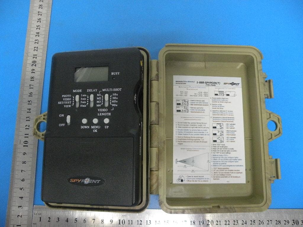
Click to zoom
Application Details
- Equipment Class
- DSC - Part 15 Security/Remote Control Transmitter
- Date of Grant
- Sep 05, 2013
- Application Purpose
- Original Equipment
- Date of Application
- Sep 05, 2013
- Equipment Note
- Camera
- Frequency Range
- 433.92000000 - 433.92000000
- Company
- G.G.Telecom
- Country
- Canada
Documents & Files
Document Text
Text extracted from the exhibit documents filed with the FCC. Open a document above to read the original.
Users Manual
Digital Surveillance Camera Système de surveillance photographique FL-8 model / Modèle FL-8 User manual / Manuel d'utilisation www.spypoint.com 23 English English v1.0 English Thank you for choosing the SPYPOINT FL-8 monitoring system. This manual will help you get the most out of your new device. For the latest version of the user manual or for additional information, visit our website at www.spypoint.com. If you need information or to subscribe to mySPYPOINT service, go to www.myspypoint.com. 45 English English FEATURES Photo recording: Photo resolution8 MP File formatJPG Multi-shotUp to 4 pictures per detection StampDate, time, temperature and moon phase Capture modeColor by day and night (with flash) Black and white by night (with IR) Video recording: Note: It is recommended to use the IR unit when the camera is set to « VIDEO » mode. Video resolution640 x 480 File formatAVI Sequence lengthAdjustable from 10 to 90sec Capture modeColor by day, black and white by night (with IR) *Video available at night with the IR unit only Sound recording: Automatically recorded in video mode Memory storage: SD/SDHC card up to 32 GB (No internal memory) Viewing: TV outputComposite video (PAL/NTSC) Computer outputUSB 2.0 Power supply: (accessories sold separately, see section «OPTIONS») Alkaline or lithium batteries 6x AA Lithium battery packRechargeable battery pack (LIT-09/LIT-C-8) External (12V jack)12-volt battery (KIT-12V/BATT-12) / 12-volt adapter (AD-12V) Solar panelSolar panel (SP-12V) combined with rechargeable battery pack (LIT-09) Detection system: Motion sensorPIR Detection angle30° Detection rangeAdjustable from 5 to 50ft Delay between each detection Adjustable from 1 to 15min *Additional 10 sec. setting (see DELAY) Night time illumination system: LEDs35 LEDs TypeInfrared LEDs FlashFlash unit Optical field of view: 50° Recommendations: Operating temperature(-20 °C to + 50 °C) (-4 °F to +122 °F) Storage temperature(-30 °C to + 75 °C) (-22 °F to +167 °F) CONTENTS • SPYPOINT FL-8 • Flash unit • IR unit • Installation strap • USB cable • Audio-video cable • User manual 67 English English POWER The battery level is shown in the lower left corner of the LCD screen. When a single line remains, the camera will continue to take pictures but we strongly recommend changing the batteries before they are empty. (See figure below) AA BATTERIES This camera requires the use of 6 AA batteries (1.5V). The use of alkaline or lithium batteries is strongly recommended. During the installation of AA batteries, place the switch inside the battery case to «ALK» (i.e. alkaline). Insert the batteries as indicated inside the battery case. Exact polarity must be followed. We also recommend the use of new batteries to ensure maximum performance of your camera. LITHIUM BATTERY PACK The camera can be powered by a rechargeable lithium battery LIT- 09/LIT-C-8 (sold separately, see section «OPTIONS»). This type of battery is less affected by cold temperatures and lasts up to 3 times longer than an alkaline battery. During the installation of lithium battery, place the switch inside the battery case to «RECH» . EXTERNAL (12V) The camera can be powered from an external 12-volt DC input such as a 12-volt battery (KIT-12V/BATT-12V, sold separately) or a 12-volt adapter (AD-12V, sold separately). When using a 12-volt connection, we recommend removing the AA batteries to prevent surcharges. During the installation of a 12-volt connection, place the switch inside the battery case to «ALK» (i.e. alkaline). If combined with a lithium battery pack, slide the switch to «RECH». To find the accessories available for the 12-volts, see section «OPTIONS». SOLAR PANEL This model also offers the possibility of a connection to a solar panel SP-12V (sold separately, see section «OPTIONS») to maintain the charge of the lithium battery pack LIT-09/LIT-C-8 (sold separately, see section «Options»). During the installation of the rechargeable lithium battery, slide up the switch inside the battery case up to « RECH » to activate the charging system of the solar panel. MEMORY STORAGE Using a memory card (sold separately, see section «OPTIONS») is required to operate the camera. When the camera is «ON» and no memory card is used, the LCD panel displays «CArd» meaning to insert one. The camera is compatible with SD/SDHC memory card, up to 32 GB capacity. Before inserting or removing a memory card, the camera must be turned off. Failing to do so may cause loss of pictures or damage the pictures already saved on the memory card. When the SD card is full, the LCD panel indicates «FULL». The following data shows an approximate quantity of photos which can be recorded by the camera depending on the memory card capacity. RESOLUTION2.0 GB4.0 GB8.0 GB32 GB 3 MP 8 MP 2000 1200 4100 2400 8200 4800 32800 19000 VIDEO RESOLUTION 320 x 240 640 x 480 2h 65 min 4h 2h10 8h 4h10 32h 16h40 « BUSY » LED The « BUSY » light, located next to the screen, lights up when the camera is recording. SETTINGS Date, Time, Temperature and Picture Quality Turn «OFF» your camera; set switch «MODE» to «SET/TEST » and turn «ON» the camera and press «MENU/ OK». An «H» will flash on the screen indicating that the camera is in High Resolution (8 MP). Use the «DOWN» button if you want to reduce the resolution to «L» (3 MP). Press «MENU/OK» to set the date and time (mm/dd/yy, hh/mm). Use «UP» and «DOWN» to change the blinking digit. Choose «F» or «C» to display the temperature in Fahrenheit (°F) or Celsius (°C). Press «MENU/OK» to move to the next option. With the «UP» button, choose «ON» or «OFF» to enable or disable the MS-1. This option allows to trigger the camera remotely using one or more MS-1 devices. (see section «Options» for more details) 89 English English Press «MENU/OK» to move to the next option. With the «UP» button, choose «ON» or «OFF» to enable or disable the IR- BOOSTER. This option allows the camera to trigger, up to a distance of 50 ft, one or more remote IR-BOOSTER in…
Text truncated - open the document above for the full version.
Attestation Statements
G.G.Telecom Federal Communications Commission Authorization and Evaluation Division 1435 Oakland Mills Road Columbia, MD 21046 Date: SUBJECT: FCC Application for ( FCC ID: EEX -FL-8 ) To Whom It May Concern: We, the undersigned, hereby attest to the fact that we will apply the Declaration of Conformity procedure to the class B computer peripheral portion of this composite device. We understand that devices subject to the DoC procedure are required to be tested to show compliance with the FCC technical regulations by a recognized accredited testing laboratory. The testing laboratory must be accredited by a Commission approved accreditation body or designated under the terms of a government-to-government Mutual Recognition Agreement (MRA). A listing of those accredited testing laboratories that have been recognized by the Commission is published on the FCC Webpage: https://apps.fcc.gov/oetcf/eas/reports/TestFirmSearch.cfm Select the "accredited" option to search for FCC recognized accredited test firms. Test facilities located in countries, where the U.S. does not have an operational Telcom MRA are not recognized by the FCC to test for the DoC procedure. Regards, Signatory Signature Date:2013/7/22 Name: Yan Gagnon Title: President Tel: 514 868 1811 Company: G.G.Telecom
Cover Letter(s)
Differences Description We G.G.Telecom state: Product name: Camera Model: FL-8, 2N1 All model’s the function, software and electric circuit are the same , only with a product color and model named different. Signatory Signature Date:2013/7/22 Name: Yan Gagnon Title: President Tel: 514 868 1811 Company: G.G.Telecom
Cover Letter(s)
G.G.Telecom SCS-F18: Project and Product Certification Representative Authorization Letter Page 1 of 2 Rev 3.0 775 Montague Expressway Milpitas, CA 95035 Tel: 408-526-1188 Fax: 408-526-1088 Email: [email protected] Project and Product Certification Representative Authorization Letter Reason for Amendment (current / obsolete) Revision History Approved Date From To Initial Release (obsolete) 1.0 1.0 Nov-14-2006 Revised wording (obsolete) 1.0 2.0 Sept–25-2007 Updated company template (current) 2.0 3.0 Jan-31-2012 G.G.Telecom SCS-F18: Project and Product Certification Representative Authorization Letter Page 2 of 2 Rev 3.0 2013/7/22 To: SIEMIC, INC. 775 Montague Expressway, Milpitas, CA 95035 USA Dear Sir/Madam, Re: Project and Product Certification Representative Authorization Letter We, G.G.Telecom hereby authorize SIEMIC, INC. to act as a Certification Body for certifying for the following project(s): Product: Camera Model Name: FL-8, 2N1 Trade Name: SPYPOINT FCC ID: EEX-FL-8 We affirm that between SIEMIC and ___ G.G.Telecom_, any difference in understanding, including test plan, measurement methods, applicable standards and relevant procedures and processes have been resolved prior to commencement of testing activities. Sincerely, Client’s signature Signature Date:2013/7/22 Name: Yan Gagnon Title: President Tel: 514 868 1811 Company: G.G.Telecom
Cover Letter(s)
G.G.Telecom SCS-F19: Confidentiality Request Letter Page 1 of 2 Rev 3.0 775 Montague Expressway Milpitas, CA 95035 Tel: 408-526-1188 Fax: 408-526-1088 Email: [email protected] Confidentiality Request Letter Reason for Amendment (current / obsolete) Revision History Approved Date From To Initial Release (obsolete) 1.0 1.0 Nov-14-2006 Adding CFR 2.459 (obsolete) 1.0 2.0 August – 11 - 2008 Updated company template & Added text box (current) 2.0 3.0 Jan-31-2012 G.G.Telecom SCS-F19: Confidentiality Request Letter Page 2 of 2 Rev 3.0 2013/7/22 To: Federal Communications Commission Authorization and Evaluation Division 7435 Oakland Mills Road Columbia, MD Subject: Permanent Confidentiality Request for FCC ID: EEX-FL-8 We hereby request confidential treatment of information accompanying this application as outlined below: - Block Diagram - Schematics - Operational Description The above materials contain trade secrets and proprietary information not customarily released to the public. The public disclosure of these materials may be harmful to the applicant and provide unjustified benefits to its competitors. The applicant understands that pursuant to Section 0.457 & 0.459 of the Rules, disclosure of this application and all accompanying documentation will not be made before the date of the Grant for this application. Sincerely, Client’s signature Signature Date:2013/7/22 Name: Yan Gagnon Title: President Tel: 514 868 1811 Company: G.G.Telecom
External Photos
EUT View EUT View EUT View EUT View EUT View EUT View EUT View EUT View
ID Label/Location Info
Label: Label Location FCC ID: EEX-FL-8 This device complies with Part 15 of the FCC Rules. Operation is subject to the following two conditions: (1) this device may not cause harmful interference, and (2) this device must accept any interference received, including interference that may cause undesired operation.
Internal Photos
Top View Top View Bottom View Top View Bottom View Top View Top View Bottom View Bottom View Top View Top View Bottom View Antenna
Test Report
FCC RADIO TEST REPORT FCC ID: EEX-FL-8 Product: Camera Trade Name: SPYPOINT Model Name: FL-8, 2N1 Serial Model: N/A Report No.: BZT-2013NT0705023F Prepared for G.G.Telecom 120 Rue J-Aurele-Roux, Victoriaville, Quebec G6T 0N5,Canada Prepared by Shenzhen NTEK Testing Technology Co., Ltd. 1/F, Building E, Fenda Science Park, Sanwei Community,Xixiang Street Bao’an District, Shenzhen P.R. China Tel.: +86-0755-61156588 Fax.: +86-0755-61156599 Website:www.ntek.org.cn Page 2 of 31 Report No.: BZT-2013NT0705023F ` TEST RESULT CERTIFICATION Applicant’s name ................. : G.G.Telecom Address ................................. : 120 Rue J-Aurele-Roux, Victoriaville, Quebec G6T 0N5,Canada Manufacturer........................ G.G.Telecom Address.............................. 120 Rue J-Aurele-Roux, Victoriaville, Quebec G6T 0N5,Canada Product description Product name............................ : Camera Model and/or type reference : FL-8, 2N1 Serial Model: N/A Rating(s) ................................ : DC 9V from battery or DC 12V from adapter with AC 120V/60Hz Standards ............................. : FCC Part15.231 Test procedure ............................... : ANSI C63.4-2003 This device described above has been tested by NTEK, and the test results show that the equipment under test (EUT) is in compliance with the FCC requirements. And it is applicable only to the tested sample identified in the report. This report shall not be reproduced except in full, without the written approval of NTEK, this document may be altered or revised by NTEK, personal only, and shall be noted in the revision of the document. Date of Test ........................................... : Date (s) of performance of tests ............. : 05 July. 2013 ~11 July. 2013 Date of Issue .......................................... : 12 July. 2013 Test Result.............................................. : Pass Testing Engineer : (Apple Huang) Technical Manager : (Tom Zhang) Authorized Signatory : (Bovey Yang) Page 3 of 31 Report No.: BZT-2013NT0705023F ` Table of Contents Page 1 . SUMMARY OF TEST RESULTS 4 1.1 TEST FACILITY 5 1.2 MEASUREMENT UNCERTAINTY 5 2 . GENERAL INFORMATION 6 2.1 GENERAL DESCRIPTION OF EUT 6 2.2 DESCRIPTION OF TEST MODES 7 2.3 BLOCK DIGRAM SHOWING THE CONFIGURATION OF SYSTEM TESTED 8 2.4 DESCRIPTION OF SUPPORT UNITS(CONDUCTED MODE) 9 2.5 EQUIPMENTS LIST FOR ALL TEST ITEMS 10 3 . ANTENNA REQUIREMENT 11 3.1 STANDARD REQUIREMENT 11 3.2 EUT ANTENNA 11 3.3 CONDUCTED EMISSION MEASUREMENT 12 3.3.1 POWER LINE CONDUCTED EMISSION LIMITS 12 3.3.2 TEST PROCEDURE 13 3.3.3 DEVIATION FROM TEST STANDARD 13 3.3.4 TEST SETUP 13 3.2.5 TEST RESULT 14 3.3.5 TEST RESULTS 14 3.4 RADIATED EMISSION MEASUREMENT 16 3.4.1 RADIATED EMISSION LIMITS 16 3.4.2 TEST PROCEDURE 17 3.4.3 DEVIATION FROM TEST STANDARD 17 3.4.4 TEST SETUP 18 3.4.5 TEST RESULTS (BELOW 30MHZ) 20 3.4.6 TEST RESULTS (BETWEEN 30 – 1000 MHZ) 21 4 . BANDWIDTH TEST 26 4.1 TEST PROCEDURE 26 4.2 DEVIATION FROM STANDARD 26 4.3 TEST SETUP 26 4.4 TEST RESULTS 27 5 . TRANSMITTER TIMEOUT 28 5.1 REQUIREMENTS 28 6 . EUT TEST PHOTO 30 APPENDIX-PHOTOGRAPHS OF EUT CONSTRUCTIONAL DETAILS Page 4 of 31 Report No.: BZT-2013NT0705023F ` 1. SUMMARY OF TEST RESULTS Test procedures according to the technical standards: FCC Part15, Subpart C (15.231) Standard Section Test Item Judgment Remark 15.207 Conducted Emission Pass 15.203 Antenna Requirement Pass 15.231 Radiated Spurious Emission Pass 15.231 Occupied Bandwidth Pass 15.231 Transmitter Timeout Pass NOTE: (1) ” N/A” denotes test is not applicable in this Test Report. Page 5 of 31 Report No.: BZT-2013NT0705023F ` 1.1 TEST FACILITY NTEK Testing Technology Co., Ltd Add. : 1/F, Building E, Fenda Science Park, Sanwei Community, Xixiang Street, Bao’an District, Shenzhen P.R. China. FCC Registered No.: 238937 IC Registered No.:9270A-1 CNAS Registration No.:L5516 1.2 MEASUREMENT UNCERTAINTY The reported uncertainty of measurement y ± U,where expended uncertainty U is based on a standard uncertainty multiplied by a coverage factor of k=2,providing a level of confidence of approximately 95 %。 No. Item Uncertainty 1 Conducted Emission Test ±1.38dB 2 RF power,conducted ±0.16dB 3 Spurious emissions,conducted ±0.21dB 4 All emissions,radiated(<1G) ±4.68dB 5 All emissions,radiated(>1G) ±4.89dB 6 Temperature ±0.5°C 7 Humidity ±2% Page 6 of 31 Report No.: BZT-2013NT0705023F ` 2. GENERAL INFORMATION 2.1 GENERAL DESCRIPTION OF EUT Equipment Camera Trade Name SPYPOINT Model Name FL-8, 2N1 Serial Model N/A Model Difference All model’s the function, software and electric circuit are the same , only with a product color and model named different Product Description The EUT is a Camera Product Type Low Power Communication Device Transmitter Operation Frequency: 433.92MHz Modulation Type: ASK Number Of Channel 1CH. Antenna Designation: internal Antenna Antenna Gain(Peak) 1dBi Output Power: 76.64 dBuV/m (AV Max.) More details of EUT technical specification, please refer to the User's Manual. Channel List N/A Adapter Output: DC 12V Battery DC 9V Note: 1. For a more detailed features description, please refer to the manufacturer’s specifications or the User's Manual. 2. Table for Filed Antenna Ant . Brand Model Name Antenna Type Connector Gain (dBi) NOTE 1 N/A N/A internal Antenna N/A 1 Antenna Page 7 of 31 Report No.: BZT-2013NT0705023F ` 2.2 DESCRIPTION OF TEST MODES To investigate the maximum EMI emission characteristics generates from EUT, the test system was pre-scanning tested base on the consideration of following EUT operation mode or test configuration mode which possible have effect on EMI emission level. Each of these EUT operation mode(s) or test configuration mode(s) mentioned above was evaluated respectively. Pretest Mode Description Mode 1 TX For Conducted Emission Final Test Mode Description Mode 1 TX For Radiated Emission Final Test Mode Description Mode 1 TX Note: (1) The EUT use new battery. (2) The EUT is set to Continuous emission by short s…
Text truncated - open the document above for the full version.
Test Setup Photos
Radiated Emission Test Setup in Chamber Conducted Emission Test Setup
Contact Information
Applicant
Yan Gagnon(President)
Test Firm
Shenzhen NTEK Testing Technology Co., Ltd.Jason Chen
Technical Specifications
| # | Rule Parts | Frequency Range | Power Output |
|---|---|---|---|
| 1 | 15.231 | 433.92 MHz - 433.92 MHz | - |
Other Applications from G.G.Telecom

EEX-MLIVE
Jun 30, 2015Surveillance Camera
Equipment Class
PCB - PCS Licensed Transmitter
EEX-MINI-LIVE
Oct 13, 2014Surveillance Camera
Equipment Class
PCB - PCS Licensed Transmitter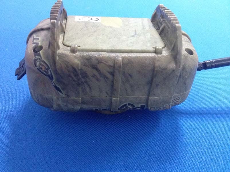
EEX-MS-1
Nov 19, 2013WIRELESS MOTION SENSOR
Equipment Class
DSC - Part 15 Security/Remote Control Transmitter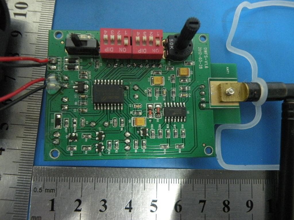
EEX-WRLB
Sep 11, 2013Monitoring System
Equipment Class
DSC - Part 15 Security/Remote Control Transmitter
EEX-TINY-W3
Sep 02, 2013TINY Camera
Equipment Class
DSC - Part 15 Security/Remote Control Transmitter