EEX-MLIVESurveillance Camera
G.G.Telecom
Click to zoom
Application Details
- Equipment Class
- PCB - PCS Licensed Transmitter
- Date of Grant
- Jun 30, 2015
- Application Purpose
- Original Equipment
- Date of Application
- Jun 30, 2015
- Equipment Note
- Surveillance Camera
- Frequency Range
- 1851.25000000 - 1908.75000000
- Company
- G.G.Telecom
- Country
- Canada
Documents & Files
Document Text
Text extracted from the exhibit documents filed with the FCC. Open a document above to read the original.
Users Manual
Quick start guide Cellular trail camera Models: Mini-LIVE Mini-LIVE-4G Mini-LIVE-4GV Mini-LIVE-CV In the box 1 2 3 5 4 Components Note: Memory card and batteries are sold separately. * Mini-LIVE and Mini-LIVE-4G only Included for United States, Canada and United Kingdom only Navigation buttons Microphone (Mini-LIVE-4G, Mini-LIVE-4GV and Mini-LIVE- CV) Power button 12V/Solar panel jack USB port SIM card slot (Mini-LIVE and Mini-LIVE-4G) SD card slot Built -in speaker (Mini-LIVE-4G, Mini-LIVE-4GV and Mini-LIVE- CV) Photo lens Invisible LEDs Test light Battery case Detection lens Mounting bracket Slot for installation str ap T ripod mount Cable lock hole BUSY LED Viewing screen 1 2 3 4 5 6 7 8 9 10 11 12 9 1011121314 13 14 15171916 18 15 16 17 18 19 3. INSERT THE MEMORY CARD Insert an SD/SDHC memory card (up to 32 GB capacity) in the card slot, gold contacts facing up. The card is inserted correctly when a click is heard. Before inserting or removing a memory card, always turn off the camera to prevent loss or damage of the photos already recorded. 4. INSERT THE SIM CARD (MINI-LIVE AND MINI-LIVE-4G) A SIM card is required to use cellular functions. Carefully insert a SIM card in the card slot, gold contact area facing down. The card is inserted correctly when a click is heard. Before inserting or removing a SIM card, always turn off the camera. 5. INSTALL THE CAMERA WITH THE SUPPLIED STRAP Recommended installation height: about 3 feet above the ground. Do not place the camera facing the sun. 1. Insérez l’extrémité de la courroie dans la fente qui se trouve au dos du mécanisme. 2. Insérez la courroie dans la fente sous le levier et faites-la ressortir en arrière. 3. Créer une tension sur la courroie en la tirant vers la droite, puis rabattez vers la gauche le levier pour maintenir la position. 1. REMOVE CAMERA FROM THE MOUNTING BRACKET A. Push the tab to release the camera from the mounting bracket. B. Remove the camera. 2. CHOOSE A POWER SOURCE In order to get best results and longer battery life, we recommend the use of an external 12V source. For easier access to the 12V jack, remove the camera from the mounting bracket before plugging a 12V cable. Then, the camera can be reinstalled in the mounting bracket. Rechargeable AA batteries are not recommended. Getting started 6 8 7 A. B. • Lithium battery pack LIT-09/LIT-C-8 • 6 alkaline AA batteries • 12V power source v1.4 1-888-779-7646 support.spypoint.com [email protected] Installation strap USB cable Camera Quick start guide SIM card* Mounting bracket 2 1 Using your fingers, push down on each side of the battery compartment's tab to open it. The battery compartment adapts to SPYPOINT LIT-09 lithium battery pack or 6 AA alkaline batteries. Therefore, it is important to be careful while inserting AA batteries. E. Set the Transmission mode option (Mini-LIVE only) • MySPYPOINT: The camera communicates with the mySPYPOINT server to update its status or to send photos to the user account. MySP YPOINT subscription is required. Activation procedure available at support.spypoint.com/ activation. • MMS: The camera communicates by MMS to update its status or to send photos. Enter up to 5 different phone numbers to which the MMS will be sent. The country code and area code must be entered. One MMS is charged for each recipient. A MMS plan is required, available from a compatible cellular service provider. Activation procedure available at support.spypoint.com/activation. • Email: The camera communicates by email to update its status or to send photos. Enter up to 5 different email addresses to which notifications will be sent. A data plan is required, available from a cellular service provider. Activation procedure available at support.spypoint.com/activation . F. S et the Frequency option. Allows the user to choose the number of synchronizations that the camera performs in a day. G. S et the First synch time option. Allows the user to choose at what time of the day the camera communicates for the first time. E.g.: If the "Frequency" option is set to 6/day and "First synch time" at 04:00, the camera performs 6 synchronizations per day and first starts sending at 4 h, 8 h, 12 h, 16 h, 20 h and 24 h. 2. CONFIGURE THE WIRELESS SETTINGS A. In the main menu, select SETTINGS and then, WIRELESS to access the Wireless settings menu. B. S et the Cellular option. Activate this option to send photos by cellular transmission. Activation procedure available at support.spypoint.com/activation For Mini-LIVE-4GV and Mini-LIVE-CV camera, go directly to F step. C. S et the Country option. The country where the camera is used must be selected. D. Set the Provider option. The provider selected must correspond with the SIM card used in the camer a. For Mini-LIVE-4G camera, go directly to F step. Power sourceLIT-09 charger option • 6 AA • 12V • 12V + 6 AA OFF • LIT-09* • 12V + LIT-09* • Solar panel + LIT-09* ON * Rechargeable lithium battery pack, sold separately (LIT-09) or with a charger (LIT-C-8). Use the h and buttons to navigate in the interface and to change options. Use the OK button to confirm and the button to return to the previous menu. 1. CONFIGURE THE GENERAL SETTINGS A. Turn on the camera by pressing the power button. B. In the main menu, select SETTINGS and then GENERAL to access to the General settings menu. C. Set the Date format (MM/DD/YY or DD/MM/YY) and the Date. D. Set the Time format (12H/24H) and the Time (Hour/Minute). E. Set the Schedule option. This option allows the user to set the period of operation of the camera for each day of the week. F or a 24 hour operation, the same start and stop times must be entered as followed (e.g.: 00:00/00:00). F. Set the LIT-09 charger option depending on the power source (see next table). Settings PERFORM THE STEPS 4 TO 6 DURING THE FINAL INSTALLATION OF THE CAMERA. 4. TEST THE DETECTION OF THE CAMERA When the TEST mode is selected, no photo or video is recorded. Pass in front of the camera …
Text truncated - open the document above for the full version.
Attestation Statements
From: Charlie Williams [mailto] Sent: Monday, September 22, 2014 9:53 PM To: PCTEST Subject: Re: Question Regarding Contact Person for Documents on a Telit Module Hi George, My R&D team confirms this is average power, not the peak power for an instantaneous point in time. We calibrate these to the average seen across both bands and at multiple channels within a band (i.e., so its not a single calibration point) per the tolerance we list in the tune up. Please let me know any further questions around this topic! Regards, Charlie Williams FAE Manager Telit Wireless Solutions, Inc.
External Photos
G.G. Telecom FCC ID: EEX-MLIVE Model: Mini-LIVE-CV External Photos EUT Type: Surveillance Camera Page 1 of 4 © 2015 PCTEST Engineering Laboratory, Inc. V 2.5 03/20/2015 EXTERNAL PHOTOGRAPHS G.G. Telecom FCC ID: EEX-MLIVE Model: Mini-LIVE-CV External Photos EUT Type: Surveillance Camera Page 2 of 4 © 2015 PCTEST Engineering Laboratory, Inc. V 2.5 03/20/2015 G.G. Telecom FCC ID: EEX-MLIVE Model: Mini-LIVE-CV External Photos EUT Type: Surveillance Camera Page 3 of 4 © 2015 PCTEST Engineering Laboratory, Inc. V 2.5 03/20/2015 G.G. Telecom FCC ID: EEX-MLIVE Model: Mini-LIVE-CV External Photos EUT Type: Surveillance Camera Page 4 of 4 © 2015 PCTEST Engineering Laboratory, Inc. V 2.5 03/20/2015
ID Label/Location Info
FCC ID Label Location The label is a permanent adhesive placed in the battery case. Note that it’s not a removable part of the camera and its readily visible (see image attached).
Internal Photos
G.G. Telecom FCC ID: EEX-MLIVE Model: Mini-LIVE-CV Internal Photos EUT Type: Surveillance Camera Page 1 of 8 © 2015 PCTEST Engineering Laboratory, Inc. V 2.5 03/20/2015 INTERNAL PHOTOGRAPHS G.G. Telecom FCC ID: EEX-MLIVE Model: Mini-LIVE-CV Internal Photos EUT Type: Surveillance Camera Page 2 of 8 © 2015 PCTEST Engineering Laboratory, Inc. V 2.5 03/20/2015 G.G. Telecom FCC ID: EEX-MLIVE Model: Mini-LIVE-CV Internal Photos EUT Type: Surveillance Camera Page 3 of 8 © 2015 PCTEST Engineering Laboratory, Inc. V 2.5 03/20/2015 G.G. Telecom FCC ID: EEX-MLIVE Model: Mini-LIVE-CV Internal Photos EUT Type: Surveillance Camera Page 4 of 8 © 2015 PCTEST Engineering Laboratory, Inc. V 2.5 03/20/2015 G.G. Telecom FCC ID: EEX-MLIVE Model: Mini-LIVE-CV Internal Photos EUT Type: Surveillance Camera Page 5 of 8 © 2015 PCTEST Engineering Laboratory, Inc. V 2.5 03/20/2015 G.G. Telecom FCC ID: EEX-MLIVE Model: Mini-LIVE-CV Internal Photos EUT Type: Surveillance Camera Page 6 of 8 © 2015 PCTEST Engineering Laboratory, Inc. V 2.5 03/20/2015 G.G. Telecom FCC ID: EEX-MLIVE Model: Mini-LIVE-CV Internal Photos EUT Type: Surveillance Camera Page 7 of 8 © 2015 PCTEST Engineering Laboratory, Inc. V 2.5 03/20/2015 G.G. Telecom FCC ID: EEX-MLIVE Model: Mini-LIVE-CV Internal Photos EUT Type: Surveillance Camera Page 8 of 8 © 2015 PCTEST Engineering Laboratory, Inc. V 2.5 03/20/2015
RF Exposure Info
FCC ID: EEX-MLIVE MAXIMUM PERMISSIBLE EXPOSURE (MPE) DATA REPORT Reviewed by: Quality Manager Test Report S/N: Test Dates: EUT Type: Page 1 of 7 0Y1505080839.EEX 5/19 - 5/26/2015 Surveillance Camera © 2015 PCTEST Engineering Laboratory, Inc. REV 3.2MPE 7/27/2012 Applicant Name: Date of Testing: G.G. Telecom 5/19 - 5/26/2015 120 J-Aurèle-Roux Test Site/Location: Victoriaville, QC G6T0N5 PCTEST Lab, Columbia, MD, USA Canada Test Report Serial No.: 0Y1505080839.EEX FCC ID: EEX-MLIVE APPLICANT: G.G. Telecom EUT Type: Surveillance Camera FCC Rule Part(s): FCC Part 1 (§1.1310) and Part 2 (§2.1091) FCC Classification: PCS Licensed Transmitter (PCB) Test Procedure: OET Bulletin 65 The device bearing the FCC Identifier specified above has been shown to comply with the applicable technical standards as indicated in the measurement report and has been tested in accordance with the measurement procedures specified in FCC OET Bulletin 65 (See Test Report). These measurements were performed with no deviation from the standards. Test results reported herein relate only to the item(s) tested. I authorize and attest to the accuracy of data. All measurements reported herein were performed by me or were made under my supervision and are correct to the best of my knowledge and belief. I assume full responsibility for the completeness of these measurements and vouch for the qualifications of all persons taking them. PCTEST ENGINEERING LABORATORY, INC. 6660-B Dobbin Road, Columbia, MD 21045 USA Tel. 410.290.6652 / Fax 410.290.6554 http://www.pctestlab.com RF EXPOSURE EVALUATION Maximum Permissible Exposure (MPE) FCC ID: EEX-MLIVE MAXIMUM PERMISSIBLE EXPOSURE (MPE) DATA REPORT Reviewed by: Quality Manager Test Report S/N: Test Dates: EUT Type: Page 2 of 7 0Y1505080839.EEX 5/19 - 5/26/2015 Surveillance Camera © 2015 PCTEST Engineering Laboratory, Inc. REV 3.2MPE 7/27/2012 TABLE OF CONTENTS 1.0 RF EXPOSURE EVALUATION – MAXIMUM PERMISSIBLE EXPOSURE (MPE) ......................... 3 1.1 INTRODUCTION ................................................................................................................................... 3 1.2 EUT DESCRIPTION .............................................................................................................................. 3 1.3 MPE REQUIREMENTS OVERVIEW ..................................................................................................... 4 1.4 PROCEDURE ........................................................................................................................................ 5 1.5 SUMMARY OF RESULTS ..................................................................................................................... 5 2.0 CONCLUSION .................................................................................................................................. 7 FCC ID: EEX-MLIVE MAXIMUM PERMISSIBLE EXPOSURE (MPE) DATA REPORT Reviewed by: Quality Manager Test Report S/N: Test Dates: EUT Type: Page 3 of 7 0Y1505080839.EEX 5/19 - 5/26/2015 Surveillance Camera © 2015 PCTEST Engineering Laboratory, Inc. REV 3.2MPE 7/27/2012 1.0 RF EXPOSURE EVALUATION – MAXIMUM PERMISSIBLE EXPOSURE (MPE) 1.1 Introduction This document is prepared on behalf of G.G. Telecom to show compliance with the RF Exposure requirements as required in §1.1310 of the FCC Rules and Regulations and RSS-102 of Industry Canada. The limit for Maximum Permissible Exposure (MPE), specified in FCC §1.1310, is listed in Table 1-1. According to FCC §1.1310 and RSS-102: the criteria listed in the following table shall be used to evaluate the environmental impact of human exposure to radio-frequency (RF) radiation as specified in §1.1307(b). Frequency Range (MHz) Electric Field Strength (V/m) Magnetic Field Strength (A/m) Power Density (mW/cm 2 ) Average Time (Minutes) (A) Limits For Occupational / Control Exposures (f = frequency) 30-300 61.4 0.163 1.0 6 300-1500 ... ... f/300 6 1500-100,000 ... ... 5.0 6 (B) Limits For General Population / Uncontrolled Exposure (f = frequency) 30-300 27.5 0.073 0.2 30 300-1500 ... ... f/1500 30 1500-100,000 ... ... 1.0 30 Table 1-1. Limits for Maximum Permissible Exposure (MPE) 1.2 EUT Description The G.G.Telecom Model: Mini-LIVE-CV is a Surveillance Camera containing a previously certified Telit CDMA/EvDO module (FCC ID: RI7DE910-DUAL). EUT: Model: Mini-LIVE-CV Grantee: G.G. Telecom FCC ID: EEX-MLIVE Antenna(s): Please see technical description for list of available antenna options FCC ID: EEX-MLIVE MAXIMUM PERMISSIBLE EXPOSURE (MPE) DATA REPORT Reviewed by: Quality Manager Test Report S/N: Test Dates: EUT Type: Page 4 of 7 0Y1505080839.EEX 5/19 - 5/26/2015 Surveillance Camera © 2015 PCTEST Engineering Laboratory, Inc. REV 3.2MPE 7/27/2012 1.3 MPE Requirements Overview Three different categories of transmitters are defined by the FCC in OET Bulletin 65. These categories are fixed installation, mobile, and portable and are defined as follows: o Fixed Installations: fixed location means that the device, including its antenna, is physically secured at a permanent location and is not able to be easily moved to another location. Additionally, distance to humans from the antenna is maintained to at least 2 meters. o Mobile Devices: a mobile device is defined as a transmitting device designed to be used in other than fixed locations and to be generally used in such a way that a separation distance of at least 20 centimeters is normally maintained between the transmitter's radiating structures and the body of the user or nearby persons. Transmitters designed to be used by consumers or workers that can be easily re-located, such as a wireless modem operating in a laptop computer, are considered mobile devices if they meet the 20 centimeter separation requirement. The FCC rules for evaluating mobile devices for RF compliance are found in 47 CFR §2.1091. o Portable Devices: a portable device is defined as a transmitting device designed to be used so that…
Text truncated - open the document above for the full version.
Test Report
FCC ID: EEX-MLIVE FCC Pt. 22 & 24 CDMA MEASUREMENT REPORT (CERTIFICATION) Reviewed by: Quality Manager Test Report S/N: Test Dates: EUT Type: Page 1 of 40 0Y1505080837.EEX 5/19 - 5/26/2015 Surveillance Camera © 2015 PCTEST Engineering Laboratory, Inc. V 2.5 03/20/2015 Applicant Name: Date of Testing: G.G. Telecom 5/19 - 5/26/2015 120 J-Aurèle-Roux Test Site/Location: Victoriaville, QC G6T0N5 PCTEST Lab., Columbia, MD, USA Canada Test Report Serial No.: 0Y1505080837.EEX FCC ID: EEX-MLIVE APPLICANT: G.G. TELECOM Application Type: Certification Model(s): Mini-LIVE-CV EUT Type: Surveillance Camera FCC Classification: PCS Licensed Transmitter (PCB) FCC Rule Part(s): §2 §22(H) §24(E) Test Procedure(s): ANSI/TIA-603-C-2004, KDB 971168 v02r02 Test Device Serial No.: identical prototype [S/N: 8MAY-1, 29MAY-1] This equipment has been shown to be capable of compliance with the applicable technical standards as indicated in the measurement report and was tested in accordance with the measurement procedures specified in §2.947. Test results reported herein relate only to the item(s) tested. I attest to the accuracy of data. All measurements reported herein were performed by me or were made under my supervision and are correct to the best of my knowledge and belief. I assume full responsibility for the completeness of these measurements and vouch for the qualifications of all persons taking them. CDMA850 824.70 - 848.31 1M27F9W 0.10720.29 CDMA1900 1851.25 - 1908.75 1M27F9W 0.07118.51 Emission Designator Tx Frequency (MHz) Mode ERP/EIRP Max. Power (W) Max. Power (dBm) PCTEST ENGINEERING LABORATORY, INC. 7185 Oakland Mills Road, Columbia, MD 21046 USA Tel. 410.290.6652 / Fax 410.290.6654 http://www.pctestlab.com MEASUREMENT REPORT FCC Part 22 & 24 FCC ID: EEX-MLIVE FCC Pt. 22 & 24 CDMA MEASUREMENT REPORT (CERTIFICATION) Reviewed by: Quality Manager Test Report S/N: Test Dates: EUT Type: Page 2 of 40 0Y1505080837.EEX 5/19 - 5/26/2015 Surveillance Camera © 2015 PCTEST Engineering Laboratory, Inc. V 2.5 03/20/2015 TABLE OF CONTENTS FCC PART 22 & 24 MEASUREMENT REPORT .......................................................................................... 3 1.0 INTRODUCTION .............................................................................................................................. 4 1.1 SCOPE ................................................................................................................................................ 4 1.2 TESTING FACILITY ............................................................................................................................. 4 2.0 PRODUCT INFORMATION .............................................................................................................. 5 2.1 EQUIPMENT DESCRIPTION .............................................................................................................. 5 2.2 DEVICE CAPABILITIES....................................................................................................................... 5 2.3 TEST CONFIGURATION ..................................................................................................................... 5 2.4 EMI SUPPRESSION DEVICE(S)/MODIFICATIONS ........................................................................... 5 3.0 DESCRIPTION OF TESTS .............................................................................................................. 6 3.1 EVALUATION PROCEDURE .............................................................................................................. 6 3.2 CELLULAR - BASE FREQUENCY BLOCKS ....................................................................................... 6 3.3 CELLULAR - MOBILE FREQUENCY BLOCKS ................................................................................... 6 3.4 PCS - BASE FREQUENCY BLOCKS .................................................................................................. 6 3.5 PCS - MOBILE FREQUENCY BLOCKS .............................................................................................. 7 3.6 RADIATED MEASUREMENTS ............................................................................................................ 7 4.0 TEST EQUIPMENT CALIBRATION DATA ...................................................................................... 8 5.0 SAMPLE CALCULATIONS .............................................................................................................. 9 6.0 TEST RESULTS ............................................................................................................................. 10 6.1 SUMMARY ......................................................................................................................................... 10 6.2 TRANSMITTER OUTPUT POWER ................................................................................................... 11 6.3 OCCUPIED BANDWIDTH ................................................................................................................. 12 6.4 SPURIOUS AND HARMONIC EMISSIONS AT ANTENNA TERMINAL ............................................ 14 6.5 BAND EDGE EMISSIONS AT ANTENNA TERMINAL ...................................................................... 21 6.6 PEAK-AVERAGE RATIO ................................................................................................................... 26 6.7 RADIATED POWER (ERP/EIRP) ...................................................................................................... 28 6.8 RADIATED SPURIOUS EMISSIONS MEASUREMENTS ................................................................. 30 6.9 FREQUENCY STABILITY / TEMPERATURE VARIATION ............................................................... 35 7.0 CONCLUSION ................................................................................................................................ 40 FCC ID: EEX-MLIVE FCC Pt. 22 & 24 CDMA MEASURE…
Text truncated - open the document above for the full version.
Test Setup Photos
G.G. Telecom FCC ID: EEX-MLIVE Model: Mini-LIVE-CV Test Set-Up Photos EUT Type: Surveillance Camera Page 1 of 2 © 2015 PCTEST Engineering Laboratory, Inc. V 1.23 09/24/2014 TEST SETUP PHOTOGRAPHS G.G. Telecom FCC ID: EEX-MLIVE Model: Mini-LIVE-CV Test Set-Up Photos EUT Type: Surveillance Camera Page 2 of 2 © 2015 PCTEST Engineering Laboratory, Inc. V 1.23 09/24/2014
Contact Information
Applicant
Yan Gagnon(President)
Technical Contact
PCTEST Engineering Laboratory, Inc.Randy Ortanez
[email protected]410-290-6652
6660-B Dobbin Road · Columbia, Maryland · United States
Test Firm
PCTEST Engineering Laboratory, Inc.Randy Ortanez
Technical Specifications
| # | Rule Parts | Frequency Range | Power Output | Emission | Tolerance |
|---|---|---|---|---|---|
| 2 | 24E | 1.85 GHz - 1.91 GHz | 71.00 mW | 1M27F9W | 2.5 ppm |
Other Applications from G.G.Telecom

EEX-MINI-LIVE
Oct 13, 2014Surveillance Camera
Equipment Class
PCB - PCS Licensed Transmitter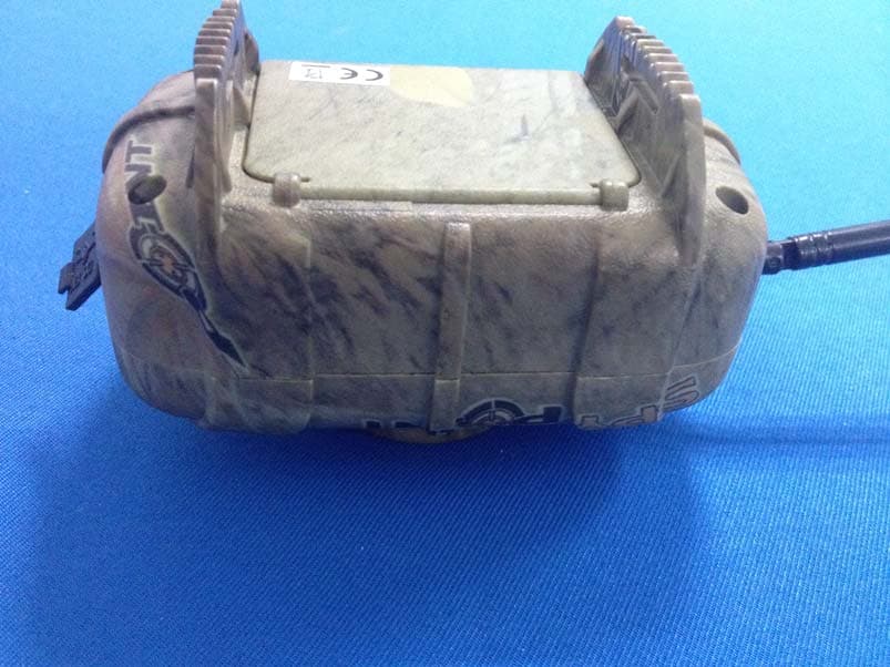
EEX-MS-1
Nov 19, 2013WIRELESS MOTION SENSOR
Equipment Class
DSC - Part 15 Security/Remote Control Transmitter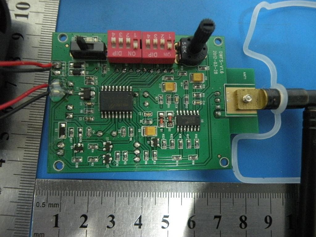
EEX-WRLB
Sep 11, 2013Monitoring System
Equipment Class
DSC - Part 15 Security/Remote Control Transmitter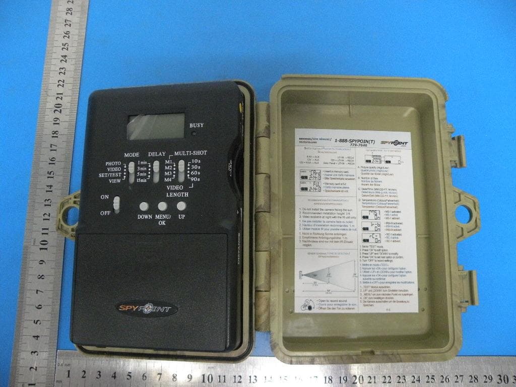
EEX-FL-8
Sep 05, 2013Camera
Equipment Class
DSC - Part 15 Security/Remote Control Transmitter
EEX-TINY-W3
Sep 02, 2013TINY Camera
Equipment Class
DSC - Part 15 Security/Remote Control Transmitter