EEX-MS-1WIRELESS MOTION SENSOR
G.G.Telecom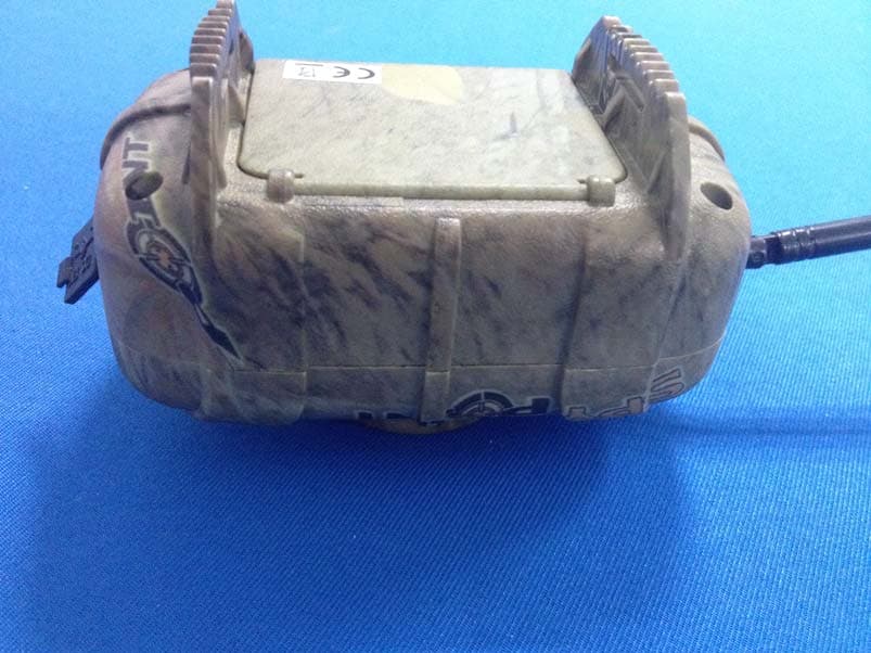
Click to zoom
Application Details
- Equipment Class
- DSC - Part 15 Security/Remote Control Transmitter
- Date of Grant
- Nov 19, 2013
- Application Purpose
- Original Equipment
- Date of Application
- Nov 19, 2013
- Equipment Note
- WIRELESS MOTION SENSOR
- Frequency Range
- 433.92000000 - 433.92000000
- Company
- G.G.Telecom
- Country
- Canada
Documents & Files
Document Text
Text extracted from the exhibit documents filed with the FCC. Open a document above to read the original.
Users Manual
MS-1/S-MS-1 PI NTSPYI NTPSPY Capteur de mouvement sans fil MS-1/S-MS-1 PI NTSPYI NTPSPY Wireless motion sensor SÉLECTEUR «TEST» Le sélecteur «TEST» permet de vérifier la distance maximale à laquelle la caméra peut être installée du capteur. Installer le capteur à sa surface fixe et glisser vers le haut le sélecteur «TEST». Éloigner la caméra (préalablement mise en mode «TEST») du capteur de mouvement. Si la lumière «TEST» de la caméra arrête de flasher, c'est que celle-ci est en dehors de la distance maximale de fonctionnement avec le capteur. BOUTON «DISTANCE» Le bouton «DISTANCE» permet de régler la sensibilité du capteur de mouvement sans fil. Pour augmenter la sensibilité, tourner le bouton dans le sens horaire. Pour la diminuer, tourner dans le sens antihoraire. La distance maximale de détection d’une cible en mouvement est d’environ 15 mètres. SYNCHRONISATION DES APPAREILS Pour synchroniser les appareils d'un même ensemble, régler premièrement chaque appareil à la même fréquence de communication (1 à 7). Placer ensuite le sélecteur de mise sous tension à la position "ON" pour chaque appareil; un délai d'environ 20 secondes peut s'écouler avant que les appareils soient synchronisés et puissent communiquer ensemble. GARANTIE LIMITÉE Le capteur de mouvement sans fil SPYPOINT MD MS-1/ S-MS-1, conçu par GG Telecom, est couvert d’une garantie d’un (1) an incluant les pièces et la main d’oeuvre à compter de la date d’achat. Le coupon de caisse est la preuve d’achat et devra être présenté si la garantie est applicable. La garantie ne couvre pas les produits de GG Telecom ayant subi des abus, de la négligence, des accidents ou de mauvaises utilisations ou entretiens. Toutes modifications ou utilisations non conformes du produit affecteront son fonctionnement, ses performances, sa durabilité et annuleront la garantie. SERVICE DE RÉPARATION Les réparations pour bris ou défectuosités non couverts par la garantie seront facturées à prix raisonnables. Pour le soutien technique, s.v.p. écrire un courriel à [email protected]. Décrire le problème rencontré et indiquer un numéro de téléphone pour vous rejoindre. IMPORTANT: En aucune circonstance, GG Telecom n’acceptera de réparation sans un numéro d’autorisation. WWW.SPYPOINT.COM Note: Pour la plus récente mise à jour du manuel d’utilisateur, référez-vous à notre site Web. v1.1 The MS-1/S-MS-1 wireless motion sensor allows to trigger the camera remotely, up to 500ft away. It is therefore possible to increase the surveillance zone by positioning the MS-1 device away from your camera, while continuing to use the built-in motion sensor of the camera. RECOMMENDATIONS • Install the sensor (s) at about 3 feet above the ground (for use in hunting). • Install the sensor (s) on a stationary surface. • When storing the unit for more than 30 days, remove the batteries from the system. FEATURES • Works with all cameras compatible with Remos ® technology. • Several sensors can be used with the same cameras. • The maximum operating distance between a wireless motion sensor and a camera is about 500ft. • Depending of the height of the installation, the maximum distance of detection of the sensor is approximately 50ft. • The sensor has a detection angle of 30 degrees. • Water resistant and shock resistant. • The operating temperature of the system varies from -20 º C (-4 º F) to +60 º C (140 º F). POWER The device can be powered by a 9V battery or an external power source of 12V (12V adapter AD-12V optional). To install the battery in the sensor, pull up on the cover of the battery compartment. Insert the battery following the polarity symbols (+ and -). BATTERY LEVEL When powering up the sensor, the LED located in the battery compartment lights up to indicate that the unit is turned on. If the light flashes, the battery level is low and it will need to be changed shortly. (see figure 1) Once a device ceases to function normally, replaced the battery. The battery of the sensor can last up to 30 days without turning the unit off. It is therefore recommended to turn it off when not used. CONFIGURATION "CHANNEL" SWITCH The "CHANNEL" switch allows to choose a wireless communication frequency between a sensor and a camera. To assign a frequency, slide up one of the seven switches. The camera and the sensor(s) must be configured on the same frequency (1 to 7). It is possible to use multiple cameras and motion sensors in the same area without interference. "TEST" SWITCH The "Test" switch allows to verify the maximum distance at which the camera can be installed from the sensor. Install the sensor on a stationary surface and slide up the "Test" switch. Move camera (previously set in "Test" mode) away from the motion sensor. If the "TEST" light of the camera stops flashing, it mean that the camera is outside the maximum range of operation with the sensor. "DISTANCE" BUTTON The "DISTANCE" button is used to adjust the sensitivity of the motion sensor. To increase the sensitivity, turn the knob clockwise. To decrease it, turn it counter clockwise. The maximum detection distance of a moving target is about 50 feet. SYNCHCRONIZING DEVICES To synchronize the devices of a same set, first set each device to the same communication frequency (1 to 7). Then turn "ON" each device; approximately 20 seconds may elapse before the devices are synchronized and can communicate together. LIMITED WARRANTY SPYPOINT ® MS-1/S-MS-1 wireless motion sensor designed by GG Telecom, is covered by a one (1) year warranty on material and workmanship starting from its original date of purchase. The sales receipt is your proof of purchase and must be presented if warranty service is needed. This warranty does not cover any GG Telecom product which has been subjected to misuse, neglect and accidents or has been improperly used or maintained. Any modification or tampering of the product will affect its operation, performance, durability and void this warranty. REPAIR SERVICE Repairs for damages not covered b…
Text truncated - open the document above for the full version.
Cover Letter(s)
Statement We need adding models for certificate approval is S-MS-1 The basic Model NO.: MS-1 WE HEREBY STATE THAT THESE MODELS ARE IDENTICAL IN INTERIOR STRUCTURE, ELECTRICAL CIRCUITS AND COMPONENTS, AND JUST MODEL NAMES ARE DIFFERENT FOR THE MARKETING REQUIREMENT. Your assistance on this matter is highly appreciated. Yours sincerely, Signature: Date: 2013/11/03 (Yan Gagnon ) President C o m p a n y N a m e : G. G. Te l e c o m Address: 120 Rue J-Aurele-Roux, Victoriaville, Quebec, G6T 0N5 Canada
Cover Letter(s)
Page 1 of 1 Test Lab Attestation Letter Date of Test: Nov. 05~Nov. 11, 2013 Applicant Name: G.G. Telecom FCC Id: EEX‐MS‐1 Name of Engineer Performing Test: Steven Li Statement of Compliance: Shenzhen Tongce Testing Lab declares that this Unit has been tested in accordance with the test method identified in this test report and that we observed it being tested. It also declares that the Unit complies with the relevant limits. All instrumentation and accessories used to test this unit for compliance to the indicated test method are calibrated regularly in accordance with ISO 17025:2005 requirements by laboratories accredited by A2LA, NVLAP, or ACLAS for the measurement parameters. The measurements were made at: Shenzhen Tongce Testing Lab 1F, Leinuo Watch Building, Fuyong Town, Baoan Dist, Shenzhen, China Test Lab Witness‐ Shenzhen Tongce Testing Lab Signature of Test Lab Witness: Full Name, Typed: Alan Gang Title of Witness: EMC Manager Email Address: [email protected] Phone No.: 13410377511 M:\Master Documents\Test Lab_Authorization LetterRev 120703.doc
External Photos
External photo
ID Label/Location Info
FCC ID Label Sample for FCC ID: EEX-MS-1 THIS DEVICE COMPLIES WITH PART 15 OF THE FCC RULES. OPERATION IS SUBJECT TO THE FOLLOWING TWO CONDITIONS: (1) THIS DEVICE MAY NOT CAUSE HARMFUL INTERFERENCE, AND (2) THIS DEVICE MUST ACCEPT ANY INTERFERENCE RECEIVED, INCLUDING INTERFERENCE THAT MAY CAUSE UNDESIRED OPERATION.
ID Label/Location Info
The proposed Label Location on EUT Proposed FCC ID Label Location
Internal Photos
Internal photo TX module Crystal frequency 32MHz Crystal frequency 32.768kHz TX Antenna
Test Report
FCC ID TEST REPORT for Wireless motion sensor Model: MS-1 FCC ID: EEX-MS-1 Prepared for: G.G. Telecom 120 Rue J-Aurele-Roux, Victoriaville, Quebec, G6T 0N5 Canada Prepared by: Shenzhen TCT Testing Technology Co.,Ltd 1F, Building 1, Yibaolai Industrial Park, Qiaotou Village, Fuyong Town, Baoan District, Shenzhen, Guangdong, China TEL: +86-0755-27673339 FAX: +86-0755-27673332 Report Number:TCT131101001F2-1 Date of Test: Nov. 05~Nov. 11, 2013 Date of Report: Nov. 11, 2013 The results detailed in this test report relate only to the specific sample(s) tested. It is the Application’s responsibility to ensure that all production units are manufactured with equivalent EMC characteristics. This report is not to be reproduced except in full, without written approval from TCT Testing Technology. FCC ID: EEX-MS-1 Report Number: TCT131101001F2-1 Page 2 of 22 Table of Contents 1.0 General Details ...................................................................................................3 1.1 Test Lab Details...................................................................................................3 1.2 Applicant Details.................................................................................................3 1.3 Description of EUT ..............................................................................................4 1.4 Submitted Sample.................................................................................................4 1.5 Test By............................................................................................................4 2.0 List of Measurement Equipment............................................................................5 3.0 Technical Details................................................................................................6 3.1 Summary of Test Results.......................................................................................6 3.2 Test Standards....................................................................................................6 4.0 EUT Modification...............................................................................................6 5.0 Measurement Uncertainty....................................................................................6 6.0 Power Line Conducted Emission Test......................................................................7 6.1 Schematics of the test...........................................................................................7 6.2 Test Method and Test Procedure...............................................................................7 6.3 EUT Operating Condition.......................................................................................7 6.4 Test Equipment...................................................................................................7 6.5 Conducted Emission Limit......................................................................................8 6.6 Test specification.................................................................................................8 6.7 Test result.........................................................................................................8 7.0 Manually Activated Transmitter...............................................................................11 7.1 Test Method and test Procedure..................................................................................11 7.2 Block diagram of Test setup.....................................................................................11 7.3 Limit...............................................................................................................11 7.4 Test Equipment......................................................................................................11 7.5 Test specification.....................................................................................................11 7.6 Test result................................................................................................................12 8.0 Radiation Emission....................................................................................................13 8.1 Test Method and test Procedure..................................................................................13 8.2 Block diagram of Test setup.....................................................................................13 8.3 Limit...............................................................................................................15 8.4 Test Equipment......................................................................................................16 8.5 Test specification.....................................................................................................16 8.6 Test result................................................................................................................17 9.0 Occupied Bandwidth...............................................................................................20 10.0 Antenna Requirement.........................................................................................21 11.0 FCC ID Label...................................................................................................22 FCC ID: EEX-MS-1 Report Number: TCT131101001F2-1 Page 3 of 22 1.0 General Details 1.1 Test Lab Details Name : Shenzhen Tongce Testing Lab Address: 1F, Leinuo Watch Building, Fuyong Town, Baoan Dist, Shenzhen, China Telephone: 13410377511 Fax: -- The test facility is recognized, certified, or accredited by the following organizations: FCC Registration Number: 572331 Shenzhen TCT Testing Technology Co., Ltd., Shenzhen EMC Laboratory: Shenzhen Tongce Testing Lab The 3m Semi-anechoic chamber has been registered and fully described in a report with the (FCC) Federal Communications Commission. The acceptance letter from the FCC is maintained in our files. Registration Number: 572331 Industr…
Text truncated - open the document above for the full version.
Test Setup Photos
1 Conducted Emission test view 2 Radiated Emission test view 3
Contact Information
Applicant
Yan Gagnon(President)
Test Firm
Shenzhen Tongce Testing LabJoe Zhou
[email protected]860755-36638142
Technical Specifications
| # | Rule Parts | Frequency Range | Power Output |
|---|---|---|---|
| 1 | 15.231 | 433.92 MHz - 433.92 MHz | - |
Other Applications from G.G.Telecom

EEX-MLIVE
Jun 30, 2015Surveillance Camera
Equipment Class
PCB - PCS Licensed Transmitter
EEX-MINI-LIVE
Oct 13, 2014Surveillance Camera
Equipment Class
PCB - PCS Licensed Transmitter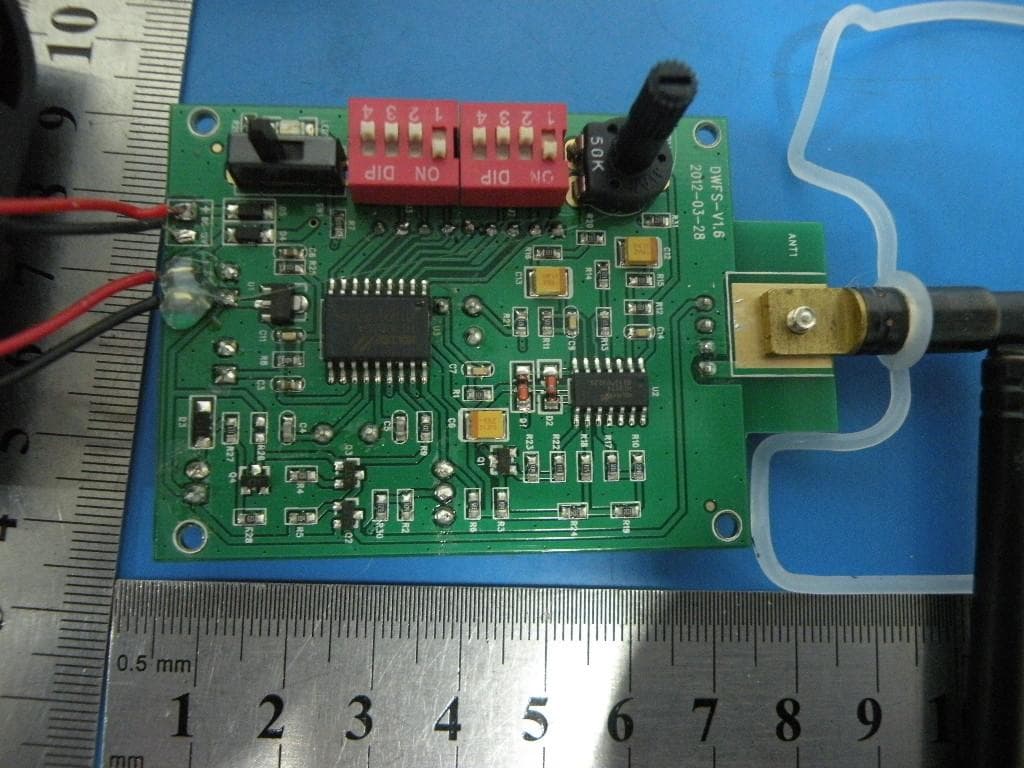
EEX-WRLB
Sep 11, 2013Monitoring System
Equipment Class
DSC - Part 15 Security/Remote Control Transmitter
EEX-FL-8
Sep 05, 2013Camera
Equipment Class
DSC - Part 15 Security/Remote Control Transmitter
EEX-TINY-W3
Sep 02, 2013TINY Camera
Equipment Class
DSC - Part 15 Security/Remote Control Transmitter