EEX-LIVECAMERALIVE CAMERA
G.G.Telecom
Click to zoom
Application Details
- Equipment Class
- JBP - Part 15 Class B Computing Device Peripheral
- Date of Grant
- Mar 26, 2012
- Application Purpose
- Original Equipment
- Date of Application
- Mar 26, 2012
- Equipment Note
- LIVE CAMERA
- Company
- G.G.Telecom
- Country
- Canada
Documents & Files
Document Text
Text extracted from the exhibit documents filed with the FCC. Open a document above to read the original.
Users Manual
Cellular Camera Caméra Cellulaire LIVE model / Modèle LIVE User’s manual / Manuel de l’utilisateur WWW.SPYPOINT.COM 3 English v2.1 ENGLISH Thank you for choosing the SPYPOINT LIVE monitoring system. This manual will help you get the most out of your new device. For the latest version of the user’s manual or for additional information, visit our website at www.spypoint.com. If you need information or to subscribe to mySPYPOINT service, go to www.myspypoint.com. 4 5 English English SPECIFICATIONS Photo recording: Photo resolution5 MP File formatJPG Multi-shotUp to 6 pictures per detection Time LapsePredefined intervals from 15sec to 2h StampDate, time, temperature and moon phase printed on photo Capture modeColor by day, black and white by night Video recording: Video resolution640 x 480 File formatMP4 Sequence lengthAdjustable from 10 to 90sec Capture modeColor by day, black and white by night Memory storage: SD/SDHC card up to 32 GB (No internal memory) Viewing: Built-in screen3.5" TFT-LCD TV outputComposite video (PAL/NTSC) Computer outputUSB 2.0 Power supply: (accessories sold separately, see “Options”) Alkaline or lithium batteries 8x AA Lithium battery packRechargeable battery pack (LIT-09) External (12V jack)12 volt battery (KIT-12V) / 12 volt adapter (AD-12V) Solar panel (12V jack)Solar panel (SP-12V) combined with rechargeable battery pack (LIT-09) Detection system: Motion sensorPIR Detection angle30° Detection rangeAdjustable from 5 to 50ft Delay between each detection Adjustable from 1 to 30min Electricity option (Connected to a 12V DC Main source only) Instant trigger time Night time illumination system: Infrared LED48 infrared LED (36 standard + 12 oversized) ExposureAutomatic infrared level adjustment Optical field of view: 50° Cellular transmission system: mySPYPOINT subscription required. For more information, visit www.myspypoint.com Photo transmissionWireless photo transmission via mySPYPOINT website Camera configurationFully configurable remotely through mySPYPOINT website KIT INCLUDES • SPYPOINT LIVE camera • GSM/GPRS cellular antenna • Strap • USB cable • Composite video cable • User manual 6 7 English English INSTALLING THE SIM CARD Insert your SIM card into the compartment provided for this purpose in your SPYPOINT LIVE camera. The SIM card compartment is located under the batteries. You need to use a Phillips screwdriver to open and close the compartment. 1. Unscrew the cover screw using a Phillips screwdriver. 2. Slide the metal bracket in the OPEN position. 3. Lift up the metal bracket. 4. Insert the SIM card as indicated. 5. Lower the metal bracket and slide it to the LOCK position . 6. Close the compartment cover. POWER SUPPLY The battery level is shown in the upper left corner of the screen when the camera is in “Test” mode. When a single line remains, the camera will continue to take pictures but we strongly recommend changing the batteries before they are empty (see figure below). AA BATTERIES This camera requires the use of 8 AA batteries (1.5V). The use of alkaline or lithium batteries is strongly recommended. Also note that the voltage of rechargeable AA batteries (1.2V) is insufficient to power this camera. During the installation of AA batteries, place the switch inside the battery case to “ALK” (i.e. alkaline). Insert the batteries in the camera as indicated. Exact polarity must be followed. We also recommend the use of new batteries to ensure maximum performance of your camera. LITHIUM BATTERY PACK The camera can be powered by a rechargeable lithium battery pack LIT-09 (sold separately, see “Options”). This type of battery is less affected by cold temperatures and lasts up to 3 times longer than alkaline batteries. During the installation of lithium batteries, place the switch inside the battery case to “RECH” (i.e. rechargeable). Insert the batteries in the camera as indicated (see figure below). ALK RECH 8 9 English English EXTERNAL The camera can be powered from an external 12 volt DC input such as a 12 volt battery (KIT-12V, sold separately) or a 12 volt adapter (AD-12V, sold separately). When using a 12 volt connection, we recommend removing the AA batteries to prevent surcharges. During the installation of a 12 volt connection, place the switch inside the battery case to “ALK” (i.e. alkaline). If combined with a lithium battery pack, slide the switch to “RECH” (i.e. rechargeable). To find the accessories available for the 12 volt power supply, see “Options”. SOLAR PANEL This model offers the possibility of a connection to a solar panel SP- 12V (sold separately, see “Options”) to maintain the charge of the lithium battery pack LIT-09 (sold separately, see “Options”). During the installation of the rechargeable lithium battery pack, slide the switch inside the battery case to “RECH” (i.e. rechargeable) to activate the charging system of the solar panel. MEMORY STORAGE Using a memory card (sold separately, see “Options”) is required to operate the camera. When the “Photo” or “Video” mode is selected, the screen displays “No memory card” if no memory card is present. The camera is compatible with SD/SDHC memory card, up to 32 GB capacity. Before inserting or removing a memory card, the camera must be turned off. Failing to do so may cause loss of pictures or damage the pictures already recorded on the memory card. When the SD card is full, the viewing screen indicates “Memory card full” when the “Photo” or “Video” mode is selected. The used space on the memory card is displayed as percentage in the upper right corner of the screen when the camera is in “Test” mode. The following data shows the approximate quantity of photos or video length that can be taken by the camera depending on the memory card capacity. 2.0 GB4.0 GB8.0 GB32 GB Photo 5 MP11902380476019040 Video 640 x 4803h5h11h43h MAIN MENU Use the “UP” and “DOWN” button to navigate the interface or to modify a selection, the “OK” button to select and the “BACK” button to return to the previous …
Text truncated - open the document above for the full version.
ID Label/Location Info
FCC Certification Label Label Location on EUT EUT View/ FCC ID Label Location FCC ID: EEX-LIVECAMERA
Internal Photos
GSM Antenna Reverse Polarity (RP-SMA) Connectors
Test Report
FCC PART 15 CLASS B EMI MEASUREMENT AND TEST REPORT For G.G.Telecom 120 Rue J-Aurele-Roux, Victoriaville, Quebec, G6T 0N5 Canada FCC ID: EEX-LIVECAMERA March 19, 2012 This Report Concerns: Original Report Equipment Type: Live Camera Test Engineer: Jack Liu Report No.: BST11120047Y-1ER-3-2 Receive EUT Date/Test Date: March 3, 2012/ March 4-16, 2012 Reviewed By: Christina Prepared By: Shenzhen BST Technology Co.,Ltd. 3F,Weames Technology Building, No. 10 Kefa Road,Science Park, Nanshan District,Shenzhen,Guangdong,China Tel: 0755-267477513 Fax: 0755-267477513 ext.826 Note: The test report is specially limited to the above company and this particular sample only. It may not be duplicated without prior written consent of Shenzhen BST Technology Co.,Ltd. This report must not be used by the client to claim product certification,approval,or endorsement by NVLAP, NIST or any agency of the US Government. TABLE OF CONTENTS G.G.Telecom FCC ID: EEX-LIVECAMERA BST FCC ID REPORT: BST11120047Y-1ER-3-2 Page 2/23 1. GENERAL INFORMATION .................................................................................................... 3 1.1. Report information............................................................................................................ 3 1.2. Measurement Uncertainty................................................................................................. 3 2. PRODUCT DESCRIPTION ...................................................................................................... 4 2.1. EUT Description ............................................................................................................... 4 2.2. Block Diagram of EUT Configuration ............................................................................. 5 2.3. Support Equipment List .................................................................................................... 6 2.4. Test Conditions .................................................................................................................6 3. FCC ID LABEL........................................................................................................................... 7 4. TEST RESULTS SUMMARY ................................................................................................... 8 Modifications ................................................................................................................................ 8 5. TEST EQUIPMENT USED ....................................................................................................... 9 6. CONDUCTED EMISSION TEST........................................................................................... 10 6.1. Block Diagram of Test Setup.......................................................................................... 10 6.2. Test Standard ..................................................................................................................11 6.3. Conducted Emission Limit(Class B) .............................................................................. 11 6.4. EUT Configuration on Test ............................................................................................ 11 6.5. Operating Condition of EUT .......................................................................................... 12 6.6. Test Procedure ................................................................................................................ 12 6.7. Test Result ...................................................................................................................... 12 7. RADIATED EMISSION MEASUREMENT ......................................................................... 17 7.1. Block Diagram of EUT Configuration ........................................................................... 17 7.2. Test Standard ..................................................................................................................18 7.3. Radiated Emission Limit(Class B) ................................................................................. 18 7.4. EUT Configuration on Test ............................................................................................ 18 7.5. Operating Condition of EUT .......................................................................................... 19 7.6. Test Procedure ................................................................................................................ 19 7.7. Test Result ...................................................................................................................... 19 G.G.Telecom FCC ID: EEX-LIVECAMERA BST FCC ID REPORT: BST11120047Y-1ER-3-2 Page 3/23 1. GENERAL INFORMATION 1.1. Report information 1.1.1.This report is not a certificate of quality; it only applies to the sample of the specific product/equipment given at the time of its testing. The results are not used to indicate or imply that they are application to the similar items. In addition, such results must not be used to indicate or imply that BST approves recommends or endorses the manufacture, supplier or use of such product/equipment, or that BST in any way guarantees the later performance of the product/equipment. 1.1.2.The sample/s mentioned in this report is/are supplied by Applicant, BST therefore assumes no responsibility for the accuracy of information on the brand name, model number, origin of manufacture or any information supplied. Additional copies of the report are available to the Applicant at an additional fee. No third part can obtain a copy of this report through BST, unless the applicant has authorized BST in writing to do so. Test Facility - The test site used to collect the radiated data is located on the address of SinTek Laboratory Co.,Ltd. (FCC Registered Test Site Number: 963441) on No.7, Xinshidai Industrial, Guantian Village, Shiyan Town, Baoan District, Shenzhen, Guangdong 518108, China The Test Site is constructed a…
Text truncated - open the document above for the full version.
Test Setup Photos
Radiated emissions test Conducted emissions test
Contact Information
Applicant
Yan Gagnon(President)
Test Firm
SinTek Laboratory Co., Ltd.Eric Lin
Technical Specifications
| # | Rule Parts | Frequency Range | Power Output |
|---|---|---|---|
| 1 | 15B | - | - |
Other Applications from G.G.Telecom

EEX-MLIVE
Jun 30, 2015Surveillance Camera
Equipment Class
PCB - PCS Licensed Transmitter
EEX-MINI-LIVE
Oct 13, 2014Surveillance Camera
Equipment Class
PCB - PCS Licensed Transmitter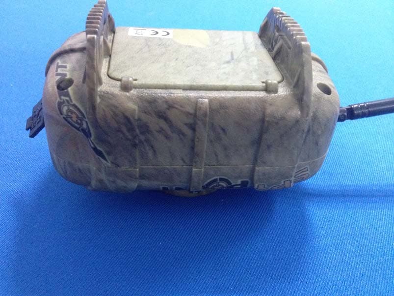
EEX-MS-1
Nov 19, 2013WIRELESS MOTION SENSOR
Equipment Class
DSC - Part 15 Security/Remote Control Transmitter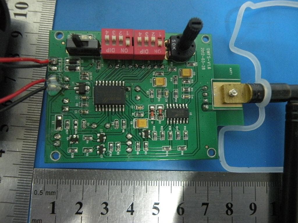
EEX-WRLB
Sep 11, 2013Monitoring System
Equipment Class
DSC - Part 15 Security/Remote Control Transmitter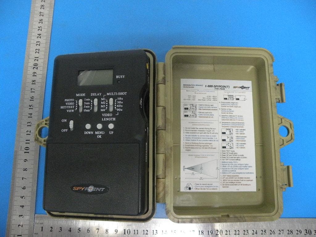
EEX-FL-8
Sep 05, 2013Camera
Equipment Class
DSC - Part 15 Security/Remote Control Transmitter