EEX-WRLMonitoring System
G.G.Telecom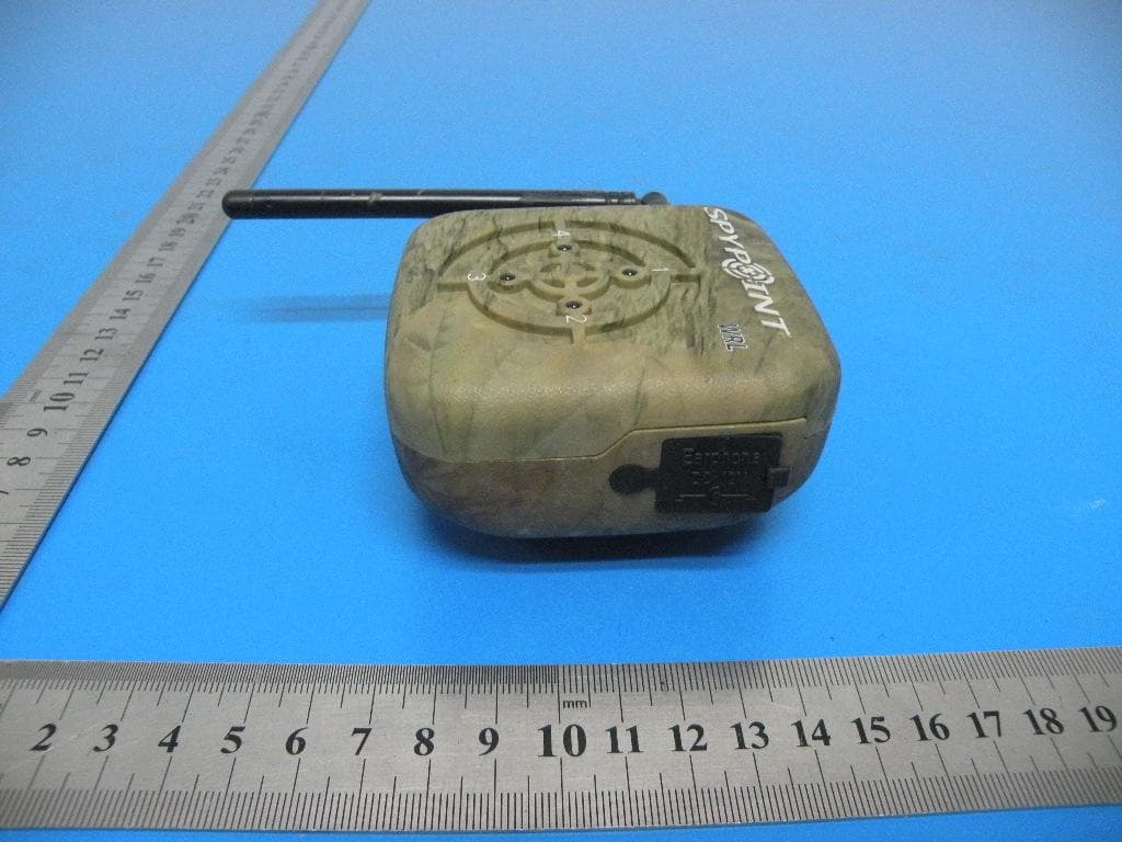
Click to zoom
Application Details
- Equipment Class
- CYY - Communications Receiver used w/Pt 15 Transmitter
- Date of Grant
- Aug 06, 2013
- Application Purpose
- Original Equipment
- Date of Application
- Aug 06, 2013
- Equipment Note
- Monitoring System
- Frequency Range
- 433.92000000 - 433.92000000
- Company
- G.G.Telecom
- Country
- Canada
Documents & Files
Document Text
Text extracted from the exhibit documents filed with the FCC. Open a document above to read the original.
Users Manual
G.G. TELECOM Victoriaville, Québec - Canada, G6T 0N5 Téléphone : 514-868-1811 Sans frais : 1-888-SPYPOINT Swanton, Vermont - USA Tel.: 1-888-SPYPOINT 1-888-779-7646 www.spypoint.com PINTSPY TM INTPSPY Le SPYPOINT WRL est un système de détection de mouvement sans fil. Cet appareil permet de détecter n’importe quelle source de chaleur en mouvement. Suite à une détection, un signal sans fil d’une portée maximale de 1000 pieds sera transmis au récepteur qui vibrera et identifiera, par un témoin lumineux, le détecteur qui a réagi à un mouvement. Le SPYPOINT WRL est principalement utilisé par les chasseurs pour les informer de l’approche de leur gibier. De plus, l’appareil est aussi utilisé dans le domaine de la surveillance résidentielle et commerciale. ALIMENTATION Le système est alimenté par 2 piles 9 volts (une pour le récepteur et une pour le détecteur). Pour installer une pile dans le récepteur, tourner premièrement la clips de ceinture et tirer sur la porte de pile vers le haut. Insérer la pile en respectant les symboles de polarité (+ et -). Lorsqu’une pile est faible, le témoin lumineux bleu du récepteur clignotera lors d’une détection pour indiquer que la pile devra être changée sous peu. Sinon, en temps normal, le témoin lumineux reste allumé durant environ 10 secondes pour que l’utilisateur puisse avoir assez de temps pour vérifier la provenance de la détection. Dès qu’un appareil cesse de fonctionner normalement, remplacer la pile. La pile du détecteur peut durer jusqu’à 30 jours sans mettre l’appareil à OFF. Dans le récepteur, la pile durera environ 4 jours puisque celui-ci est toujours en attente d’un signal. Il est donc recommandé de le mettre à OFF lorsqu’il n’est pas utilisé. UTILISATION Le bouton «detector» permet de choisir le numéro d’identification de chaque détecteur. L’ensemble WRL inclut 1 détecteur qui devra être configuré selon le choix de l’utilisateur. Le récepteur peut accepter jusqu’à 4 détecteurs. Chaque détecteur additionnel (modèle WRL-B vendu séparément) devra être configuré avec son propre numéro d’identification pour le distinguer des autres. Pour régler le numéro d’un détecteur, glisser vers le haut l’un des quatre sélecteurs. (voir exemple à l’intérieur de la porte de pile) Le bouton «channel» permet de choisir une des quatre fréquences différentes de la transmission sans fil. Cette option permet à 4 utilisateurs différents d’être dans le même périmètre de surveillance sans aucune interférence. Pour régler la fréquence voulue, glisser vers le haut l’un des quatre sélecteurs. (voir exemple à l’intérieur de la porte de pile). Le récepteur et les détecteurs d’un même ensemble doivent être configurés à la même fréquence. Lorsque l’appareil est mis à ON, l’utilisateur doit attendre 30 secondes avant que le détecteur puisse débuter la détection pour lui permettre de s’initialiser. Le bouton «distance» permet de régler la sensibilité du détecteur. Pour augmenter la sensibilité, tourner le bouton vers la droite. Pour la diminuer, tourner vers la gauche. La distance maximale de détection d’une cible en mouvement est d’environ 40 pieds. Pour mettre le système en fonction, placer le sélecteur ON/OFF en position «ON». Pour le mettre hors tension, placer le sélecteur en position «OFF». RECOMMANDATIONS • Installer les détecteurs à environ 4 pieds du sol (pour utilisation à la chasse). • Lors du remisage de l’appareil pendant plus de 30 jours, retirer les piles du système. • Installer les détecteurs sur une surface fixe. CARACTÉRISTIQUES • La distance maximale pour le transfert entre un détecteur et un récepteur est d’environ 1000 pieds. • Selon la hauteur de l’installation, la distance maximale de détection est d’environ 40 pieds. • Le détecteur possède un angle de détection de 30º degrés. • La température de fonctionnement du système varie de -20ºC (4ºF) à +60ºC (140ºF). GARANTIE G.G. Telecom garantit ce produit contre tout vice de matériau ou de fabrication pour une période de 1 an à compter de la date d’achat. Toute modification apportée aux composantes internes du système peut provoquer des défectuosités et entraîner l’annulation de la garantie. G.G. TELECOM Victoriaville, Québec - Canada, G6T 0N5 Tel. : 514-868-1811 Toll-free : 1-888-SPYPOINT Swanton, Vermont - USA Tel.: 1-888-SPYPOINT 1-888-779-7646 www.spypoint.com PINTSPY TM INTPSPY SPYPOINT WRL is a wireless motion detection system which detects all moving heat sources. A detected movement will send a wireless signal at an approx. distance of 1000 ft, to a vibrating receiver giving the detector’s emplacement. Used primarily by game hunters, SPYPOINT WRL warns of an animal’s presence. Moreover, this instrument is also used extensively in the field of commercial and residential surveillance. POWER The system is powered by 2-9v batteries (1 for detector, 1 for receiver). To install batteries in the receiver, turn belt clip and pull battery cover upwards. Insert batteries according to their proper polarity as indicated (+ and -). When battery load is low, the receiver’s blue light will blink when detection occurs to warn the user to change the battery soon. The battery life in the detectors is around 30 days and around 4 days for the receiver because the receiver is always waiting for a signal. We suggest to turn OFF the receiver when it is not used. USE The “detector” knob allows the choice of each detector’s ID number. A WRL kit includes 1 detector which will have to be determined according to the user’s choice. A receiver can take up to 4 detectors. Each additional detector (model WRL-B sold separately) will have to be identified according to its own ID number in order to differentiate it from other detectors. To set ID number, only push upwards one of the 4 selectors (see example inside battery door). The “channel” knob allows the choice of wireless frequency. This option allows 4 different persons to be in the same surveillance perimeter, without any interference. To set channel, push upwards one of the 4 sel…
Text truncated - open the document above for the full version.
Cover Letter(s)
G.G.Telecom SCS-F18: Project and Product Certification Representative Authorization Letter Page 1 of 2 Rev 3.0 775 Montague Expressway Milpitas, CA 95035 Tel: 408-526-1188 Fax: 408-526-1088 Email: [email protected] Project and Product Certification Representative Authorization Letter Reason for Amendment (current / obsolete) Revision History Approved Date From To Initial Release (obsolete) 1.0 1.0 Nov-14-2006 Revised wording (obsolete) 1.0 2.0 Sept–25-2007 Updated company template (current) 2.0 3.0 Jan-31-2012 G.G.Telecom SCS-F18: Project and Product Certification Representative Authorization Letter Page 2 of 2 Rev 3.0 2013/7/22 To: SIEMIC, INC. 775 Montague Expressway, Milpitas, CA 95035 USA Dear Sir/Madam, Re: Project and Product Certification Representative Authorization Letter We, G.G.Telecom hereby authorize SIEMIC, INC. to act as a Certification Body for certifying for the following project(s): Product: Monitoring System Model Name: WRL-L Trade Name: SPYPOINT FCC ID: EEX-WRL We affirm that between SIEMIC and ___ G.G.Telecom __, any difference in understanding, including test plan, measurement methods, applicable standards and relevant procedures and processes have been resolved prior to commencement of testing activities. Sincerely, Client’s signature Signature Date:2013/7/22 Name: Yan Gagnon Title: President Tel: 514 868 1811 Company: G.G.Telecom
Cover Letter(s)
G.G.Telecom SCS-F19: Confidentiality Request Letter Page 1 of 2 Rev 3.0 775 Montague Expressway Milpitas, CA 95035 Tel: 408-526-1188 Fax: 408-526-1088 Email: [email protected] Confidentiality Request Letter Reason for Amendment (current / obsolete) Revision History Approved Date From To Initial Release (obsolete) 1.0 1.0 Nov-14-2006 Adding CFR 2.459 (obsolete) 1.0 2.0 August – 11 - 2008 Updated company template & Added text box (current) 2.0 3.0 Jan-31-2012 G.G.Telecom SCS-F19: Confidentiality Request Letter Page 2 of 2 Rev 3.0 2013/7/22 To: Federal Communications Commission Authorization and Evaluation Division 7435 Oakland Mills Road Columbia, MD Subject: Permanent Confidentiality Request for FCC ID: EEX-WRL We hereby request confidential treatment of information accompanying this application as outlined below: - Block Diagram - Schematics - Operational Description The above materials contain trade secrets and proprietary information not customarily released to the public. The public disclosure of these materials may be harmful to the applicant and provide unjustified benefits to its competitors. The applicant understands that pursuant to Section 0.457 & 0.459 of the Rules, disclosure of this application and all accompanying documentation will not be made before the date of the Grant for this application. Sincerely, Client’s signature Signature Date:2013/7/22 Name: Yan Gagnon Title: President Tel: 514 868 1811 Company: G.G.Telecom
External Photos
EUT View EUT View EUT View EUT View EUT View EUT View EUT View EUT View
ID Label/Location Info
Label: Label Location FCC ID: EEX-WRL This device complies with Part 15 of the FCC Rules. Operation is subject to the following two conditions: (1) this device may not cause harmful interference, and (2) this device must accept any interference received, including interference that may cause undesired operation.
Internal Photos
Top View Top View Bottom View Top View Antenna Bottom View
Test Report
FCC TEST REPORT FCC ID: EEX-WRL Product: Monitoring System Trade Name: SPYPOINT Model Number: WRL-L Report No.: NTEK-2013NT0705025F Prepared for G.G.Telecom 120 Rue J-Aurele-Roux, Victoriaville, Quebec G6T 0N5,Canada Prepared by Shenzhen NTEK Testing Technology Co., Ltd. 1/F, Building E, Fenda Science Park, Sanwei Community, Xixiang Street, Bao’an District, Shenzhen P.R. China Tel.: +86-0755-61156588 Fax.: +86-0755-61156599 Website: www.ntek.org.cn Page 2 of 21 Report No.: NTEK-2013NT0705025F TEST RESULT CERTIFICATION Applicant’s name ................. : G.G.Telecom Address ................................. : 120 Rue J-Aurele-Roux, Victoriaville, Quebec G6T 0N5,Canada Manufacturer's Name .......... : G.G.Telecom Address ................................. : 120 Rue J-Aurele-Roux, Victoriaville, Quebec G6T 0N5,Canada Product description Product name............................ : Monitoring System Model and/or type reference : WRL-L Standards ............................. : FCC Part15B:2013 ANSI C63.4:2003 This device described above has been tested by NTEK, and the test results show that the equipment under test (EUT) is in compliance with Part 15 of FCC Rules. And it is applicable only to the tested sample identified in the report. This report shall not be reproduced except in full, without the written approval of NTEK, this document may be altered or revised by NTEK, personal only, and shall be noted in the revision of the document. Date of Test ........................................... : Date (s) of performance of tests ............. : 05 July. 2013 ~11 July. 2013 Date of Issue .......................................... : 12 July. 2013 Test Result.............................................. : Pass Testing Engineer : (Apple Huang) Technical Manager : (Jim He) Authorized Signatory : (Bovey Yang) Page 3 of 21 Report No.: NTEK-2013NT0705025F Table of Contents Page 1 . TEST SUMMARY 4 1.1 TEST FACILITY 5 1.2 MEASUREMENT UNCERTAINTY 5 2 . GENERAL INFORMATION 6 2.1 GENERAL DESCRIPTION OF EUT 6 2.2 DESCRIPTION OF TEST MODES 7 2.3 DESCRIPTION OF TEST SETUP 8 2.4 DESCRIPTION TEST PERIPHERAL AND EUT PERIPHERAL 9 2.5 MEASUREMENT INSTRUMENTS LIST 10 3 . EMC EMISSION TEST 11 3.1 CONDUCTED EMISSION MEASUREMENT 11 3.1.1 POWER LINE CONDUCTED EMISSION 11 3.1.2 TEST PROCEDURE 12 3.1.3 TEST SETUP 12 3.1.4 EUT OPERATING CONDITIONS 12 3.1.5 TEST RESULTS 13 3.2 RADIATED EMISSION MEASUREMENT 15 3.2.1 LIMITS OF RADIATED EMISSION MEASUREMENT 15 3.2.2 TEST PROCEDURE 15 3.2.3 TEST SETUP 16 3.2.4 EUT OPERATING CONDITIONS 16 3.2.5 TEST RESULTS 17 3.2.6 TEST RESULTS(Above 1GHz) 19 4 . EUT TEST PHOTO 20 Page 4 of 21 Report No.: NTEK-2013NT0705025F 1. TEST SUMMARY Test procedures according to the technical standards: EMC Emission Standard Test Item Limit Judgment Remark FCC Part15B:2013 ANSI C63.4: 2003 Conducted Emission Class B PASS Radiated Emission Class B PASS NOTE: (1) ’N/A’ denotes test is not applicable in this Test Report (2) For client’s request and manual description, the test will not be executed. Page 5 of 21 Report No.: NTEK-2013NT0705025F 1.1 TEST FACILITY NTEK Testing Technology Co., Ltd Add. : 1/F, Building E, Fenda Science Park, Sanwei Community, Xixiang Street, Bao’an District, Shenzhen P.R. China. FCC Registered No.: 238937 IC Registered No.:9270A-1 CNAS Registration No.:L5516 1.2 MEASUREMENT UNCERTAINTY The reported uncertainty of measurement y ± U,where expended uncertainty U is based on a standard uncertainty multiplied by a coverage factor of k=2,providing a level of confidence of approximately 95 %. A. Conducted Measurement : Test Site Method Measurement Frequency Range U,(dB) NOTE NTEKC01 ANSI 150 KHz ~ 30MHz 3.2 B. Radiated Measurement : Test Site Method Measurement Frequency Range U,(dB) NOTE NTEKA01 ANSI 30MHz ~ 1000MHz 4.7 1GHz ~6GHz 5.0 Page 6 of 21 Report No.: NTEK-2013NT0705025F 2. GENERAL INFORMATION 2.1 GENERAL DESCRIPTION OF EUT Equipment Monitoring System Model Name WRL-L Serial No N/A Model Difference N/A Product Description The EUT is a Monitoring System . Operating frequency: 433.92MHz Connecting I/O port: N/A Based on the application, features, or specification exhibited in User's Manual, More details of EUT technical specification, please refer to the User's Manual. Power Source DC Voltage Power Rating DC 12V from adapter with AC 120V/60Hz Page 7 of 21 Report No.: NTEK-2013NT0705025F 2.2 DESCRIPTION OF TEST MODES To investigate the maximum EMI emission characteristics generates from EUT, the test system was pre-scanning tested base on the consideration of following EUT operation mode or test configuration mode which possible have effect on EMI emission level. Each of these EUT operation mode(s) or test configuration mode(s) mentioned above was evaluated respectively. Pretest Mode Description Mode 1 RX For Conducted Test Final Test Mode Description Mode 1 RX For Radiated Test Final Test Mode Description Mode 1 RX Page 8 of 21 Report No.: NTEK-2013NT0705025F 2.3 DESCRIPTION OF TEST SETUP E-1 EUT E-2 Adapter Page 9 of 21 Report No.: NTEK-2013NT0705025F 2.4 DESCRIPTION TEST PERIPHERAL AND EUT PERIPHERAL The EUT has been tested as an independent unit together with other necessary accessories or support units. The following support units or accessories were used to form a representative test configuration during the tests. Item Equipment Mfr/Brand Model/Type No. Series No. Note E-1 Monitoring System N/A WRL-L N/A EUT E-2 Adapter N/A TLP-12 N/A Item Shielded Type Ferrite Core Length Note / NO NO / Note: (1) The support equipment was authorized by Declaration of Confirmation. (2) For detachable type I/O cable should be specified the length in cm in『Length』column. (3) “YES” means “shielded” “with core”; “NO” means “unshielded” “without core”. Page 10 of 21 Report No.: NTEK-2013NT0705025F 2.5 MEASUREMENT INSTRUMENTS LIST 2.5.1 CONDUCTED TEST SITE Item Kind of Equipment Manufacturer Type No. Serial No. Calibrated until 1 LISN R&S ENV216 101313 Jul. 06, 2013 2 LISN EMCO 3816/2 00042990 J…
Text truncated - open the document above for the full version.
Test Setup Photos
Radiated Emission Test Setup in Chamber Conducted Emission Test Setup
Contact Information
Applicant
Yan Gagnon(President)
Test Firm
NTEK Testing Technology Co., Ltd.Wetow Huang
Technical Specifications
| # | Rule Parts | Frequency Range | Power Output |
|---|---|---|---|
| 1 | 15B | 433.92 MHz - 433.92 MHz | - |
Other Applications from G.G.Telecom

EEX-MLIVE
Jun 30, 2015Surveillance Camera
Equipment Class
PCB - PCS Licensed Transmitter
EEX-MINI-LIVE
Oct 13, 2014Surveillance Camera
Equipment Class
PCB - PCS Licensed Transmitter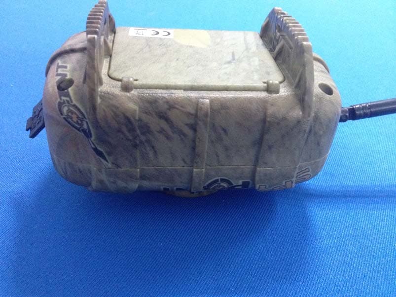
EEX-MS-1
Nov 19, 2013WIRELESS MOTION SENSOR
Equipment Class
DSC - Part 15 Security/Remote Control Transmitter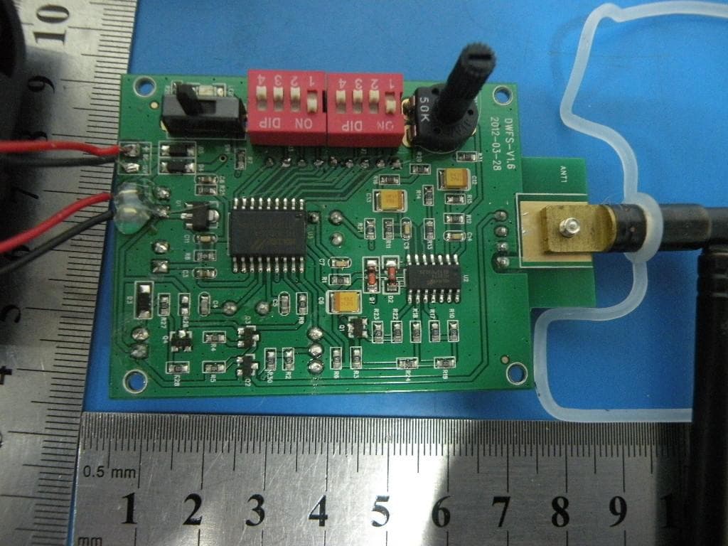
EEX-WRLB
Sep 11, 2013Monitoring System
Equipment Class
DSC - Part 15 Security/Remote Control Transmitter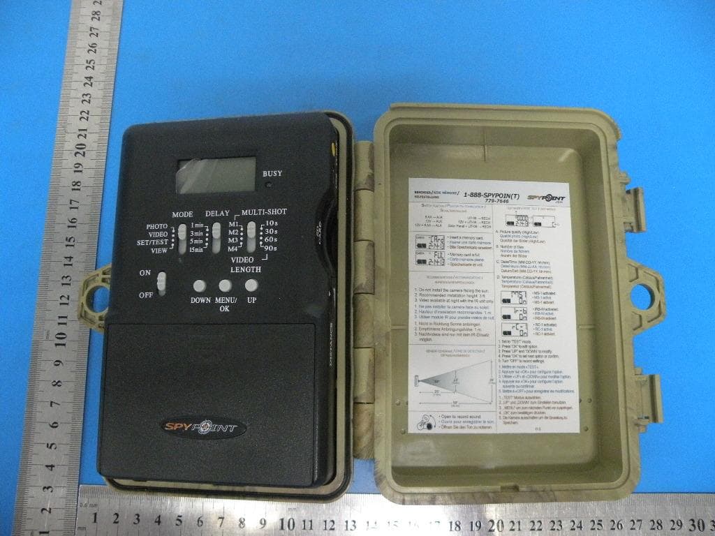
EEX-FL-8
Sep 05, 2013Camera
Equipment Class
DSC - Part 15 Security/Remote Control Transmitter