EHA-BTM4BTM4
Intermec Technologies Corporation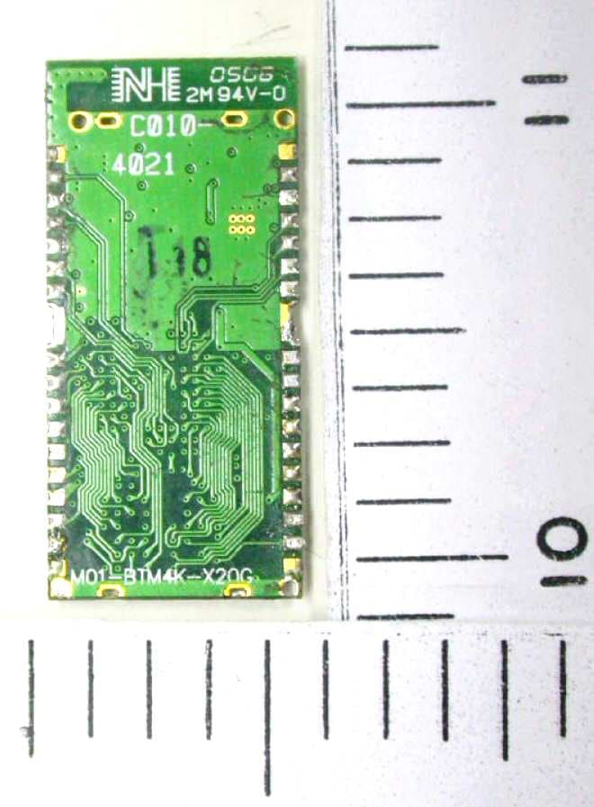
Click to zoom
Application Details
- Equipment Class
- DTS - Digital Transmission System
- Date of Grant
- Mar 11, 2008
- Application Purpose
- Original Equipment
- Date of Application
- Mar 11, 2008
- Equipment Note
- BTM4
- Frequency Range
- 2402.00000000 - 2480.00000000
- Country
- United States
Documents & Files
Document Text
Text extracted from the exhibit documents filed with the FCC. Open a document above to read the original.
Users Manual
IP30 Compliance Insert Note: This equipment may be used on an IT power system. For Users in the United States and Canada The users of this product are cautioned to use accessories and peripherals approved by Intermec Technologies Corporation. The use of accessories other than those recommended, or changes to this product that are not approved by Intermec Technologies Corporation, may void the compliance of this product and may result in the loss of the user’s authority to operate the equipment. Utilisateurs de ce produit sont avisés d’utiliser des accessoires et des périphériques approuvés par Intermec Technologies Corporation. L’utilisation d’accessoires autres que ceux recommandés ou des changements à ce produit qui ne sont pas approuvés par Intermec Technologies Corporation peuvent annuler la conformité de ce produit et mettre fin au droit qu’a l’usager d’utiliser l’équipement. FCC Digital Emissions Compliance This equipment has been tested and found to comply with the limits for a Class B digital device, pursuant to Part 15 of the FCC Rules. These limits are designed to provide reasonable protection against harmful interference in a residential installation. This equipment generates uses and can radiate radio frequency energy and, if not installed and used in accordance with the instructions, may cause harmful interference to radio communications. However, there is no guarantee that interference will not occur in a particular installation. If this equipment does cause harmful interference to radio or television reception, which can be determined by turning the equipment off and on, the user is encouraged to try to correct the interference by one or more of the following measures: •Reorient or relocate the radio or television receiving antenna. •Increase the separation between the computer equipment and receiver. •Connect the equipment into an outlet on a circuit different from that to which the radio or television receiver is connected. •Consult the dealer or an experienced radio television technician for help. Canadian Digital Apparatus Compliance This Class B digital apparatus meets all requirements of the Canadian Interference-Causing Equipment Regulations. Conformité aux normes canadiennes sur les appareils numériques Cet appareil numérique de la classe B respecte toutes les exigences du Réglement sur le matériel brouilleur du Canada. Caution: This marking indicates that the user should read all included documentation before use. Attention: Ce marquage indique que l’usager doit, avant l’utilisation, lire toute la documentation incluse. Caution: For use with Intermec battery pack Model 074201 only. For power supply, use Intermec Model 073573. No user- serviceable parts. Attention: Pour utilisation seulement avec bloc-batterie Intermec modèle 074201. Pour la source d’alimentation, utilisez Intermec modèle 073573. Il ne contient aucune pièce réparable par l’utilisateur. Battery Information Battery Recycling Information Note: In the U.S.A., the EPA does not consider spent Li-ion batteries as hazardous waste. Maximum Permissive Exposure (MPE) Radio Wave or Radio Frequency Maximum Permissive Exposure (MPE) Information for Model IP30 RFID Reader When Installing and using the Intermec IP30 RFID Reader, a 23 cm (9 in.) (or greater distance per MPE calculation) passing distance must be maintained from any body part of the user or nearby persons and the IP30 antenna. The antenna must not be touched during transmitter operation. Important Radio Information! This device complies with Part 15 of the FCC rules and with RSS-210 of Industry Canada. Operation is subject to the following two conditions: (1) This device may not cause harmful interference, and (2) This device must accept any interference received, including interference that can cause undesired operation. Caution: The battery pack used in this device may ignite, create a chemical burn hazard, explode, or release toxic materials if mistreated. Do not incinerate, disassemble, or heat above 100 °C (212°F). Charge only with Intermec Models AC6, AC7, and AC8. Do not short circuit; may cause burns. Keep away from children. Use only Intermec battery pack Model AB3. Use of incorrect battery pack may present risk of fire or explosion. Promptly dispose of used battery pack according to the instructions. Attention: Le bloc-piles utilisé dans cet appareil peut prendre feu, constituer un risque de brûlure chimique, exploser ou dégager des substances toxiques s’il est manipulé de façon inappropriée. Ne pas jeter au feu, démonter ou chauffer à plus de 100 °C (212 °F). Ne charger qu’avec les dispositifs Intermec AC6 et AC7. Ne pas court-circuiter; cela pourrait causer des brûlures. Garder hors de la portée des enfants. N’utiliser que le modèle de bloc-piles Intermec AB3. L’utilisation d’un mauvais bloc-piles pourrait constituer un risque d’incendie ou d’explosion. Mettre rapidement au rebut tout bloc-piles usé, conformément aux instructions. Li-ionLi-ion This product contains or uses a lithium-ion (Li-ion) main battery. When the battery reaches the end of its useful life, the spent battery should be disposed of by a qualified recycler or hazardous materials handler. Do not mix this battery with the solid waste stream. Contact your Intermec Technologies Service Center for recycling or disposal information. Ce produit contient ou utilise une pile principale au lithium-ion (Li-ion). Lorsque la batterie atteint la fin de sa durée de vie utile, la batterie usées doivent être mises aux rebuts par un agent de recyclage ou un manipulateur de matériaux dangereux agréé. Il ne faut pas mélanger la batterie aux autres déchets solides. Pour plus d’informations sur le recyclage ou la mise aux rebuts, contacter votre centre de services Intermec Technologies. Caution: Changes or modifications not expressly approved by Intermec could void the user’s authority to operate this equipment. For Users Outside of the United States or Canada Battery Information Battery Recy…
Text truncated - open the document above for the full version.
Users Manual
IP4 Portable RFID Reader Instructions iiIP4 Portable RFID Reader Instructions Contents Introducing the IP4 Portable RFID Reader . . . . . . . . . . . . . 3 What You Get . . . . . . . . . . . . . . . . . . . . . . . . . . . . . . . . . . . 3 Using the IP4 . . . . . . . . . . . . . . . . . . . . . . . . . . . . . . . . . . . . 3 Charging and Installing the Battery . . . . . . . . . . . . 3 Attaching Your IP4 to a 700 Color . . . . . . . . . . . . . 5 (Optional) Configuring Your IP4 as a Keyboard Wedge . . . . . . . . . . . . . . . . . . . . . . . . 6 Reading an RFID Tag . . . . . . . . . . . . . . . . . . . . . . 8 Understanding the IP4 LEDs . . . . . . . . . . . . . . . . . . . . . . . . 9 Specifications . . . . . . . . . . . . . . . . . . . . . . . . . . . . . . . . . . . 10 IP4 Portable RFID Reader Instructions3 Introducing the IP4 Portable RFID Reader The IP4 Portable RFID Reader is an accessory handle for the 700 Series Color mobile computers. Together, the IP4 and 700 Color provide a high-performance mobile RFID solution that allows you to bring the read/write device to the tagged product rather than moving tagged products past a fixed reader. What You Get • IP4 Portable RFID Reader • Battery (Model AB12) • Product documentation Using the IP4 To use the IP4, you need to perform these steps: 1Charge and install the battery. 2Attach your IP4 to a 700 Color. 3(Optional) Configure your IP4 as a keyboard wedge. 4Read an RFID tag. These instructions describe each step. Charging and Installing the Battery To charge the IP4 battery, you need the Dual Pack Battery Charger (Model AC12). To charge the IP4 battery • Insert the battery into a slot on the AC12 battery charger. A fully discharged battery charges in less than 4 hours. 4IP4 Portable RFID Reader Instructions To install the battery 1Insert the battery tab on the top of the battery into the IP4. 2Firmly press the bottom of the battery onto the IP4 until the battery snaps into place. To remove the battery • Push the battery release latch on the bottom of the IP4. Battery tab Battery release latch IP4 Portable RFID Reader Instructions5 Attaching Your IP4 to a 700 Color Your IP4 uses Infrared Data Association (IrDA) to communicate with the 700 Color. The lightpipe in the IP4 helps communicate the IrDA signal between the 700 Color and your IP4. To attach your IP4 to a 700 Color 1Slide the 700 Color into the IP4 until it clicks into place. Note: Do not remove the lightpipe from the IP4. Lightpipe 6IP4 Portable RFID Reader Instructions 2Secure the retaining screws, making sure that they are inserted straight into the 700 Color. To remove your IP4 from a 700 Color 1Remove the two retaining screws. 2Hold the 700 Color at the display. 3While lifting the 700 Color up (away from the IP4), pull the 700 Color forward and out of the IP4. (Optional) Configuring Your IP4 as a Keyboard Wedge You can configure your IP4 as a keyboard wedge to allow the 700 Color to receive data from your IP4 as it would from a keyboard. To use your IP4 as a keyboard wedge, the 700 Color and your IP4 must meet these requirements: • The 700 Color must have at least 64MB of flash ROM. • The fifth character in the configuration number (CN) found on the back of the 700 Color must not be a 4 or 5. For example: •751B6xxxx meets this requirement. •760A4xxxx does not meet this requirement. IP4 Portable RFID Reader Instructions7 • The 700 Color must be running one of these operating systems (OS): • 4.95.1 or later Prem (Premium) • 4.96.4 or later GSM Phone • If the fourth character in the configuration number (CN) of your IP4 is an “A”: • The 700 Color must be running IVA 4.03.35.1043 or later. • Your IP4 must be running firmware version 5.19 or later. • If the fourth character in the configuration number (CN) of your IP4 is an “B”: • The 700 Color must be running IVA 4.03.35.1050 or later. • Your IP4 must be running firmware version 7.16 or later. To configure your IP4 as a keyboard wedge 1Fully charge your IP4 battery and attach your IP4 to a 700 Color. 2On the 700 Color, start Intermec Settings. 3Select RFID > Reader 1, and select Enable Reader. 4Under Reader 1, select Reader Module > Ta g Ty p e, and select the type of RFID tag you are using. 5From the main Intermec Settings menu, select Device Settings > Keypad > Scan Button Remapping > Handle Tr i g g e r, and select RFID. 6Save your settings. Note: Use Intermec Settings to find the OS and IVA versions of the 700 Color. For help, see the user’s manual for the 700 Color. 8IP4 Portable RFID Reader Instructions To test the keyboard wedge 1Start Microsoft Pocket Word. 2Read an RFID tag. For help, see the next section. The RFID tag information appears in Pocket Word. Reading an RFID Tag You can scan at least six RFID tags per second with the IP4. To read an RFID tag 1Position the front of the IP4 within 91 cm (3 ft) of an RFID tag. 2Pull the trigger. Note: Continuously reading tags with the IP4 may cause the IP4 to overheat. If the IP4 temperature rises above the maximum operating temperature, the IP4 will stop reading tags. If this occurs, let the IP4 cool down until its temperature is within the operating temperature range. RF Exposure regulations limit exposure to radio frequency (RF) radiation. To comply with these regulations, operators of this device must maintain a distance of at least 20 cm (8 in) from the cover on the antenna assembly. (The cover on the antenna is the dome-shaped surface.) While the device is on, the operator’s body and parts of the body such as eyes, hands, or head, must be 20 cm (8 in) or farther from the cover of the antenna assembly. Avertissement: Les réglementations sur les expositions RF limitent l'exposition aux rayonnements RF. Pour se conformer à ces réglementations, les opérateurs de ce dispositif doivent maintenir une distance minimale de 20 cm du couvercle de l'antenne. (Le couvercle de l'antenne est la surface bombée.) Lorsque l'appareil est sous tension, le corps et les parties du corps (ye…
Text truncated - open the document above for the full version.
Attestation Statements
Date: February 27, 2008 Telecommunication Certification Body Federal Communications Commission Certification Body Industry Canada, Certification and Engineering Bureau Subject: Modulation Limitations Bluetooth Module BTM4 To whom it may concern, The BTM4 modules integrated within Intermec devices cannot use Bluetooth EDR modulations π/4-DQPSK or 8DPSK due to Intermec system design. The system data rate maximum is 115.2 k baud. The Bluetooth UART hardware baud rate of 115.2 k and virtual machine software interface to the host or peripheral keeps data transfers well below the 1 to 3 megabit rate needed for EDR to function. Therefore the BTM4 will only transmit data at the Bluetooth™ defined “basic data rate” DH1, DH3 and DH5 using GFSK modulation. Please contact me by telephone at (319) 846-2415 or by e-mail ([email protected]) if there are questions or additional information needed concerning this request. Sincerely, Dave Fry Sr. EMC Engineer 550 Second St SE Cedar Rapids, IA 52401 Dave Fry MS GR05 Sr. EMC Engineer tel 319 846-2415 fax 319 846-2475 [email protected] www.intermec.com
Cover Letter(s)
Northwest EMC TCB Compliance Opinion Rev. 9/15/03 ITRM0173 Information about the Applicant Grantee (Company Name) Intermec Technologies Corporation FCC Contact Person Dave Fry Address 550 Second St SE City, State, Zip Cedar Rapids, IA 52401 Job Number ITRM0173 Model BTM4 Bluetooth radio FCC ID EHA-BTM4 Agent Northwest EMC, Inc. Approval Type Original Equipment Class DTS Digital Transmission System Rule Part 15.247 Overview See Client provided cover letter. Confidentiality requested for allowed files. Request is properly addressed and referenced. Recommendation All items have been resolved and completed to my satisfaction; therefore I recommend this application for approval. Signature Dean Ghizzone, TCB Committee March 9, 2008
Cover Letter(s)
Date: February 25, 2008 Telecommunication Certification Body (and/or) Federal Communications Commission Authorization and Evaluation Division 7435 Oakland Mills Road Columbia, Maryland 21046 Subject: Long Term Confidentiality FCC ID: EHA-BTM4 To whom it may concern, We hereby respectfully request that under the provisions of 47 CFR 0.457 and 0.459, the documents listed below and attached with this application for certification be provided with permanent confidential status. • Schematics • Theory of Operation • Frequency Block Diagrams Any exhibit / information for which we have requested confidentiality, but which may not be accorded such treatment by the FCC, should be returned to us. The documents contain trade secrets and proprietary information that are treated as confidential and not released to the public. Substantial competitive harm to Intermec or our suppliers could result should they be made available to the public. Please contact me by telephone at (319) 846-2415 or by e-mail ([email protected]) if there are questions or additional information needed concerning this request. Sincerely, Dave Fry Sr. EMC Engineer 550 Second St SE Cedar Rapids, IA 52401 Dave Fry MS GR05 Sr. EMC Engineer tel 319 846-2415 fax 319 846-2475 [email protected] www.intermec.com
Cover Letter(s)
Page 1 of 2 Date: February 26, 2008 Telecommunication Certification Body (and/or) Federal Communications Commission Authorization and Evaluation Division 7435 Oakland Mills Road Columbia, Maryland 21046 Subject: Application for Grant FCC ID: EHA-BTM4 Dear Application Examiner: Intermec Technologies Corporation, with the assistance of Northwest EMC Inc. is submitting this new application for certification of BTM4 Bluetooth radio, FCC ID: EHA-BTM4. This application requests approval of the BTM4 for “Limited Modular Approval” for portable RF exposure when used alone. We are also requesting approval of several collocated mobile RF exposure conditions described below. Future use of the BTM4 will involve stand-alone portable applications. The BTM4 is provided to Intermec to operate at 10 mW. The FCC rules indicate the transmitter can be used without SAR testing per the [60 / f (GHz) = low threshold (mw)] calculation 60 / 2.48 = 24.19 mW. We are requesting “Limited Modular Approval” for the BTM4 with the grant notes indicating non- collocated operation is allowed without SAR testing of the 10 mW BTM4 radio. The BTM4 will have immediate collocation for mobile RF exposure with the following transmitters. The BTM4 transmitter is placed within a new IP30, pistol grip RFID scanner. The IM4 radio is the RFID portion while the BTM4 radio provides wireless communication to the hand held computers. We are also processing a Class II Permissive Change collocation with IM4 RFID radio, FCC ID: EHAIM4. The IP30 snaps on the bottom of several Intermec hand held computers. The IP30 hand grip has a docking cradle for Intermec's CK61, CN3 and CN3e handheld computers. CK61 contains FCC ID: EHA802UIAG FCC ID: HN2-BTM311 CN3 FCC ID: EHA-01CN3 550 Second St SE Cedar Rapids, IA 52401 Dave Fry MS GR05 Sr. EMC Engineer tel 319 846-2415 fax 319 846-2475 [email protected] www.intermec.com Date: February 26, 2008 Subject: Application for Grant FCC ID: EHA-BTM4 Page 2 of 2 CN3e FCC ID: EHA-06CN3 All of the radios used in the above handheld computers have been previously certified. No changes have been made to the hardware or software of the radios in these collocated configurations. Collocated MPE estimates for mobile exposure conditions have been submitted. The exhibits submitted demonstrate compliance with FCC rules. Your efforts in reviewing this application are greatly appreciated. Please contact me by telephone at (319) 846-2415 or by e-mail ([email protected]) if there are questions or additional information needed concerning this request. Sincerely, Dave Fry Sr. EMC Engineer
Cover Letter(s)
Page 1 of 2 Date: March 11, 2008 Telecommunication Certification Body (and/or) Federal Communications Commission Authorization and Evaluation Division 7435 Oakland Mills Road Columbia, Maryland 21046 Subject: Application for Grant FCC ID: EHA-BTM4 Dear Application Examiner: Intermec’s Model BTM4, FCC ID: EHA-BTM4 is seeking limited modular approval. The radio meets the requirements for modular approval as detailed in FCC Public Notice DA00-1407. Compliance to each of the requirements is described below: 1. “The modular transmitter must have its own RF shielding.” The radio portion of the module is contained in its own RF shielding. The shielding is installed at the factory. Please see the Internal Photos exhibit. 2. “The modular transmitter must have buffered modulation/data inputs.” The EUT has buffered data inputs to insure compliance with Part 15 requirements under conditions of excessive data rates or over-modulation. Please see the Schematics exhibit. 3. “The modular transmitter must have its own power supply regulation.” The EUT has its own power supply regulation to insure compliance with Part 15 requirements regardless of the quality or level of external DC supplying the module from the host unit. Please see Schematics exhibit. Also, the technical report exhibit contains AC power line conducted emissions data taken with the EUT powered from a linear power supply that contains no EMC suppression components. 4. “The modular transmitter must comply with the antenna requirements of Section 15.203 and 15.204(c).” The EUT meets the FCC antenna requirements. Please see Antenna information exhibit and internal photos exhibit. 550 Second St SE Cedar Rapids, IA 52401 Dave Fry MS GR05 Sr. EMC Engineer tel 319 846-2415 fax 319 846-2475 [email protected] www.intermec.com Date: February 26, 2008 Subject: Application for Grant FCC ID: EHA-BTM4 Page 2 of 2 5. “The modular transmitter must be tested in a stand-alone configuration.” The EUT was tested in a stand-alone configuration. The module was greater than 10 cm from the host device. Please see test setup photos exhibit and technical report exhibit. 6. “The modular transmitter must be labeled with its own FCC ID number.” The EUT is labeled with its own FCC ID number. Please see FCC ID label & location exhibit. Since the FCC ID number will not be visible when the module is installed inside a host printer, another label with the FCC ID will be applied to the exterior of the printer. 7. “The modular transmitter must comply with any specific rule or operating requirements applicable to the transmitter and the manufacturer must provide adequate instructions along with the module to explain any such requirements.” The EUT is compliant with all applicable FCC rules. Detail instructions for maintaining compliance are given in the User Manual. 8. “The modular transmitter must comply with any applicable RF exposure requirements.” The EUT is compliant with all applicable RF exposure requirements. Please see RF Exposure Exhibit. However, because it will be used for mobile collocated exposure configurations and portable exposure configurations, a limited modular approval is sought. Please contact me if you have additional questions. Your attention to this matter is greatly appreciated. Best regards, Dave Fry Sr. EMC Engineer
Operational Description
Antenna Information The antenna is a printed circuit board (PCB) etch that is not user replaceable and therefore meets the requirements of FCC 15.203. The maximum antenna gain is 0 dBi. The output power of the radio is well below 1W, so the radio / antenna assembly meets the de facto EIRP limit of 4W. A picture of the antenna is on the following page. PCB Antenna
RF Exposure Info
MPE Estimates System Description CK61 hand held computer with the addition of IP30, RFID hand grip scanner The CK61 is a hand held computer. The unit contains WLAN and Bluetooth radios. FCC ID: EHA802UIAG 802.11 abg FCC ID: HN2-BTM311 Bluetooth The IP30 is a RFID hand grip option. It contains the IM4 RFID PC Card and Bluetooth Radios FCC ID: EHAIM4 915 MHz FCC ID: EHA-BTM4 Bluetooth The radios all transmit on separate antennas. The WLAN or Bluetooth radios operates at anytime when the CK61 is connected to the IP30, operation against the head or body is not considered normal when the IP30 is used to read RFID tags as the IP30 should be aimed toward those tags. The IP30 RFID scanner is operated by the user only when in the hand. The user manual instruct to provide for a separation distance of 23-cm or greater distance between the CK61/IP30 system antennas and the head or torso of the user or near by persons. Radio Disc / RuleMHz - MHz Watts (Conducted) CK61 15C 241224620.045 15E 518052400.043 15E 526053200.053 15E 574558050.029 15C240224800.00869 IP3 0 15C 902.75927.250.861 15C240224800.00964 Table 1 in 47 CFR 1.1310 defines the maximum permissible exposure (MPE) for the general population. The exposure level at the distance listed from the EUT’s transmitting antenna is calculated using the general equation: Calculationscminches 23.09.06 802.11abg RadioCK61 antenna with highest power frequency band worst case EIRP FCC ID: EHA802UIAG IC: 1223A-802UIAG Calculation for exposure at 23cm distance Antenna DescriptionAntenna TypeAntenna Part No.Transmit Freq. (MHz) Peak Conducted Power (mW) Gain (dBi) Pwr Density @ 23cm Pwr Density Limit Power Density Ratio Intermec CK61linearCAF28977 245045.00020.01071.00.010729 Intermec CK61linearCAF28977 530053.00040.02001.00.020027 The exposure level at a 23 cm distance from the EUT’s transmitting antenna is calculated using the general equation (See OET 65, Page 19, Eq. 4): S = (PG)/4PIR2 Where: S = power density (mW/cm2) P = power input to the antenna (mW) G = numeric power gain relative to an isotropic radiator R = distance to the center of the radiation of the antenna (23 cm = limit for this MPE estimate) PG = EIRP Solving for S, the maximum power densities 23 cm from the transmitting antennas are summarized in the following tables: 802.11abg radio FCC ID: EHA802UIAG IC: 1223A-802UIAG Bluetooth Radio FCC ID: HN2-BTM311 IC: 1223A-BTM311 RFID radio FCC ID: EHAIM4 IC: 1223A-IM4 Bluetooth Radio FCC ID: EHA-BTM4 IC: 1223A-BTM4 mW/cm 2 mW/cm 2 BluetoothCK61 Bluetooth chip antenna worst case EIRP FCC ID: HN2-BTM311 IC: 1223A-BTM311Calculation for exposure at 23cm distance Antenna DescriptionAntenna TypeAntenna Part No.Transmit Freq. (MHz) Peak Conducted Power (mW) Gain (dBi) Pwr Density @ 23cm Pwr Density Limit Power Density Ratio on board chiplinearNA 24508.69020.00211.00.002072 RFID RadioIP30 yagi antenna worst case EIRP FCC ID: EHAIM4 IC: 1223A-IM4Calculation for exposure at 23cm distance Antenna DescriptionAntenna TypeAntenna Part No.Transmit Freq. (MHz) Peak Conducted Power (mW) Gain (dBi) Pwr Density @ 23cm Pwr Density Limit Power Density Ratio Intermec IP30yagiNA 902861.0005.20.42890.6010.713614 BluetoothIP30 Bluetooth PC trace antenna worst case EIRP. FCC ID: EHA-BTM4 IC: 1223A-BTM4Calculation for exposure at 23cm distance Antenna DescriptionAntenna TypeAntenna Part No.Transmit Freq. (MHz) Peak Conducted Power (mW) Gain (dBi) Pwr Density @ 23cm Pwr Density Limit Power Density Ratio PC tracemicrostripNA 24509.64000.0014501.00.001450 Co-Located Transmitter Calculation of RF Exposure Per FCC TCB Training April 3, 2002 “Devices operating in multiple frequency bands When RF exposure evaluation is required for TCB approval Separate antennas – estimated minimum separation distances may be considered for the frequency bands that do not require evaluation or TCB approval, however, the estimated distance should take into account the effect of co-located transmitters. (Note 24) Note 24 According to multiple frequency exposure criteria, the ratio of field strength or power density to the applicable exposure limit at the exposure location should be determined for each transmitter and the sum of these ratios must not exceed 1.0 for the location to be compliant.” Worst Case Exposure for CK61 / IP30 when using co-located transmitters. Calculation for exposure at 23cm distance Transmitter FCC ID: Antenna DescriptionAntenna TypeAntenna Part No.Transmit Freq. (MHz) Peak Conducted Power (mW) Gain (dBi) Pwr Density @ 23cm Pwr Density Limit Power Density Ratio FCC ID: EHA802UIAG CK61 linear linearCAF28977 530053.040.02001.00.0200 FCC ID: HN2-BTM311 Internal chipchipNA 24508.720.00211.00.0021 FCC ID: EHAIM4 IP30 yagi yagiNA 902861.05.20.42890.6010.7136 FCC ID: EHA-BTM4 PC tracemicrostripNA 24509.600.00151.00.0015 ratio limit Total1.00.7372 The worst case configuration for all combinations of co-located transmitters and antennas are shown. In all cases the ratio of exposure compared the limit when totaled does not exceed 1.0. mW/cm 2 mW/cm 2 mW/cm 2 mW/cm 2 mW/cm 2 mW/cm 2 mW/cm 2 mW/cm 2
RF Exposure Info
MPE Estimates System Description CN3 hand held computer with the addition of IP30, RFID hand grip scanner CN3 The CN3 is a hand held computer. The unit contains WLAN and Bluetooth radios. FCC ID: EHA-01CN3all transmitters for this model are filed under a single FCC I D The WLAN or Bluetooth radios operates at anytime when the CN3 is connected to the IP30, operation against the head or body is not considered normal when the IP30 is used to read RFID tags as the IP30 should be aimed toward those tags. The WLAN and Bluetooth radios share a PCB but transmit on separate antennas, they cannot transmit simultaneously, the WLAN portion contributes the most RF energy for this calculation. IP30 The IP30 is a RFID hand grip option. It contains the IM4 RFID PC Card and Bluetooth Radios FCC ID: EHAIM4 915 MHz FCC ID: EHA-BTM4 Bluetooth The radios all transmitt on separate antennas. The IP30 RFID scanner is operated by the user only when in the hand. The user manual instruct to provide for a seperation distance of 23-cm or greater distance between the CN3/IP30 system antennas and the head or torso of the user or near by persons. Radio Disc / RuleMHz - MHz Watts (Conducted)Watts(ERP)Watts (EIRP) 15C 241224620.175 15C240224800.0016 IP3 0 15C 902.75927.250.861 15C240224800.00964 Table 1 in 47 CFR 1.1310 defines the maximum permissible exposure (MPE) for the general population. The exposure level at the distance listed from the EUT’s transmitting antenna is calculated using the general equation : Calculationscminches 23.09.06 CN3 FCC ID: EHA-01CN3 IC :1223A-01CN3 Bluetooth Radio FCC ID: EHA-BTM4 IC: 1223A-BTM4 (See OET 65, Page 19, Eq. 4): S = (PG)/4PIR2 Where: S = power density (mW/cm2) P = power input to the antenna (mW) G = numeric power gain relative to an isotropic radiator R = distance to the center of the radiation of the antenna (23 cm = limit for this MPE estimate) PG = EIRP Solving for S, the maximum power densities 23 cm from the transmitting antennas are summarized in the following tables: 802.11bg radio (DHIB) Bluetooth radio (DHIB) {Cannot operate simultaneous with 802.11bg transmitter} RFID radio FCC ID: EHAIM4 IC: 1223A-IM4 FCC ID: EHA-01CN3 IC: 1223A-01CN 3 802.11bg Radio (DHIB)CN3 802.11bg antenna with highest power frequency band worst case EIRP Calculation for exposure at 23cm distance Antenna Description Antenna Type Antenna Part No. Transmit Freq. (MHz) Peak Conducted Power (mW) Gain (dBi) Pwr Density @ 23cm Pwr Density LimitPower Density Ratio CN3 DHIBlinearNA 2450175.0002.20.04371.00.043689 BluetoothCN3 802.11bg-BT Bluetooth chip antenna worst case EIR P {Cannot operate simultaneous with 802.11bg transmitter} Calculation for exposure at 23cm distance Antenna Description Antenna Type Antenna Part No. Transmit Freq. (MHz) Peak Conducted Power (mW) Gain (dBi) Pwr Density @ 23cm Pwr Density LimitPower Density Ratio CN3 BT chiplinearNA 24501.600-3.30.00011.00.000113 RFID RadioIP30 yagi antenna worst case EIRP FCC ID: EHAIM4 IC: 1223A-IM4Calculation for exposure at 23cm distance Antenna Description Antenna Type Antenna Part No. Transmit Freq. (MHz) Peak Conducted Power (mW) Gain (dBi) Pwr Density @ 23cm Pwr Density LimitPower Density Ratio Intermec IP30yagiNA 902861.0005.20.42890.6010.713614 BluetoothIP30 Bluetooth PC trace antenna worst case EIRP. FCC ID: EHA-BTM4 IC: 1223A-BTM4Calculation for exposure at 23cm distance Antenna Description Antenna Type Antenna Part No. Transmit Freq. (MHz) Peak Conducted Power (mW) Gain (dBi) P…
Text truncated - open the document above for the full version.
Contact Information
Applicant
Brian Rudick(VP & GC, Honeywell Scanning & Mobility)
Test Firm
Northwest EMC, Inc.Greg Kiemel
Technical Specifications
| # | Rule Parts | Frequency Range | Power Output |
|---|---|---|---|
| 1 | 15C | 2.40 GHz - 2.48 GHz | 28.80 mW |
Other Applications from Intermec Technologies Corporation
EHA-1015CP01X1
Sep 29, 20131015CP01
Equipment Class
NII - Unlicensed National Information Infrastructure TX
EHA-1015CP01SX1
Sep 08, 20131015CP01S
Equipment Class
PCE - PCS Licensed Transmitter held to ear
EHA-RC12ABGN
Aug 19, 2013WLAN board
Equipment Class
DSS - Part 15 Spread Spectrum Transmitter
EHA-1000CP01F
Feb 19, 20131000CP01F9, 1000CP02F9, 1001CP01F9
Equipment Class
DTS - Digital Transmission System
EHA-INBT02
Dec 11, 2012BT Board
Equipment Class
DSS - Part 15 Spread Spectrum Transmitter