EHA-IM11IM11
Intermec Technologies Corporation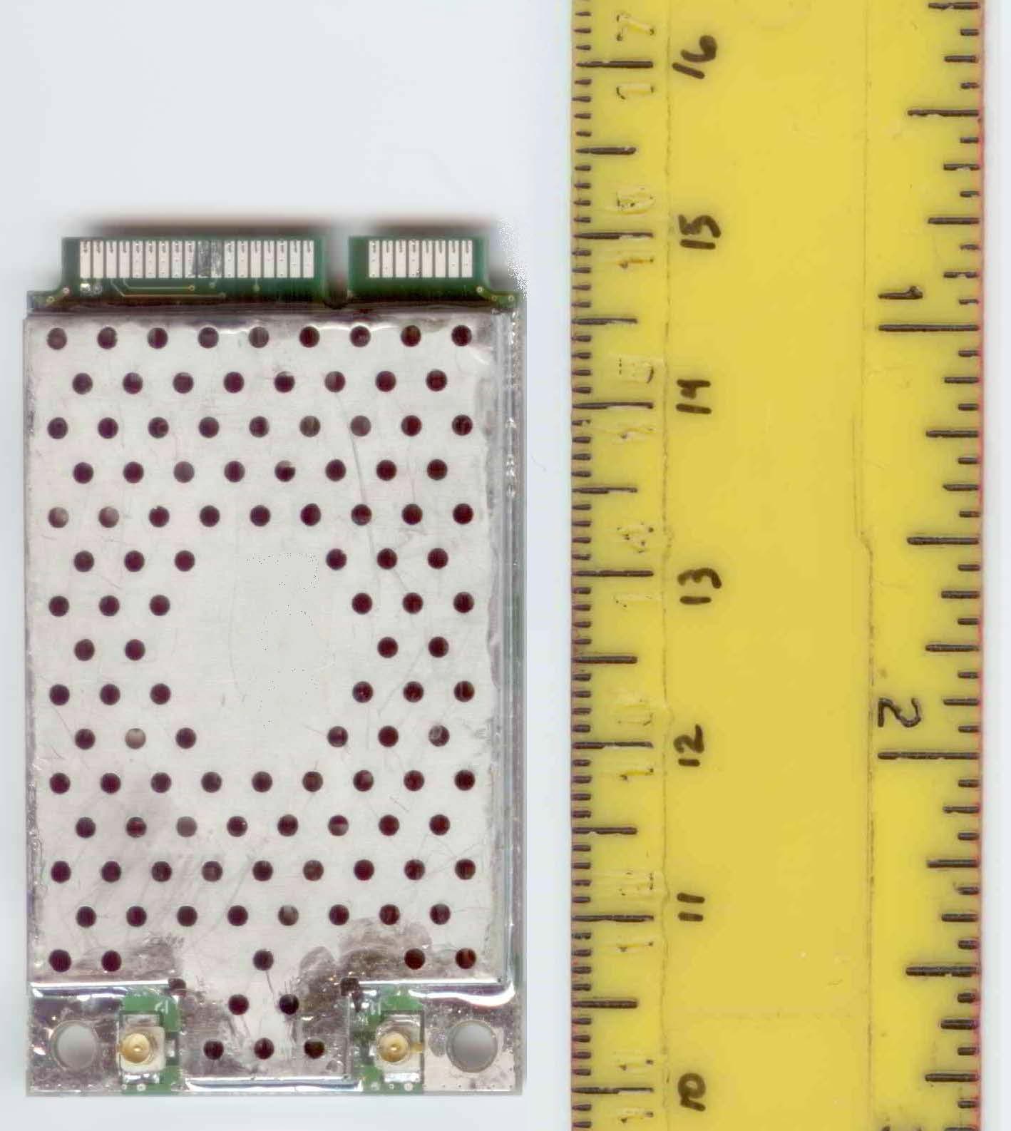
Click to zoom
Application Details
- Equipment Class
- DSS - Part 15 Spread Spectrum Transmitter
- Date of Grant
- Oct 09, 2012
- Application Purpose
- Original Equipment
- Date of Application
- Oct 09, 2012
- Equipment Note
- IM11
- Frequency Range
- 902.75000000 - 927.25000000
- Country
- United States
Documents & Files
Document Text
Text extracted from the exhibit documents filed with the FCC. Open a document above to read the original.
Users Manual
IM11 RFID Radio, 900 MHz Compliance Insert Model IM11 Graphic 2006 (FCC), 2001(C tick AS/NZS) For Users in English-Speaking Regions This marking indicates that the user should read all included documentation before use. Retain this supplement for future reference. Users of this product are cautioned to use accessories and peripherals approved by Intermec Technologies Corporation. The use of accessories other than those recommended, or changes to the product that is not approved by Intermec Technologies Corporation, may void the compliance of this product and may result in the loss of the user’s authority to operate the equipment. Radiation Exposure Statement Warning: This equipment complies with International Commission on Non- Ionizing Radiation Protection (ICNIRP), IEEE C95.1, Federal Communications Commission Office of Engineering and Technology (OET) Bulletin 65, Canada RSS-102, and European Committee for Electrotechnical Standardization (CENELEC) limits for exposure to radio frequency (RF) radiation. Use of antennas and accessories not authorized may void the compliance of this product and may result in RF exposures beyond the limits established for this equipment. When installing and using this product, a 25.4 cm (10 in.) passing distance must be maintained from the body or head of the user or nearby persons and the antenna. The antenna must not be touched during transmitter operation. For Users in U.S.A. and Canada Caution: FCC Compliance Intermec RFID systems require professional installation. Antennas: The users of this product are cautioned to use antennas and accessories approved by Intermec Technologies Corporation. The use of antennas and accessories that are not approved by Intermec Technologies Corporation may void the compliance of this product and may result in the loss of the user’s authority to operate the equipment. U.S.A. Digital Emissions Compliance This device complies with part 15 of the FCC Rules. Operation is subject to the following two conditions: (1) this device may not cause harmful interference, and (2) this device must accept any interference received, including interference that may cause undesired operation. This equipment has been tested and found to comply with the limits for a Class B digital device, pursuant to Part 15 of the FCC Rules. These limits are designed to provide reasonable protection against harmful interference in a residential installation. This equipment generates, uses, and can radiate radio frequency energy and, if not installed and used in accordance with the instructions, may cause harmful interference to radio communications. However, there is no guarantee that interference will not occur in a particular installation. If this equipment does cause harmful interference to radio or television reception, which can be determined by turning the equipment off and on, the user is encouraged to try to correct the interference by one or more of the following measures: • Reorient or relocate the radio or television receiving antenna. • Increase the separation between the computer equipment and receiver. • Connect the equipment into an outlet on a circuit different from that to which the radio or television receiver is connected. • Consult the dealer or an experienced radio television technician for help. Canadian Compliance This device complies with Industry Canada license-exempt RSS standards. Operation is subject to the following two conditions: (1) this device may not cause harmful interference, and (2) this device must accept any interference received, including interference that may cause undesired operation. CAN ICES-3 (B)/NMB-3 (B) External Antenna Statement Under Industry Canada regulations, this radio transmitter may only operate using an antenna of a type and maximum (or lesser) gain approved for the transmitter by Industry Canada. To reduce potential radio interference to other users, the antenna type and its gain should be so chosen that the equivalent isotropically radiated power (e.i.r.p.) is not more than that necessary for successful communication. This radio transmitter IC: 1223A-IM11 has been approved by Industry Canada to operate with the antenna types listed below with the maximum permissible gain and required antenna impedance for each antenna type indicated. Antenna types not included in this list, having a gain greater than the maximum gain indicated for that type, are strictly prohibited for use with this device. Description Gain (dBi) Cable Loss (dB) Impedance (Ohms) Panel CP 8.0 2.4 50 Panel LP 8.0 2.4 50 Patch CP 7.0 2.4 50 Patch LP 6.0 2.4 50 Dipole Multi-Axis 5.5 2.4 50 Dipole Dual-Pole 5.0 0 50 Yagi 5.5 0 50 Gain figures are linear dBi (decibels over isotropic). Antenna polarization is described as LP (linear polarized), or CP (circular polarized). For Users in Canada (fr) (below here translate to French) This marking indicates that the user should read all included documentation before use. Retain this supplement for future reference. Users of this product are cautioned to use accessories and peripherals approved by Intermec Technologies Corporation. The use of accessories other than those recommended, or changes to the product that is not approved by Intermec Technologies Corporation, may void the compliance of this product and may result in the loss of the user’s authority to operate the equipment. Radiation Exposure Statement Warning: This equipment complies with International Commission on Non- Ionizing Radiation Protection (ICNIRP), IEEE C95.1, Federal Communications Commission Office of Engineering and Technology (OET) Bulletin 65, Canada RSS-102, and European Committee for Electrotechnical Standardization (CENELEC) limits for exposure to radio frequency (RF) radiation. Use of antennas and accessories not authorized may void the compliance of this product and may result in RF exposures beyond the limits established for this equipment. When installing and using this product, a 25.4 cm (10 in.) passing dista…
Text truncated - open the document above for the full version.
Users Manual
IM4 Module Integration Guide iiIM4 Module Integration Guide Intermec Technologies Corporation Worldwide Headquarters 6001 36th Ave.W. Everett, WA 98203 U.S.A. www.intermec.com The information contained herein is proprietary and is provided solely for the purpose of allowing customers to operate and service Intermec-manufactured equipment and is not to be released, reproduced, or used for any other purpose without written permission of Intermec. Information and specifications contained in this document are subject to change without prior notice and do not represent a commitment on the part of Intermec Technologies Corporation. ©2005-2007 Intermec Technologies Corporation. All rights reserved. The word Intermec, the Intermec logo, Norand, ArciTech, Beverage Routebook, CrossBar, dcBrowser, Duratherm, EasyADC, EasyCoder, EasySet, Fingerprint, INCA (under license), i-gistics, JANUS, LabelShop, MobileLAN, Picolink, Ready-to-Work, RoutePower, Sabre, ScanPlus, ShopScan, Smart Mobile Computing, SmartSystems, TE 2000, Trakker Antares, and Vista Powered are either trademarks or registered trademarks of Intermec Technologies Corporation. There are U.S. and foreign patents pending. IM4 Module Integration Guideiii Document Change Record This page records changes to this document. The document was originally released as version 001. Version Number DateDescription of Change 00210/2006Adjusted frequency range information. 00305/2007Corrections made to voltage ratings and current requirements. IM4 Module Integration Guideiv IM4 Module Integration Guidev Contents Before You Begin . . . . . . . . . . . . . . . . . . . . . . . . . . . . . . . . . . . . . . . . . . . . . . . . . . . . . . . . .vi Safety Icons. . . . . . . . . . . . . . . . . . . . . . . . . . . . . . . . . . . . . . . . . . . . . . . . . . . . . . . vi Global Services and Support . . . . . . . . . . . . . . . . . . . . . . . . . . . . . . . . . . . . . . . . . . vi Who Should Read This Document? . . . . . . . . . . . . . . . . . . . . . . . . . . . . . . . . . . . vii About the IM4. . . . . . . . . . . . . . . . . . . . . . . . . . . . . . . . . . . . . . . . . . . . . . . . . . . . . . . . . . . 9 Configuring the IM4 as a PC Card Module (Default) . . . . . . . . . . . . . . . . . . . . . . . . . . . . 10 Configuring the IM4 as a Serial Module . . . . . . . . . . . . . . . . . . . . . . . . . . . . . . . . . . . . . . 11 Understanding the IM4 Operating Modes . . . . . . . . . . . . . . . . . . . . . . . . . . . . . . . . . . . . . 13 Heat Dissipation Requirements . . . . . . . . . . . . . . . . . . . . . . . . . . . . . . . . . . . . . . . . . . . . . 14 Power Requirements . . . . . . . . . . . . . . . . . . . . . . . . . . . . . . . . . . . . . . . . . . . . . . . . . . . . . 14 Antenna Requirements . . . . . . . . . . . . . . . . . . . . . . . . . . . . . . . . . . . . . . . . . . . . . . . . . . . 15 Specifications . . . . . . . . . . . . . . . . . . . . . . . . . . . . . . . . . . . . . . . . . . . . . . . . . . . . . . . . . . . 17 Before You Begin viIM4 Module Integration Guide Before You Begin This section provides you with safety information, technical support information, and sources for additional product information. Safety Icons This section explains how to identify and understand cautions and notes within this document. Global Services and Support Warranty Information To understand the warranty for your Intermec product, refer to your OEM agreement. Disclaimer of warranties: The sample code included in this document is presented for reference only. The code does not necessarily represent complete, tested programs. The code is provided “as is with all faults.” All warranties are expressly disclaimed, including the implied warranties of merchantability and fitness for a particular purpose. Web Support Visit the Intermec web site at www.intermec.com to download our current documents (in PDF). To order printed versions of the Intermec manuals, contact your local Intermec representative or distributor. Visit the Intermec technical knowledge base (Knowledge Central) at intermec.custhelp.com to review technical information or to request technical support for your Intermec product. A caution alerts you to an operating procedure, practice, condition, or statement that must be strictly observed to prevent equipment damage or destruction, or corruption or loss of data. Note: Notes either provide extra information about a topic or contain special instructions for handling a particular condition or set of circumstances Before You Begin viiIM4 Module Integration Guide Telephone Support These services are available from Intermec Technologies Corporation. Outside the U.S.A. and Canada, contact your local Intermec representative. To search for your local representative, from the Intermec web site, click Contact. Who Should Read This Document? This IM4 Module Integration Guide (P/N 944-632-xxx) explains how to integrate the IM4 module into a computer or other device. It is written for the person who will be evaluating the IM4 to integrate into their device or for the person who will be engineering the device to accommodate the IM4. Before you install and configure the IM4, you should be familiar with Intermec RFID systems and how to implement them. You should also be familiar with your network and general networking terms, such as IP address. ServicesDescription In the USA and Canada call 1-800-755-5505 and choose this option Order Intermec products • Place an order. • Ask about an existing order. 1 and then choose 2 Order Intermec mediaOrder printer labels and ribbons.1 and then choose 1 Order spare partsOrder spare parts.1 or 2 and then choose 4 Technical SupportTalk to technical support about your Intermec product. 2 and then choose 2 Service• Get a return authorization number for authorized service center repair. • Request an on-site repair technician. 2 and then choose 1 Service contracts• Ask about an existing contract. •Renew a contract. • …
Text truncated - open the document above for the full version.
Cover Letter(s)
WTD 12.7.3 FCC Compliance Opinion ITRM0323 Information about the Applicant Grantee (Company Name) Intermec Technologies Corporation FCC Contact Person Dave Fry Address 550 Second St. SE City, State, Zip Cedar Rapids, IA 52401-2023 Job Number ITRM0323 Model IM11 FCC ID EHA-IM11 Agent Approval Type Original Equipment Class DSS Part 15 Spread Spectrum Transmitter Rule Part 15.247 Overview The IM11, FCC ID EHA-IM11, is an RFID module operating within the 902.75 - 927.25 MHz band as a frequency hopping spread spectrum transmitter. It is designed to read and write information to passive RFID tags. Limited modular approval is sought to require professional installation. The device meets all of the requirements for modular approval, but will be installed in Intermec RFID products only. Confidentiality requested for allowed files. Request is properly addressed and referenced. A letter listing the applicable modular requirements was submitted. Recommendation All items have been resolved and completed to my satisfaction; therefore I recommend this application for approval. Signature Dave Tolman, TCB Committee 10/8/2012
Cover Letter(s)
Date: September 14, 2102 Telecommunication Certification Body (and/or) Federal Communications Commission Authorization and Evaluation Division 7435 Oakland Mills Road Columbia, Maryland 21046 Subject: Application for Grant of Original Certification Dear Application Examiner, Intermec Technologies Corporation is submitting this application for Original Certification for the IM11 RFID radio, FCC ID: EHA-IM11. The IM11 RFID radio operates at 1.0 Watt as frequency hopping spread spectrum transmitter operating within the 902.75 – 927.25 MHz band under Section 15.247. The radio is designed to read and write information to passive RFID tags. This application requests the IM11 be granted “Limited Modular Approval” to accommodate “Professional Installation”. RFID technology is used in specific locations and is limited in marketing to industrial and commercial users. Intermec RFID products are never sold to the general public. The installations are always overseen by Intermec systems engineers or RFID certified partners. The integrators guide informs OEM users of their regulatory obligations. A letter confirming the modular approval requirements is contained within this application. This radio is to be used within several Intermec products, integration testing will include verification the transmitter characteristics remain as documented in this application and the end product complies with all FCC regulations. Integration testing will be reported under Certification, Declaration of Conformity or Verification rules defined by 47 CFR Parts 2 and 15. Your efforts in reviewing this application are greatly appreciated. Please contact me if there are questions or additional information needed concerning this request. Sincerely, Dave Fry Sr. EMC Engineer, iNARTE ATL-0095-E Intermec Technologies Corporation Dave Fry MS GR05 550 Second Street SE Cedar Rapids, IA 52401 Desk tel 319.369.3353 Lab tel 319.846.2415 Fax tel 319.846.2475 [email protected] 6001 36 th Avenue West Everett, Washington 98203 United States tel 425.348.2600 fax 425.355.9551 www.intermec.com
Cover Letter(s)
Page 1 of 3 Date: September 14, 2012 Telecommunication Certification Body (and/or) Federal Communications Commission Authorization and Evaluation Division 7435 Oakland Mills Road Columbia, Maryland 21046 ATTESTATION FOR MODULAR APPROVAL Ref FCC ID: EHA-IM11 Gentlemen; In order to obtain a modular transmitter approval, a cover letter requesting modular approval must be submitted and the 8 numbered requirements identified below must be addressed in the application for equipment authorization. This application requests the IM11 be granted “Limited Modular Approval” to accommodate “Professional Installation”. RFID technology is used in specific locations and is limited in marketing to industrial and commercial users. Intermec RFID products are never sold to the general public. The installations are always overseen by Intermec systems engineers or RFID certified partners. OEM integrators guide inform users of their regulatory obligations. 1. The modular transmitter must have its own RF shielding. This is intended to ensure that the module does not have to rely upon the shielding provided by the device into which it is installed in order for all modular transmitter emissions to comply with Part 15 limits. It is also intended to prevent coupling between the RF circuitry of the module and any wires or circuits in the device into which the module is installed. Such coupling may result in non-compliant operation. Intermec Technologies is provided the radio as a shielded assembly. The radio is shown in this report reveals the transmitter emissions comply with the limits defined by the regulatory agencies. 2. The modular transmitter must have buffered modulation/data inputs (if such inputs are provided) to ensure that the module will comply with Part 15 requirements under conditions of excessive data rates or over-modulation. The communication to the radio uses digital technology. The communication buffering eliminates the ability to over-modulate the radio under all conditions. 3. The modular transmitter must have its own power supply regulation. This is intended to 6001 36 th Avenue West Everett, Washington 98203 United States tel 425.348.2600 fax 425.355.9551 www.intermec.com Page 2 of 3 ensure that the module will comply with Part 15 requirements regardless of the design of the power supplying circuitry in the device into which the module is installed. The IM11 radio board uses an onboard voltage regulation. 4. The modular transmitter must comply with the antenna requirements of Section 15.203 and 15.204(c). The antenna must either be permanently attached or employ a “unique” antenna coupler (at all connections between the module and the antenna, including the cable). Any antenna used with the module must be approved with the module, either at the time of initial authorization or through a Class II permissive change. The “professional installation” provision of Section 15.203 may not be applied to modules. The IM11 radio module utilizes unique connectors, RF cables for the system must be supplied by Intermec so antenna / cable system gain remains below the +6 dBi linear gain limit. Some RFID antennas are sourced with standard connectors; the approved antenna list is published in the user documentation provided with products that utilize this radio module. The professional installation provisions under Section 15.203 are addressed in the second paragraph of this letter. Limited Modular Approval is requested. 5. The modular transmitter must be tested in a stand-alone configuration, i.e., the module must not be inside another device during testing. This is intended to demonstrate that the module is capable of complying with Part 15 emission limits regardless of the device into which it is eventually installed. Unless the transmitter module will be battery powered, it must comply with the AC line conducted requirements found in Section 15.207. AC or DC power lines and data input/output lines connected to the module must not contain ferrites, unless they will be marketed with the module (see Section 15.27(a)). The length of these lines shall be length typical of actual use or, if that length is unknown, at least 10 centimeters to insure that there is no coupling between the case of the module and supporting equipment. Any accessories, peripherals, or support equipment connected to the module during testing shall be unmodified or commercially available (see Section 15.31(i)). Testing herein shows the radio tested as a module. The setup photographs show no ferrites or decoupling devices to reduce emissions of the module. AC power line conducted emissions are within the test report. 6. The modular transmitter must be labeled with its own FCC ID number, and, if the FCC ID is not visible when the module is installed inside another device, then the outside of the device into which the module is installed must also display a label referring to the enclosed module. This exterior label can use wording such as the following: “Contains Transmitter Module FCC ID: XYZMODEL1” or “Contains FCC ID: XYZMODEL1.” Any similar wording that expresses the same meaning may be used. The Grantee may either provide such a label, an example of which must be included in the application for equipment authorization, or, must provide adequate instructions along with the module which explain this requirement. In the latter case, a copy of these instructions must be included in the application for equipment authorization. Page 3 of 3 Enclosed within this report are label diagrams with similar verbiage shown above. The module will show the FCC ID. If when integrated the radio module identifier is not visible, the exterior will show the “Contains TX FCC ID:” text. 7. The modular transmitter must comply with any specific rule or operating requirements applicable to the transmitter and the manufacturer must provide adequate instructions along with the module to explain any such requirements. A copy of these instructions must be included …
Text truncated - open the document above for the full version.
Cover Letter(s)
Date: September 14, 2012 Telecommunication Certification Body (and/or) Federal Communications Commission Authorization and Evaluation Division 7435 Oakland Mills Road Columbia, Maryland 21046 Subject: Long Term Confidentiality FCC ID: EHA-IM11 To whom it may concern, We hereby respectfully request that under the provisions of 47 CFR 0.457 and 0.459, the documents listed below and attached with this application for certification be provided with permanent confidential status. Schematics Theory of Operation Frequency Block Diagrams Any exhibit / information for which we have requested confidentiality, but which may not be accorded such treatment by the FCC, should be returned to us. The documents above contain trade secrets and proprietary information that are treated as confidential and not released to the public. Substantial competitive harm to Intermec or our suppliers could result should they be made available to the public. Please contact me if there are questions or additional information needed concerning this request. Sincerely, Dave Fry Sr. EMC Engineer, iNARTE ATL-0095-E Intermec Technologies Corporation Dave Fry MS GR05 550 Second Street Cedar Rapids, IA 52401 Desk tel 319.369.3353 Lab tel 319.846.2415 Fax tel 319.846.2475 [email protected] 6001 36 th Avenue West Everett, Washington 98203 United States tel 425.348.2600 fax 425.355.9551 www.intermec.com
ID Label/Location Info
IM11 FCC, Canada label and placement Label is located on the back of the module, side without antenna connectors, to accommodate heat sinking for high duty cycle operation. (mm)
Operational Description
Dave Fry Technologies Corporation Sr. EMC Engineer EMC Test Laboratory Sept. 12, 2012 Cedar Rapids, IA USA A B C D E F G H T E S T E D Intermec P/N Intermec MN, Supplier PN Description Ga in Cable Loss Antenna/cable system gain (T) (dBi)* (dB) (dBi) F - G = H 1 T - - , Huber Suhner 1309.17.0085-X Panel, Linear 8.0 2 .4 5.6 2 T - - , Huber Suhner 1309-56-0001-X Panel RCP 8.0 2.4 5.6 3 T 805-606-002 Radiall, ROS-915 Patch RCP -0.5 0 -0.5 4 T - - , Intermec Yagi, Linear 5.2 0 5.2 5 T - - , Intermec Dual pole 4 x 4 in, Linear 5.0 0 5.0 6 - - , Intermec Dual pole 3 x 3 in, Linear 2.5 0 2.5 7 805-609-001 IA33A, Cushcraft SP9028PC156RSM Patch CP 4.0 0 4.0 8 805-622-002 IA39A, Kathrein 25-178 Patch CP 6.5 2.4 4.1 9 805-623-002 IA39D, Kathrein 25-278 Patch CP 5.0 2.4 2.6 10 805-626-001 IA36B, Kathrein 25-578 Patch LCP 6.0 2.4 3.6 11 805-629-001 IA33C, Mobile Mark PN10-915RCPI Patch C P 7.0 2.4 4.6 12 805-654-001 IA33G, Huber Suhner 84024995 Panel RCP 5.5 2.4 3.1 13 805-654-002 IA34A, Huber Suhner 84024996 Panel LCP 5.5 2.4 3.1 14 805-655-001 IA33H, Huber Suhner 84024999 Panel RCP 7.0 2.4 4.6 15 805-655-002 IA34B, Huber Suhner 84025000 Panel LCP 7.0 2.4 4.6 16 805-816-002 IA33E, Cushcraft S9026XR1RRN Patch CP 3.0 2.4 0.6 17 - - , Huber Suhner 1309-57-0087-X Panel RCP 7.0 2.4 4.6 18 - - , Mobile Mark PN7-915I-FL Panel RCP 4.0 2.4 1.6 19 - - , Mobile Mark EDN 191-1550 Panel RCP 4.0 2.4 1.6 20 - - , Kathrein 520 10087 Panel RCP 7.5 2.4 5.1 21 - - , Kathrein 520 10073 Panel RCP 5.2 2.4 2.8 22 T - - , Kathrein 520 10092 Patch CP -30.0 2.4 -32.4 23 T - - , Intermec PIFA, Omni -1.0 0 -1.0 24 - - , Huber Suhner 1309.17.0089-X Panel RCP 4.5 2.4 2.1 25 T - - , NeWave Wave-N7 7ft. Multi-Axis Dipole 5.5 2.4 3 .1 26 - - , NeWave Wave-N5 5ft. Multi-Axis Dipole 4.5 2.4 2. 1 27 - - , NeWave Wave-N3 3ft. Multi-Axis Dipole 3.0 2.4 0. 6 28 - - , Mobile Mark BP6-915RCPI Panel RCP 2.5 2.4 0.1 29 - - , Laird S9025P Panel RCP 2.5 2.4 0.1 -X = blank or A, B, C.... pricing code* CP gain dBiC = dBi + 3 CP circular polarized RCP right hand circular polarized antenna LCP left hand circular polarized antenna Antenna List - IM11 RFID Reader - MN: IM11 AntennasIM11 RFID ReaderModel IM11 TESTED TESTED TESTED TESTED TESTED Intermec Part Number N/A see Product Links N/A see Product Links 805-606-0 02 N/A N/A Proposed Intermec M/N N/A N/A N/A N/A N/A Description 915, 8 dBi, linear, N 915, 11 dBic, RHCP, N (RP) 915, 2.5 dBic, RHCP patch Yagi, 915 MHz linear dual pole linear Frequency Range 902-928 MHz 902-928 MHz 902 - 928 MHz 902 - 928 MHz 902 - 928 MHz Ant.-cable System Gain 5.6 dBi 4.6 dBi -0.5 dBi 5.2 dBi 5 dBi Gain 8 dBi linear 8 dBi linear -0.5 dBi 5.2 dBi linear 5 dBi linear Impedance 50 Ohms 50 Ohms 50 Ohms 50 Ohms 50 Ohms VSWR max. 1.7:1 max. 1.5 < 1.0:1 1.5:1 1.5:1 Axial Ratio 3 dB 0 dB 3 dB 1 dB Polarization Linear Circular, RH Circular, RH linear linear Front-to-Back Ratio Max -11dB Max -20 dB 10 dB Maximum Input Power 6 Watts 6 Watts 20 Watts 1 Watt 1 Watt H-Plane Beamwidth 63 degrees (At 3dB) 120 degrees 45 degrees at 3 dB 45 degrees at 3 dB E-Plane Beamwidth 70 degrees (At 3dB) 30 degrees (At 3dB) 120 degrees 50 degrees at 3 dB 50 degrees at 3 dB Connector N Reverse Polarity TNC Reverse Polarity MMCX MMCX MMCX Cable Length N/A N/A 2.5 inch Weight 0.7 kg (1.54lbs.) 2.8 kg (6.17 lbs.) 0.5 kg (1.1 lbs) Dimensions 190 x 190 x 30 mm (7.5” x 7.5” x 1.2”) 630 x 320 x 40 mm (24.8” x 12.98” x 1.57”) 3.1 x 3.1 x 0.25 inches(79 x 79 x 7 mm) 4.25 x 4 inches(118 x 112 mm) 4 x 4 inches(112 x 112 mm) ShockRoHS, WEEE Status Complies Complies Mounting Hardware 84007206 Mnting Bracket (separate) N/A N/A N/A Manufacturer Huber Suhner Huber Suhner Radiall Intermec Intermec Manufacturer M/N 1309.17.0085 1309-56-001-x ROS-915 Manufacturer P/N Item No. 84029200 Item No. 84039146 Product ID SPA-915/70/8/0/V SPA-915/63/11/0/RCP AntennasIM11 RFID ReaderModel IM11 Intermec Part NumberProposed Intermec M/NDescriptionFrequency RangeAnt.-cable System GainGainImpedanceVSWRAxial RatioPolarizationFront-to-Back RatioMaximum Input PowerH-Plane BeamwidthE-Plane BeamwidthConnectorCable LengthWeightDimensionsShockRoHS, WEEE StatusMounting HardwareManufacturerManufacturer M/NManufacturer P/NProduct ID N/A 805-609-001 805-622-002 805-623-002 805-626-001 N/A IA33A IA39A IA39D IA36B dual pole linear IA33A: 915, 7dBi, RHC Pol, SMA (RP) IA39A: 915, 9.5 dBic, Cir Pol, N (RP) IA39D: 915, 8 dBic, Cir Pol, N (RP) IA36B: 915, 6dBi, Vert Pol, N (RP) 902 - 928 MHz 902 - 928 MHz 902 - 928 MHz 865-928 MHz 8 65-928 MHz 2.5 dBi 4 dBi 4.1 dBi 2.6 dBi 3.6 dBi 2.5 dBi linear 4 dBi linear 6.5 dBi linear 5 dBi linea r 6 dBi linear 50 Ohms 50 Ohms 50 Ohms 50 Ohms 50 Ohms 1.5:1 1.5:1 <1.3:1 <1.3:1 <1.5:1 1 dB 2 dB < 3 dB over entire half power beam 3 dB N/A linear Circular, RH Circular, LH Circular, LH Patch 18 dB > 15 dB > 20 dB >20 dB 1 Watt 1 Watt 100 Watts (at 50oC) 100 Watts (at 50oC) 1 00 Watts (at 50oC) 45 degrees at 3 dB 65 degrees at 3 dB 80 degrees (hal f power) 60 degrees (half power) 90 degrees (half pow er) 50 degrees at 3 dB 65 degrees at 3 dB 30 degrees (hal f power) 55 degrees (half power) 70 degrees (half pow er) MMCX SMA Reverse Polarity N Reverse Polarity N Reverse Polarity N Reverse Polarity 156 Inches N/A N/A N/A 1.25 lbs 5.2 lbs (2.4 kg) 3.8 lb (1.7 kg) 3.3 lb (1.5 kg) 3 x 3 inches(76 x 76 mm) 19.3 x 6.1 x 1.9 inches(490 x 155 x 49 mm) 12.2 x 10.3 x 2.4 inches(310 x 262 x 59 mm) 10.3 x 6.1 x 1.9 inches(262 x 155 x 49 mm) N/A N/A 203-734-001 kit included203-733-001 kit order seperately203-735-001 order seperately203-737-001 order seperately 203-734-001 kit included203-733-001 kit order seperately203-735-001 order seperately203-737-001 order seperately 203-734-001 kit included203-733-001 kit order seperately203-735-001 order seperately203-737-001 order seperately Intermec Cushcraft-Laird Kathrein Kathrein Kathrein 25-178 25-278 25-578 SP9028PC156RSM AntennasIM11 RFID ReaderModel IM11 Intermec Part NumberProposed Intermec M/NDescriptionFrequency RangeAnt.-cabl…
Text truncated - open the document above for the full version.
RF Exposure Info
RF Exposure - MPE Estimates, RFID frequency of operation 902.75 - 927.25 MHz IM11 RFID Radio Module FCC regulations compliance 47 CFR 15.247(i) Systems operating under the provisions of this section shall be operated in a manner that ensures that the public is not exposed to radio frequency energy levels in excess of the Commission's 47 CFR 2.1091 (b). The system is classified as a mobile transmitter. 47 CFR 2.1091(c) The EUT is categorically excluded from routine environmental evaluation. 47 CFR 1.1310 General Public Limit mW/cm 47 CFR 1.1310 General Public Limit mW/cm47 CFR 1.1310 General Public Limit mW/cm 47 CFR 1.1310 General Public Limit mW/cm² = F(MHz) / 1500 = F(MHz) / 1500 = F(MHz) / 1500 = F(MHz) / 1500 Limit0.601mW/cm² 902MHz System Description The IM11 RFID radio module is utilized within Intermec RFID fixed readers. Antennas in this estimate represent the highest gain antennas used with the IM11. The user manual instruct to provide for a separation distance of 25.4-cm or greater distance between the IM11 RFID system antennas and the head or torso of the user or near by persons. Radio Disc / Rule Radio Disc / RuleRadio Disc / Rule Radio Disc / RuleMHz - MHz - MHz - MHz - MHz MHz MHz MHz Milli…
Text truncated - open the document above for the full version.
Contact Information
Applicant
Brian Rudick(VP & GC, Honeywell Scanning & Mobility)
Test Firm
Northwest EMC, Inc.Greg Kiemel
Technical Specifications
| # | Rule Parts | Frequency Range | Power Output |
|---|---|---|---|
| 1 | 15C | 902.75 MHz - 927.25 MHz | 938.00 mW |
Other Applications from Intermec Technologies Corporation
EHA-1015CP01X1
Sep 29, 20131015CP01
Equipment Class
NII - Unlicensed National Information Infrastructure TX
EHA-1015CP01SX1
Sep 08, 20131015CP01S
Equipment Class
PCE - PCS Licensed Transmitter held to ear
EHA-RC12ABGN
Aug 19, 2013WLAN board
Equipment Class
DSS - Part 15 Spread Spectrum Transmitter
EHA-1000CP01F
Feb 19, 20131000CP01F9, 1000CP02F9, 1001CP01F9
Equipment Class
DTS - Digital Transmission System
EHA-INBT02
Dec 11, 2012BT Board
Equipment Class
DSS - Part 15 Spread Spectrum Transmitter