EHA-IM5R3IM5r3
Intermec Technologies Corporation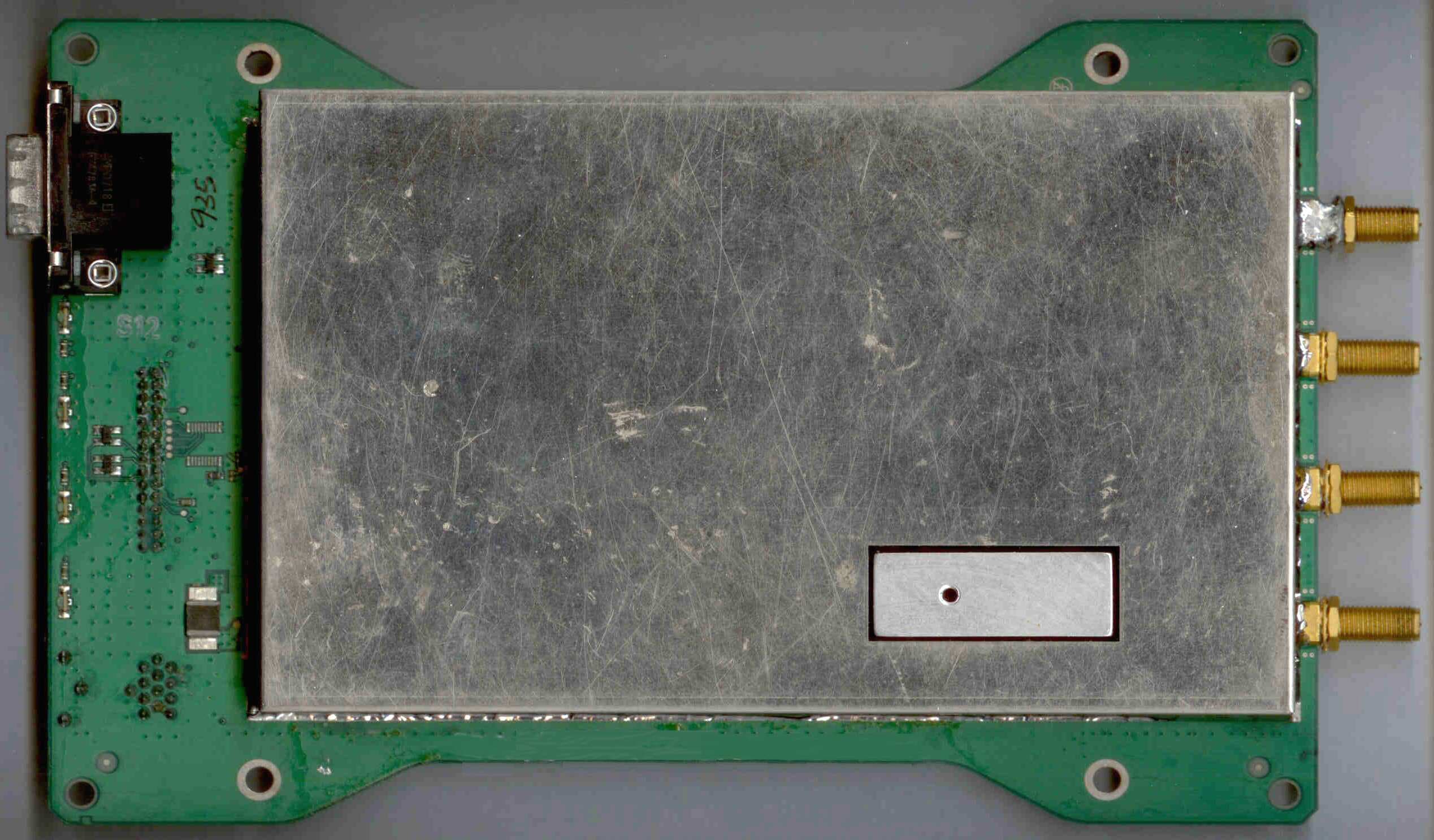
Click to zoom
Application Details
- Equipment Class
- DTS - Digital Transmission System
- Date of Grant
- Mar 29, 2009
- Application Purpose
- Original Equipment
- Date of Application
- Mar 29, 2009
- Equipment Note
- IM5r3
- Frequency Range
- 902.75000000 - 927.25000000
- Country
- United States
Documents & Files
Document Text
Text extracted from the exhibit documents filed with the FCC. Open a document above to read the original.
Users Manual
Model IM5 Compliance Insert (Languages needed: English, French-Canadian, Mexican-Spanish, Brazilian-Portuguese, German, Russia, Simplified Chinese, Traditional Chinese, and Korean) Caution: This marking indicates that the user should read all included documentation before use. Retain this supplement for future reference. Users of this product are cautioned to use accessories and peripherals approved by Intermec Technologies Corporation. The use of accessories other than those recommended, or changes to the product that is not approved by Intermec Technologies Corporation, may void the compliance of this product and may result in the loss of the user’s authority to operate the equipment. Battery, Charger or Power Supply Information Caution: For Power Supply use Intermec Model AE34. No user-serviceable parts. For Users within North and South America (Translations needed: English, French-Canadian, Mexican-Spanish, and Brazilian- Portuguese – unless otherwise noted. These translations are below from a similar CI) English, French Canadian For Users within North and South America This device complies with Part 15 of the FCC rules and with RSS-210 of Industry Canada. Operation is subject to the following two conditions: (1) This device may not cause harmful interference, and (2) This device must accept any interference received, including interference that can cause undesired operation. FCC Digital Emissions Compliance (No translation needed – English only) This equipment has been tested and found to comply with the limits for a Class B digital device, pursuant to Part 15 of the FCC Rules. These limits are designed to provide reasonable protection against harmful interference in a residential installation. This equipment generates, uses, and can radiate radio frequency energy and, if not installed and used in accordance with the instructions, may cause harmful interference to radio communications. However, there is no guarantee that interference will not occur in a particular installation. If this equipment does cause harmful interference to radio or television reception, which can be determined by turning the equipment off and on, the user is encouraged to try to correct the interference by one or more of the following measures: • Reorient or relocate the radio or television receiving antenna. • Increase the separation between the computer equipment and receiver. • Connect the equipment into an outlet on a circuit different from that to which the radio or television receiver is connected. • Consult the dealer or an experienced radio television technician for help. Canadian Digital Apparatus Compliance (Translations needed: English and French-Canadian) This Class B digital apparatus meets all requirements of the Canadian Interference-Causing Equipment Regulations. Radiation Exposure Statement This equipment complies with FCC and Canada RSS-102 radiation exposure limits set forth for an uncontrolled environment. End users must follow the specific operating instructions for satisfying RF exposure compliance. Please follow operation instructions as documented for this product. This product meets the RF exposure guidelines when used with the Intermec accessories supplied or designated for this product. Use of other accessories may not ensure compliance with RF exposure guidelines. When installing and using the Intermec IM5 RFID radio, a 23-cm (9-inch) passing distance must be maintained from the body or head of the user or nearby persons and the IM5 antenna. The antenna must not be touched during transmitter operation. À l’attention des utilisateurs en Amérique du Nord et du Sud Ce dispositif est conforme à la partie 15 des règlements du FCC et à la norme RSS-210 d’Industrie Canada. L’utilisation est assujettie aux deux conditions suivantes : (1) Ce dispositif ne doit pas causer d’interférence dommageable et (2) Ce dispositif doit tolérer toute interférence, incluant l’interférence pouvant causer un fonctionnement indésirable. Conformité aux normes canadiennes sur les appareils numériques Cet appareil numérique de la classe B respecte toutes les exigences du Réglement sur le matériel brouilleur du Canada. Énoncé sur l'exposition aux radiations Cet appareil est conforme aux limites d’exposition aux radiations du FCC des États-Unis et la norme RSS-102 canadienne pour un environnement non contrôlé. Les utilisateurs finaux doivent suivre les modes d’emploi spécifiques afin de respecter les directives sur l’exposition aux RF. Veuillez suivre le mode d’emploi dans la documentation accompagnant ce produit. Ce produit est conforme aux directives sur l’exposition aux RF lorsqu'il est utilisé avec les accessoires Intermec fournis ou conçus pour ce produit. L’utilisation d’autres accessoires peut ne pas garantir la conformité aux directives sur l’exposition aux RF. Lorsque vous installez et utilisez le lecteur d’IDRF IM5 Intermec, une distance de passage de 23 cm doit être respectée depuis le corps ou la tête de l’utilisateur ou des personnes à proximité et l’antenne IM5. On ne doit pas toucher à l’antenne pendant le fonctionnement de l’émetteur Approved Antenna List for IM5 This device has been designed to operate with the antennas listed in the next table. Each of these antennas has a maximum effective gain (antenna gain minus cable loss) of 6 dB. Antennas not included in this list or having an effective gain (antenna gain minus cable loss) of greater than 6 dB are strictly prohibited for use with this device. The required antenna impedance is 50 ohms. To reduce potential radio interference to other users, the antenna type and its gain should be so chosen that the equivalent isotropically radiated power (e.i.r.p.) is not more than that permitted for successful communication. Gain figures are linear dBi (decibels over isotropic). Antenna polarization is described as LP (linear polarized), CP (circular polarized), LCP (left circular polarized), or RCP (right circular polarized). Liste d'antennes approuvées po…
Text truncated - open the document above for the full version.
Users Manual
Installation and IM5 Reader Module Quick Start Guide 2IM5 Reader Module Installation and Quick Start Guide Packing List Checktoensurethatyoureceivetheseitems: SIntermec R IM5 Reader Module SCompliance Statement SWarranty Card Host Communication Host communication comes through the 9-pin female D-sub connector. RS-232 standards are supported as ordered from the factory or service center. SThe maximum data rate is 115.2K baud, with 8 data bits, no parity bit, and 1 stop bit. SThe maximum RS-232 distance from the reader to the host, modem, or other physical controller interface is 50 feet (15.2 meters). RS-232 Connections Pin NumberDefinition 2TXD (Transmit Data) to the host 3RXD (Receive Data) from the host 5Ground 7CTS (Clear to Send) from the host 8RTS (Request to Send) to the host Power Requirements Power comes in from 8 to 10 volts DC. Your 915 MHz Reader uses less than 2.4 amps. Intermec supplies 9 volts DC at 2.4 amps from Intermec power supply, p/n: 851-067-001. 3 IM5 Reader Module Installat ion and Quick Start Guide User I/O A general purpose I/O (Input/Output) connector provides sig- nal lines in and out of the reader allowing monitoring and/or control of external devices or functions. Theconnectorforthisisa13-pinfemalecircularDIN.The mating male connector you need for mating with this is an In- termec p/n: 351-184-001. I/OPin-outs Pin NumberDefinition 1GPIO IN0 2GPIO IN1 3GPIO IN2 4GPIO IN3 5GPIO OUT0 6GPIO OUT1 7GPIO OUT2 8GPIO OUT3 9 through 13Ground through individual 10 ohm resistors Outputs and inputs have 12 volt transient suppression devices to ground at the connector. Output signals are driven by 2N3904 NPN transistors (low level) with a 100 kohm pull-up to +5 volts through a silicon diode, giving about a 4.3 volt high level. An output can be pulled high from an external source as high as 12 volts. This will however tend to pull the other out- puts higher (through two 100k resistors). The low level will be about0.1voltuptoabout30mA.Theoutputlowvoltagewill climb higher as the sink current increases. There is no protection on this. You need to ensure that their load won’t require the reader to sink more than 50 mA. Input signals should be 0 to +1.5 volt for a low input and +3.5 to +5 volts for a high input. Each input has a 1.1 kohm resistor in series with clamping diodes, but only about 1μAisusedun- til the input exceeds the 0 to +5 volt input range. There is also a weak (100 kohm) pull-up to +5 volt on each input. 4IM5 Reader Module Installation and Quick Start Guide Installing the IM5 Reader Module The IM5 Reader Module requires 8-10 volts DC at 2 amps. The IF4 Serial Reader is powered through a 2-pin bulkhead bar- rel connector (Switchcraft p/n: 712A). The Reader Module supplies 9-volt 2.4 amps to this connector. Mating plugs for this connector are Switchcraft part numbers 760, 760K or 761K. A cable within the PSR connects the bulk- head barrel connector, via an endplate switch, to the 2-pin Mo- lex connector on the IM5 Reader Module. IM5 Reader module Cable connector Auxiliary I/O Connector RS-232 port The IM5 Reader Module has holes along the sides that can be used for mounting. For best results, attach heat sink to case via the screwholes in the heat sink. Screw holes IM5 Reader module 5 IM5 Reader Module Installat ion and Quick Start Guide Connecting and Getting Started FCC and Industry Canada regulations limit exposure to radiofrequency (RF) radiation. To comply with these regulations, operators of this device must maintain a distance of at least 23 cm. (9.1 inches) from the cover on the antenna assembly (The cover on the antenna is the dome shaped surface). While the device is on, the operator’s body and parts of the body such as eyes, hands, or head, must be 23 cm. (9.1 inches) or farther from the cover of the antenna assembly. FCC and Industry Canada regulations also require that the antenna assembly of this device be installed in accordance with the installation procedures to allow the operator to comply with the limit. Use of antennas andaccessories not authorized may void the compliance of this product and may result in RF exposures beyond the limits established for this equipment. 6IM5 Reader Module Installation and Quick Start Guide Antenna Installation 1Connect the antenna cable to a port. The four antenna con- nectors have lock washers and nuts to allow for panel mount- ing. 2Connect a reverse SMA terminator (Intermec p/n 345-004-001) to any port that does not have an antenna at- tached. Each port must have either an antenna or a terminator connected. Do not apply power to the Reader unless an antenna cable or terminator is installed on each antenna port. Antenna ports (4) Washers (4) Nuts (4) Reverse SMA terminator Reverse SMA Antenna cable Reader LED Explanation LEDMeaning 0Power On 1Reader communicating with host, LED flashes as data transfer occurs. 2Reader searching for tags 3Reader communicating with a tag, LED flashes as transfer occurs. 7 IM5 Reader Module Installat ion and Quick Start Guide Troubleshooting Troubleshooting Doesn’t Recognize Tag 1. Ensure antenna is properly connected. 2. Ensure reader is connected to your computer. 3. Ensure computer is plugged into AC outlet and computer is On. 4. Ensure tag is within range of antenna. 5. Call Intermec Technical Support 1-800-755-5505 (option 2). Product Specifications Dependent upon operating conditions and demands expected. If used in a normal office environment with good read conditions, you could expect to read up to 60 tags per second. Tags located too far away or in poor locations, with respect to interfering objects, provides poor results. Firmware Architecture FirmwareSpec Detail Protocol/CompatibilityCommunicates in three modes: Ap- plication Peripheral Interface (API) and Basic Reader Interface (BRI).ANSI CCITS 256.2000 for API, part 2, part 3-1 General Specifications ReceiverSpec Detail ProtocolISO 180006B Tag data rates32 kbps TransmitterSpec Detail ProtocolIntellitag Transmitter type…
Text truncated - open the document above for the full version.
Cover Letter(s)
Date: March 10, 2009 Telecommunication Certification Body (and/or) Federal Communications Commission Authorization and Evaluation Division 7435 Oakland Mills Road Columbia, Maryland 21046 Subject: Application for Grant of Original Certification Dear Application Examiner, Intermec Technologies Corporation is submitting this application for Original Certification for the IM5r3 RFID radio, FCC ID: EHA-IM5R3. This application also requests the IM5r3 be granted full modular approval. A letter confirming the modular approval requirements is contained within this application. The IM5r3 RFID radio operates at 940 milliwatts as frequency hopping spread spectrum transmitter operating within the 902.75 – 927.25 MHz band. The radio is designed read and write information to passive RFID tags. This radio is used within several Intermec products, integration testing will include verification the transmitter characteristics remain as documented in this application and the end product complies with all FCC regulations. Integration testing will be reported under Certification, Declaration of Conformity or Verification rules defined by 47 CFR Parts 2 and 15. Your efforts in reviewing this application are greatly appreciated. Please contact me if there are questions or additional information needed concerning this request. Sincerely, Dave Fry Sr. EMC Engineer, iNARTE ATL-0095-E 550 Second Street SE - MS GR05 Cedar Rapids, IA 52401 tel 319.846.2415 fax 319.846.2475 [email protected] 6001 36 th Avenue West Everett, Washington 98203 United States tel 425.348.2600 fax 425.355.9551 www.intermec.com
Cover Letter(s)
Page 1 of 3 Date: March 10, 2009 Telecommunication Certification Body (and/or) Federal Communications Commission Authorization and Evaluation Division 7435 Oakland Mills Road Columbia, Maryland 21046 ATTESTATION FOR MODULAR APPROVAL Ref FCC ID: EHA-IM5R3 Gentlemen; In order to obtain a modular transmitter approval, a cover letter requesting modular approval must be submitted and the 8 numbered requirements identified below must be addressed in the application for equipment authorization. 1. The modular transmitter must have its own RF shielding. This is intended to ensure that the module does not have to rely upon the shielding provided by the device into which it is installed in order for all modular transmitter emissions to comply with Part 15 limits. It is also intended to prevent coupling between the RF circuitry of the module and any wires or circuits in the device into which the module is installed. Such coupling may result in non-compliant operation. Intermec Technologies is provided the radio as a shielded assembly. The radio is shown in this report reveals the transmitter emissions comply with the limits defined by the regulatory agencies. 2. The modular transmitter must have buffered modulation/data inputs (if such inputs are provided) to ensure that the module will comply with Part 15 requirements under conditions of excessive data rates or over-modulation. The communication to the radio operates digital technology. The RS-232 communication buffering eliminates the ability to over-modulate the radio under all conditions. 3. The modular transmitter must have its own power supply regulation. This is intended to ensure that the module will comply with Part 15 requirements regardless of the design of the power supplying circuitry in the device into which the module is installed. The IM5r3 radio board uses an onboard voltage regulator. 6001 36 th Avenue West Everett, Washington 98203 United States tel 425.348.2600 fax 425.355.9551 www.intermec.com Page 2 of 3 4. The modular transmitter must comply with the antenna requirements of Section 15.203 and 15.204(c). The antenna must either be permanently attached or employ a “unique” antenna coupler (at all connections between the module and the antenna, including the cable). Any antenna used with the module must be approved with the module, either at the time of initial authorization or through a Class II permissive change. The “professional installation” provision of Section 15.203 may not be applied to modules. The antennas shown within this report as well as any additional antennas that are approved via a Class II permissive change will meet this requirement. The current antennas and connectors use the unique coupler and professional installation is not used for any antennas. 5. The modular transmitter must be tested in a stand-alone configuration, i.e., the module must not be inside another device during testing. This is intended to demonstrate that the module is capable of complying with Part 15 emission limits regardless of the device into which it is eventually installed. Unless the transmitter module will be battery powered, it must comply with the AC line conducted requirements found in Section 15.207. AC or DC power lines and data input/output lines connected to the module must not contain ferrites, unless they will be marketed with the module (see Section 15.27(a)). The length of these lines shall be length typical of actual use or, if that length is unknown, at least 10 centimeters to insure that there is no coupling between the case of the module and supporting equipment. Any accessories, peripherals, or support equipment connected to the module during testing shall be unmodified or commercially available (see Section 15.31(i)). Testing herein shows the radio tested as a module. The setup photographs show no ferrites or decoupling devices to reduce emissions of the module. AC power line conducted emissions is shown within for the final product. 6. The modular transmitter must be labeled with its own FCC ID number, and, if the FCC ID is not visible when the module is installed inside another device, then the outside of the device into which the module is installed must also display a label referring to the enclosed module. This exterior label can use wording such as the following: “Contains Transmitter Module FCC ID: XYZMODEL1” or “Contains FCC ID: XYZMODEL1.” Any similar wording that expresses the same meaning may be used. The Grantee may either provide such a label, an example of which must be included in the application for equipment authorization, or, must provide adequate instructions along with the module which explain this requirement. In the latter case, a copy of these instructions must be included in the application for equipment authorization. Enclosed within this report are label diagrams with similar verbiage shown above. The module will show the FCC ID. If when integrated the radio module identifier is not visible, the exterior will show the “Contains TX FCC ID:” text. 7. The modular transmitter must comply with any specific rule or operating requirements applicable to the transmitter and the manufacturer must provide adequate instructions along with the module to explain any such requirements. A copy of these instructions must be included in the application for equipment authorization. For example, there are very strict Page 3 of 3 operational and timing requirements that must be met before a transmitter is authorized for operation under Section 15.231. For instance, data transmission is prohibited, except for operation under Section 15.231(e), in which case there are separate field strength level and timing requirements. Compliance with these requirements must be assured. The radio operates as defined in the Theory of Operation. The operation protocol and timing meet operation requirements defined within FCC 15.247 and Canada RSS-210. 8. The modular transmitter must comply with any applicable RF exposure requi…
Text truncated - open the document above for the full version.
Cover Letter(s)
Date: March 9, 2009 Telecommunication Certification Body (and/or) Federal Communications Commission Authorization and Evaluation Division 7435 Oakland Mills Road Columbia, Maryland 21046 Subject: FCC Declaration of Conformity Compliance To whom it may concern, We, the undersigned, hereby attest that a Declaration of Conformity, based on the testing from our FCC recognized and NVLAP accredited testing laboratory, will be made prior to marketing the device. Reference: NVLAP Lab Code 100269-0 Please contact me if there are questions or additional information needed concerning this request. Sincerely, Dave Fry Sr. EMC Engineer, iNARTE ATL-0095-E 550 Second Street SE - MS GR05 Cedar Rapids, IA 52401 tel 319.846.2415 fax 319.846.2475 [email protected] 6001 36 th Avenue West Everett, Washington 98203 United States tel 425.348.2600 fax 425.355.9551 www.intermec.com
Test Report
Intermec Technologies Corporation IM5r3 Report No. ITRM0188 Rev 01 Report Prepared By www.nwemc.com 1-888-EMI-CERT © 2009Northwest EMC, Inc 22975 NW Evergreen Parkway Suite 400 Hillsboro, Oregon 97124 Certificate of Test Last Date of Test: January 2, 2009 Intermec Technologies Corporation Model: IM5r3 Emissions Test Description Specification Test Method Pass/Fail Spurious Radiated Emissions FCC 15.247 (FHSS):2008 ANSI C63.4:2003 DA 00-705:2000 Pass Occupied Bandwidth FCC 15.247 (FHSS):2008 ANSI C63.4:2003 DA 00-705:2000 Pass Channel Spacing FCC 15.247 (FHSS):2008 ANSI C63.4:2003 DA 00-705:2000 Pass Number of Channels FCC 15.247 (FHSS):2008 ANSI C63.4:2003 DA 00-705:2000 Pass Dwell Time FCC 15.247 (FHSS):2008 ANSI C63.4:2003 DA 00-705:2000 Pass Output Power FCC 15.247 (FHSS):2008 ANSI C63.4:2003 DA 00-705:2000 Pass Band Edge Compliance FCC 15.247 (FHSS):2008 ANSI C63.4:2003 DA 00-705:2000 Pass Spurious Conducted Emissions FCC 15.247 (FHSS):2008 ANSI C63.4:2003 DA 00-705:2000 Pass AC Powerline Conducted Emissions FCC 15.207:2009 ANSI C63.4:2003 Pass Modifications made to the product See the Modifications section of this report Test Facility The measurement facility used to collect the data is located at: Northwest EMC, Inc. 22975 NW Evergreen Parkway, Suite 400 Hillsboro, OR 97124 Phone: (503) 844-4066 Fax: 844-3826 This site has been fully described in a report filed with and accepted by the FCC (Federal Communications Commission) and Industry Canada (Site filing #2834D-1). Approved By: Donald Facteau, IS Manager NVLAP Lab Code: 200630-0 This report must not be used to claim product certification, approval, or endorsement by NVLAP, NIST, or any agency of the federal government of the United States of America. Product compliance is the responsibility of the client, therefore the tests and equipment modes of operation represented in this report were agreed upon by the client, prior to testing. This Report may only be duplicated in its entirety. The results of this test pertain only to the sample(s) tested. The specific description is noted in each of the individual sections of the test report supporting this certificate of test. Northwest EMC Revision History Revision 05/05/03 Revision Number Description Date Page Number 01 Updated limits and improved formatting. 3/30/09 12-67 Northwest EMC Accreditations and Authorizations Revision 03/18/05 FCC: Accredited by NVLAP for performance of FCC radio, digital, and ISM device testing. Our Open Area Test Sites, certification chambers, and conducted measurement facilities have been fully described in reports filed with the FCC and accepted by the FCC in letters maintained in our files. Northwest EMC has been accredited by ANSI to ISO / IEC Guide 65 as a product certifier. We have been designated by the FCC as a Telecommunications Certification Body (TCB). This allows Northwest EMC to certify transmitters to FCC specifications in accordance with 47 CFR 2.960 and 2.962. NVLAP: Northwest EMC, Inc. is accredited under the United States Department of Commerce, National Institute of Standards and Technology, and National Voluntary Laboratory Accreditation Program for satisfactory compliance with the requirements of ISO/IEC 17025 for Testing Laboratories. The NVLAP accreditation encompasses Electromagnetic Compatibility Testing in accordance with the European Union EMC Directive 2004/108/EC, and ANSI C63.4. Additionally, Northwest EMC is accredited by NVLAP to perform radio testing in accordance with the European Union R&TTE Directive 1999/5/EEC, the requirements of FCC, and the RSS radio standards for Industry Canada. NVLAP LAB CODE 200629-0 NVLAP LAB CODE 200630-0 NVLAP LAB CODE 200676-0 NVLAP LAB CODE 200761-0 Industry Canada: Accredited by NVLAP for performance of Industry Canada RSS and ICES testing. Our Open Area Test Sites and certification chambers comply with RSS-Gen, Issue 2 and have been filed with Industry Canada and accepted. Northwest EMC has been accredited by ANSI to ISO / IEC Guide 65 as a product certifier. We have been designated by NIST and recognized by Industry Canada as a Certification Body (CB) per the APEC Mutual Recognition Arrangement (MRA). This allows Northwest EMC to certify transmitters to Industry Canada technical requirements. ( Site Filing Numbers - Hillsboro: 2834D-1, 2834D-2, Sultan: 2834C-1, Irvine: 2834B-1, 2834B-2) CAB: Designated by NIST and validated by the European Commission as a Conformity Assessment Body (CAB) to conduct tests and approve products to the EMC directive and transmitters to the R&TTE directive, as described in the U.S. - EU Mutual Recognition Agreement. Northwest EMC Accreditations and Authorizations Revision 03/18/05 NEMKO: Assessed and accredited by NEMKO (Norwegian testing and certification body) for European emissions and immunity testing. As a result of NEMKO's laboratory assessment, they will accept test results from Northwest EMC, Inc. for product certification (Authorization No. ELA 119). Australia/New Zealand: The National Association of Testing Authorities (NATA), Australia has been appointed by the ACA as an accreditation body to accredit test laboratories and competent bodies for EMC standards. Accredited test reports or assessments by competent bodies must carry the NATA logo. Test reports made by an overseas laboratory that has been accredited for the relevant standards by an overseas accreditation body that has a Mutual Recognition Agreement (MRA) with NATA are also accepted as technical grounds for product conformity. The report should be endorsed with the respective logo of the accreditation body (NVLAP). VCCI: Accepted as an Associate Member to the VCCI, Acceptance No. 564. Conducted and radiated measurement facilities have been registered in accordance with Regulations for Voluntary Control Measures, Article 8. (Registration Numbers. - Hillsboro: C-1071, R-1025, C- 2687, T-289, and R-2318, Irvine: R-1943, C-2766, and T-298, Sultan: R-871, C-1784, and T- 294). BSMI: Northwest EMC …
Text truncated - open the document above for the full version.
Test Setup Photos
NORTHWEST EMC Spurious Radiated Emissions PSA 2007.07.21 NORTHWEST EMC Spurious Radiated Emissions PSA 2007.07.21 NORTHWEST EMC Spurious Radiated Emissions PSA 2007.07.21 NORTHWEST EMC Spurious Radiated Emissions PSA 2007.07.21 NORTHWEST EMC Spurious Radiated Emissions PSA 2007.07.21 NORTHWEST EMC Spurious Radiated Emissions PSA 2007.07.21 NORTHWEST EMC CHANNEL SPACING XMit 2008.12.29 NORTHWEST EMC CHANNEL SPACING XMit 2008.12.29 NORTHWEST EMC DWELL TIME XMit 2008.12.29 NORTHWEST EMC DWELL TIME XMit 2008.12.29 NORTHWEST EMC NUMBER OF CHANNELS XMit 2008.12.29 NORTHWEST EMC NUMBER OF CHANNELS XMit 2008.12.29 NORTHWEST EMC OCCUPIED BANDWIDTH XMit 2008.12.29 NORTHWEST EMC OCCUPIED BANDWIDTH XMit 2008.12.29 NORTHWEST EMC OUTPUT POWER XMit 2008.12.29 NORTHWEST EMC OUTPUT POWER XMit 2008.12.29 NORTHWEST EMC BAND EDGE COMPLIANCE XMit 2008.12.29 NORTHWEST EMC BAND EDGE COMPLIANCE XMit 2008.12.29 NORTHWEST EMC SPURIOUS CONDUCTED EMISSIONS XMit 2008.12.29 NORTHWEST EMC SPURIOUS CONDUCTED EMISSIONS XMit 2008.12.29 NORTHWEST EMC CEC 01.JPG CEC 02.JPG AC Powerline Conducted Emissions PSA-ESCI 2008.12.15
Contact Information
Applicant
Brian Rudick(VP & GC, Honeywell Scanning & Mobility)
Test Firm
Northwest EMC, Inc.Greg Kiemel
Technical Specifications
| # | Rule Parts | Frequency Range | Power Output |
|---|---|---|---|
| 1 | 15C | 902.75 MHz - 927.25 MHz | 943.00 mW |
Other Applications from Intermec Technologies Corporation
EHA-1015CP01X1
Sep 29, 20131015CP01
Equipment Class
NII - Unlicensed National Information Infrastructure TX
EHA-1015CP01SX1
Sep 08, 20131015CP01S
Equipment Class
PCE - PCS Licensed Transmitter held to ear
EHA-RC12ABGN
Aug 19, 2013WLAN board
Equipment Class
DSS - Part 15 Spread Spectrum Transmitter
EHA-1000CP01F
Feb 19, 20131000CP01F9, 1000CP02F9, 1001CP01F9
Equipment Class
DTS - Digital Transmission System
EHA-INBT02
Dec 11, 2012BT Board
Equipment Class
DSS - Part 15 Spread Spectrum Transmitter