EHA-RC12RC12
Intermec Technologies Corporation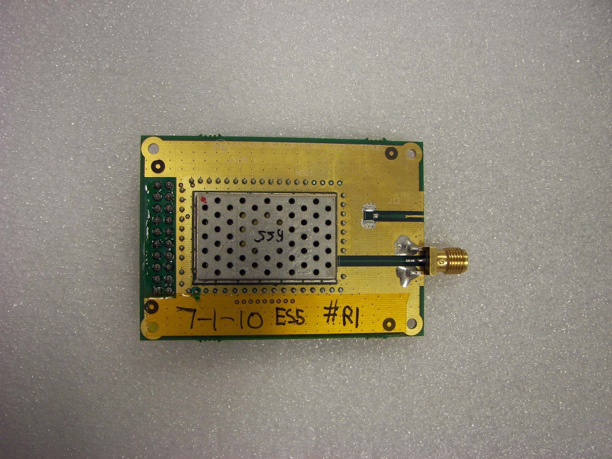
Click to zoom
Application Details
- Equipment Class
- NII - Unlicensed National Information Infrastructure TX
- Date of Grant
- Jan 11, 2011
- Application Purpose
- Original Equipment
- Date of Application
- Jan 11, 2011
- Equipment Note
- RC12
- Frequency Range
- 5500.00000000 - 5700.00000000
- Country
- United States
Documents & Files
Document Text
Text extracted from the exhibit documents filed with the FCC. Open a document above to read the original.
Users Manual
Important RC12 Radio Information! 802.11 Users 802.11 用户 802.11 使用者 Utilisateurs du 802.11 Caution: This marking indicates that the user should read all included documentation before use. Retain this supplement for future reference. Caution: Users of this product are cautioned to use accessories and peripherals approved by Intermec Technologies Corporation. The use of accessories other than those recommended, or changes to the product that is not approved by Intermec Technologies Corporation, may void the compliance of this product and may result in the loss of the user’s authority to operate the equipment. Caution: Users are responsible for configuring the channels of operation that comply with their country regulatory standards. Wireless Network Administrator should review the operating restrictions detailed within the Access Point installation manual. 注意:该标记指示在使用之前用户应阅读所有包含的文档。请保留这份补充材料,以备日后参考。 注意:敬告本产品的用户,请务必使用 Intermec Technologies Corporation 许可的附件和外围设备。 如果使用推荐附件之外的其 它附件,或未经 Intermec Technologies Corporation 许可而擅自改装本产品,都可能会使本产品的符合性无效,并可能会导致用 户失去操作本设备的权利。 注意:用户负责根据所在国家 / 地区的法规标准配置操作信道。无线网络管理员必须仔细阅读 《接入点安装手册》中有关操 作限制的详细信息。 注意:此標誌表示使用者應在使用前先閱讀所有隨附的文件。 請保留這份補充材料,以備日後參考。 注意: 本產品的使用者必須小心使用 Intermec Technologies Corporation 許可的配件與週邊設備。使用非上述建議的配件,或是 在未經 Intermec Technologies Corporation 許可的情況下變更本產品可能會使得本產品的相容性失效,並且使得使用者喪失操作 設備的權力。 注意:使用者負責根據所在國家/地區的法規標準配置操作通道。無線網路管理員必須檢閱《接入點安裝手冊》內有關操作 限制的詳細資訊。 Attention: Ce marquage indique que l’usager doit, avant l’utilisation, lire toute la documentation incluse. Conservez ce supplément pour référence future. Attention: Utilisateurs de ce produit sont avisés d’utiliser des accessoires et des périphériques approuvés par Intermec Technologies Corporation. L’utilisation d’accessoires autres que ceux recommandés ou des changements à ce produit qui ne sont pas approuvés par Intermec Technologies Corporation peuvent annuler la conformité de ce produit et mettre fin au droit qu’a l’usager d’utiliser l’équipement. Attention: Il incombe aux utilisateurs de configurer les canaux de fonctionnement de manière à ce qu’ils se conforment aux normes réglementaires de leur pays. L’administrateur du réseau sans fil doit revoir les restrictions de fonctionnement indiquées en détail au manuel d’installation du point d’accès. Vorsicht: Diese Kennzeichnung weist darauf hin, dass der Benutzer vor dem Gebrauch alle mitgelieferten Unterlagen lesen soll. Diese Ergänzung muss zur zukünftigen Bezugnahme aufgehoben werden. Vorsicht: Die Benutzer dieses Produkts werden darauf hingewiesen, nur Zubehörteile und Peripheriegeräte zu verwenden, die von Intermec Technologies Corporation genehmigt sind. Falls nicht empfohlene Zubehörteile verwendet oder an diesem Produkt Änderungen vorgenommen werden, die nicht von Intermec Technologies Corporation genehmigt sind, kann dadurch die behördliche Konformität des Produkts verletzt werden und der Benutzer die Berechtigung zur Verwendung des Geräts verlieren. 802.11 Benutzer 802.11 사용자 Usuários do 802,11 Пользователи оборудования, соответствующего стандарту 802.11 Usuarios de 802.11 Vorsicht: Benutzer sind dafür verantwortlich, die Betriebskanäle zu konfigurieren, die mit den behördlichen Normen ihres Landes konform sind. Der Verwalter des Drahtlosnetzwerks muss die Betriebsbeschränkungen prüfen, die im Zugriffsstellen-Installationshandbuch beschrieben sind. 주의:이 표시는 제품 사용 전에 모든 설명서 내용을 읽어야 한다는 것을 나타냅니다. 향후 참고를 위해 본 자료를 보관하십 시오. 주의: Intermec Technologies Corporation에서 승인한 부속품 및 주변 기기를 사용하는 본 제품의 사용자는 주의를 기울여 야 합니다. 권장되지 않은 부속품을 사용하거나 Intermec Technologies Corporation의 승인 없이 본 제품을 변경할 경우, 본 제품의 보증이 무효화되거나 장비 조작에 대한 사용자의 권한이 박탈될 수 있습니다. 주의: 사용자는 해당 국가의 규정 기준을 준수하는 작동 채널 구성에 대한 책임이 있습니다. 무선네크워크 관리자는 액세스 포인트 설치 매뉴얼 내에 상세히 기술된 작동 제한규정을 검토해야 합니다. Cuidado: Esta identificação indica que o usuário deve ler toda a documentação fornecida antes do uso. Guarde esse suplemento para referências futuras. Cuidado: Os usuários deste produto devem usar acessórios e periféricos aprovados pela Intermec Technologies Corporation. Usar acessórios não recomendados, ou fazer alterações neste produto não aprovadas pela Intermec Technologies Corporation, poderá anular a conformidade deste produto e resultar na perda da permissão do usuário de utilizar o equipamento. Cuidado: Os usuários são responsáveis pela configuração dos canais de funcionamento que atendem aos padrões regulatórios dos seus países. O administrador de rede sem fio deve analisar as restrições operacionais detalhadas no manual de instalação do ponto de acesso. Осторожно: Эта пометка означает, что пользователь должен прочитать всю прилагаемую документацию, прежде чем начинать работу. Сохраните это дополнение для последующих справок. Осторожно: Пользователи этого продукта предупреждаются, что они должны использовать принадлежности и периферийные устройства, утвержденные Intermec Technologies Corporation. Использование принадлежностей, не являющихся рекомендованными, или внесение в этот продукт изменений, не утвержденных Intermec Technologies Corporation, может сделать продукт не соответствующим требованиям и привести к утрате пользователем права работать с данным оборудованием. Осторожно: Пользователи должны сконфигурировать рабочие каналы в соответствии с регулятивными стандартами своей страны. Администратор беспроводной сети должен учесть рабочие ограничения, подробно перечисленные в руководстве по установке пункта доступа. Precaución: Esta marca indica que el usuario debe leer toda la documentación incluida antes del uso. Retenga este suplemento para referencia futura. Precaución: Se advierte a los usuarios de este producto que usen accesorios y periféricos aprobados por Intermec Technologies Corporation. El uso de accesorios aparte de los recomendados, o los cambios a este producto que no estén aprobados por Intermec Technologies Corporation, pueden anular el cumplimiento de este producto y ocasionar la pérdida de la autorización del usuario para operar el equipo. Precaución: Los usuarios son responsables…
Text truncated - open the document above for the full version.
Cover Letter(s)
Northwest EMC TCB Compliance Opinion Rev. 12/08/09 INMC0575 Information about the Applicant Grantee (Company Name) Intermec Technologies Corporation FCC Contact Person Dave Fry Address 6001 36th Avenue West City, State, Zip Everett, WA 98203-1264 Job Number INMC0575 Model RC12 FCC ID EHA-RC12 Agent Wayne Rieger Approval Type Original Equipment Class DTS Digital Transmission System NII Unlicensed National Information Infrastructure Tx Rule Part 15.247, 15.407 (15C) Overview This application is for an original filing of Intermec Technologies Corporation's radio model RC12, FCC ID: EHA-RC12. The device is a combination 802.11a\b\g\n and Bluetooth radio module. Exhibits have been submitted in support of a full modular approval as a DTS device under 47 Cfr 15.247 and as a UNII device under 47 Crf 15.407. Confidentiality requested for allowed files. Request is properly addressed and referenced. A letter listing the applicable modular requirements was submitted. Recommendation All items have been resolved and completed to my satisfaction; therefore I recommend this application for approval. Signature Dave Tolman, TCB Committee 1/3/2011
Cover Letter(s)
Date: August 16, 2010 Agent’s Authorization Letter To whom it may concern, I, the undersigned, hereby authorize Wayne Rieger, Lead Engineer, Intermec Technologies Corp. to act on my behalf, as our agent, in the following matters related to the regulatory approval of our products: report submittal, related correspondence, the signing of all documents relating to these matters, and any other lawful activity necessary to obtain such certifications. Any act carried out by Wayne Rieger within the scope of this authorization shall have the same affect as our own. I certify that no party (as defined in 47 CFR 1.2002) to this application, including myself, is subject to a denial of federal benefits, that include FCC benefits, pursuant to section 5301 of the Anti-Drug Abuse Act of 1988, 21 U.S.C., 853A. This authorization shall expire 24 months from original date. Certified By: Dave Fry Sr. EMC Engineer 550 Second Street Cedar Rapids, IA 52401 Dave Fry MS GR05 Sr. EMC Engineer tel 319.846.2415 fax 319.846.2475 [email protected] www.intermec.com
Cover Letter(s)
Dec 15, 2010 Federal Communications Commission Authorization and Evaluation Division 7435 Oakland Mills Road Columbia, Maryland 21046 Subject: Modular Approval FCC ID: EHA-RC12 Dear Application Examiner: Intermec Technologies Corporation is submitting an application for certification of the Model RC12 radio, FCC ID: EHA-RC12. It is a combination 802.11a/b/g/n and Bluetooth radio module. Modular approval is sought as a DTS device under FCC 15.247 and as a UNII device under FCC 15.407. The RC12 radio module will only be used 20 cm or greater from the user, so it can be classified as a mobile device per FCC 2.1091. MPE estimates have been provided as part of this application. The RC12 radio module can operate in the DFS frequency bands as a client device only. It has no radar detection and no ad-hoc capability. A DFS test for a client device was performed. The RC12 radio module will only be installed by Intermec into their devices. The antenna connection is not user accessible and therefore meets the requirements of FCC 15.203. Your efforts in reviewing this application are greatly appreciated. Please contact me by telephone at (425) 267-2919 or by e-mail ([email protected]) if there are questions or additional information needed concerning this request. Sincerely, Wayne F. Rieger Radio Compliance Engineer Intermec Technologies Corporation 6001 36 th Avenue West Everett, WA 98203-1264 425-267-2919 6001 36 th Avenue West Everett, Washington 98203 United States tel 425.348.2600 fax 425.355.9551 www.intermec.com
Cover Letter(s)
Dec 15, 2010 Subject: Modular Approval FCC ID: EHA-RC12 Dear Application Examiner: Intermec Technologies Corporation is submitting an application for certification of the Model RC12 radio, FCC ID: EHA-RC12. It is a combination 802.11a/b/g/n and Bluetooth radio module. Modular approval is sought as a DTS device under FCC 15.247 and as a UNII device under FCC 15.407. The radio meets the requirements for modular approval as detailed in FCC 15.212. Compliance to each of the requirements is described below: 1. “The modular transmitter must have its own RF shielding.” The radio portion of the module is contained in its own RF shielding. The shielding is installed at the factory. Please see the Internal Photos exhibit. 2. “The modular transmitter must have buffered modulation/data inputs.” The EUT has buffered data inputs to insure compliance with Part 15 requirements under conditions of excessive data rates or over-modulation. Please see the Schematics exhibit. 3. “The modular transmitter must have its own power supply regulation.” The EUT has its own power supply regulation to insure compliance with Part 15 requirements regardless of the quality or level of external DC supplying the module from the host unit. Please see Schematics exhibit. Also, the technical report exhibit contains AC power line conducted emissions data taken with the EUT powered from a linear power supply that contains no EMC suppression components. 4. “The modular transmitter must comply with the antenna requirements of Section 15.203 and 15.204(c).” The EUT meets the FCC antenna requirements. Please see Antenna information exhibit and internal photos exhibit. 5. “The modular transmitter must be tested in a stand-alone configuration.” The EUT was tested in a stand-alone configuration. The module was greater than 10 cm from the host device. Please see test setup photos exhibit and technical report exhibit. 6. “The modular transmitter must be labeled with its own FCC ID number.” The EUT is labeled with its own FCC ID number. Please see FCC ID label & location exhibit. Since the FCC ID number will not be visible when the module is installed inside a host device, another label with the FCC ID will be applied to the exterior of the host device. 7. “The modular transmitter must comply with any specific rule or operating requirements applicable to the transmitter and the manufacturer must provide adequate instructions along with the module to explain any such requirements.” The EUT is compliant with all applicable FCC rules. Detail instructions for maintaining compliance are given in the User Manual. 8. “The modular transmitter must comply with any applicable RF exposure requirements.” The EUT is compliant with all applicable RF exposure requirements. Please see RF Exposure Exhibit. 6001 36 th Avenue West Everett, Washington 98203 United States tel 425.348.2600 fax 425.355.9551 www.intermec.com Please contact me if you have additional questions. Your attention to this matter is greatly appreciated. Best regards, Wayne F. Rieger Radio Compliance Engineer Intermec Technologies Corporation 6001 36 th Avenue West Everett, WA 98203-1264 425-267-2919
Cover Letter(s)
Federal Communications Commission 7435 Oakland Mills Road Columbia MD 21046 Subject: Request for Confidentiality FCC ID: EHA-RC12 To Whom It May Concern: Pursuant to the provisions of Sections 0.457 and 0.459 of the Commission’s rules (47 CFR §§ 0.457, 0.459), we are requesting the Commission to withhold the following attachments as confidential documents from public disclosure indefinitely. Schematic Diagrams Block Diagram Operational Description The above mentioned documents contain detailed system and equipment information that are considered as proprietary information in operation of the equipment. The public disclosure of above documents might be harmful to our company and would give competitor an unfair advantage in the market. Best regards, Wayne F. Rieger Radio Compliance Engineer Intermec Technologies Corporation 6001 36 th Avenue West Everett, WA 98203-1264 425-267-2919 6001 36 th Avenue West Everett, Washington 98203 United States tel 425.348.2600 fax 425.355.9551 www.intermec.com
ID Label/Location Info
EHA-RC12 RC12 234-103-0001 FCC LABEL(355-485-001) PLACEMENT REFERENCE ONLY NOT TO SCALE EHA-RC12 RC12 234-103-0001
Operational Description
Intermec Radio Group Antenna Measurement System Manufacturer: Intermec Model No: Laird WLAN antenna Serial No: Galileo Modular Approval Operator: Paul Hulett Comments: Laird PIFA antenna for Galileo Approval Baseline Test Method: Two-Axis Dual-Polarization Pattern Measurement Type: WLAN Summary Page Total Frequency (MHz) 2300 2325 2350 2375 2400 2425 Peak Gain (dBi) -3.49576 -2.64318 -2.20726 -0.507975 0.171028 2.43678 Average Gain (dB) -6.83922 -6.39714 -5.47979 -4.22875 -3.82518 -2.21041 Efficiency (%) 20.7051 22.9238 28.3153 37.7681 41.446 60.1117 Upper Hem. PRP (dBm) -10.1195 -9.70152 -8.71557 -7.33266 -6.84438 -5.21584 Boresight Phi (°) 75 15 330 75 15 0 Boresight Th. (°) 135 120 120 120 120 120 Max/Min Ratio (dB) 14.4389 18.0991 19.1496 18.2286 15.4744 14.4571 Total Frequency (MHz) 2450 2475 2500 4850 4900 4925 Peak Gain (dBi) 1.85024 1.18812 -0.233622 1.31029 1.79728 1.61174 Average Gain (dB) -1.66713 -2.09052 -3.2586 -3.52863 -2.98023 -3.23889 Efficiency (%) 68.122 61.7942 47.2215 44.3749 50.3474 47.4363 Upper Hem. PRP (dBm) -4.60572 -4.96963 -6.08939 -6.43522 -5.874 -6.13617 Boresight Phi (°) 345 345 345 45 15 15 Boresight Th. (°) 120 120 120 90 135 135 Max/Min Ratio (dB) 13.8048 13.8619 13.2342 13.2342 17.391 17.4641 Total Frequency (MHz) 4850 4975 5000 5025 5050 5075 Peak Gain (dBi) 2.4412 3.89811 4.49693 4.11994 4.04388 3.73169 Average Gain (dB) -2.52978 -1.15146 -0.682948 -1.15055 -1.2724 -1.43162 Efficiency (%) 55.8498 76.7104 85.4487 76.7265 74.6037 71.9181 Upper Hem. PRP (dBm) -5.42995 -4.01286 -3.5524 -3.99865 -4.13528 -4.31787 Boresight Phi (°) 60 60 60 60 60 45 Boresight Th. (°) 135 135 135 135 135 90 Max/Min Ratio (dB) 17.4089 17.0954 17.0365 17.5987 18.0331 18.3501 Total Frequency (MHz) 5100 5200 5300 5400 5500 5600 Peak Gain (dBi) 4.30265 4.81228 3.92892 3.511 3.77673 3.7525 Average Gain (dB) -1.08138 -0.7122 -1.65632 -2.24108 -2.21636 -2.49938 Efficiency (%) 77.9583 84.875 68.2917 59.6887 60.0294 56.2422 Upper Hem. PRP (dBm) -3.96965 -3.59016 -4.51432 -5.1477 -5.08303 -5.38802 Boresight Phi (°) 45 45 45 45 45 45 Boresight Th. (°) 90 90 90 90 105 105 Max/Min Ratio (dB) 18.3501 19.2517 20.4718 20.2893 23.4335 21.2676 Total Frequency (MHz) 5700 5825 5900 6000 Peak Gain (dBi) 3.46474 3.69245 2.15643 2.10981 Average Gain (dB) -3.16698 -3.12921 -4.17497 -3.74524 Efficiency (%) 48.2284 48.6495 38.2387 42.2159 Upper Hem. PRP (dBm) -6.15028 -6.24897 -7.30164 -6.97168 Boresight Phi (°) 45 45 45 45 Boresight Th. (°) 105 105 105 105 Max/Min Ratio (dB) 20.1208 25.0014 17.8412 17.154 Cut 15 mm from this end of the PCB. I used a 1.74K KOA resistor and a1.5pf Johanson Cap both 0204 P.H. WAN Free-Space Total EIRP, 2400MHz Tot a l EIRP, Right Side Vie w EIRP (dBm) -30 5 -25 -20 -15 -10 -5 0 X Z Y Azimuth = 90.0 Elevation = -90.0 Roll = -90.0 Total EIRP, Left Side View EIRP (dBm) -30 5 -25 -20 -15 -10 -5 0 YX Z Azimuth = 0.0 Elevation = 90.0 Roll = 0.0 Total EIRP, Bottom View EIRP (dBm) -30 5 -25 -20 -15 -10 -5 0 Z X Y Azimuth = -180.0 Elev ation = -1.0 Roll = -179.0 Total EIRP, Top View EIRP (dBm) -30 5 -25 -20 -15 -10 -5 0 X Y Z Azimuth = 0.0 Elevation = 0.0 Roll = 0.0 Tot a l EI RP , Fr ont Fa c e V i e w EIRP (dBm) -30 5 -25 -20 -15 -10 -5 0 Y Z X Azimuth = 90.0 Elevation = 0.0 Roll = -90.0 Total EIRP, Back Face View EIRP (dBm) -30 5 -25 -20 -15 -10 -5 0 XY Z Azimuth = -90.0 Elev ation = 0.0 Roll = 90.0 WAN Free-Space Total EIRP, 2425MHz Tot a l EIRP, Right Side Vie w EIRP (dBm) -30 5 -25 -20 -15 -10 -5 0 X Z Y Azimuth = 90.0 Elev ation = -90.0 Roll = -90.0 Total EIRP, Left Side View EIRP (dBm) -30 5 -25 -20 -15 -10 -5 0 YX Z Azi muth = 0 . 0 Elevation = 90.0 Roll = 0.0 Total EIRP, Bottom View EIRP (dBm) -30 5 -25 -20 -15 -10 -5 0 Z X Y Azimuth = -180.0 Elevation = -1.0 Roll = -179.0 Total EIRP, Top View EIRP (dBm) -30 5 -25 -20 -15 -10 -5 0 X Y Z Azimuth = 0.0 Elev ation = 0.0 Roll = 0.0 Total EIRP, Front Face View EIRP (dBm) -30 5 -25 -20 -15 -10 -5 0 Y Z X Azimuth = 90.0 Elev ation = 0.0 Roll = -90.0 Total EIRP, Back Face View EIRP (dBm) -30 5 -25 -20 -15 -10 -5 0 XY Z Azimuth = -90.0 Elev ation = 0.0 Roll = 90.0 WAN Free-Space Total EIRP, 2450MHz Tot a l EIRP, Right Side Vie w EIRP (dBm) -30 5 -25 -20 -15 -10 -5 0 X Z Y Azimuth = 90.0 Elev ation = -90.0 Roll = -90.0 Total EIRP, Left Side View EIRP (dBm) -30 5 -25 -20 -15 -10 -5 0 YX Z Azimuth = 0.0 Elevation = 90.0 Roll = 0.0 Total EIRP, Bottom View EIRP (dBm) -30 5 -25 -20 -15 -10 -5 0 Z X Y Azimuth = -180.0 Elevation = -1.0 Roll = -179.0 Total EIRP, Top View EIRP (dBm) -30 5 -25 -20 -15 -10 -5 0 X Y Z Azimuth = 0.0 Elev ation = 0.0 Roll = 0.0 Total EIRP, Front Face View EIRP (dBm) -30 5 -25 -20 -15 -10 -5 0 Y Z X Azimuth = 90.0 Elev ation = 0.0 Roll = -90.0 Total EIRP, Back Face View EIRP (dBm) -30 5 -25 -20 -15 -10 -5 0 XY Z Azimuth = -90.0 Elev ation = 0.0 Roll = 90.0 WAN Free-Space Total EIRP, 2475MHz Tot a l EIRP, Right Side Vie w EIRP (dBm) -30 5 -25 -20 -15 -10 -5 0 X Z Y Azimuth = 90.0 Elev ation = -90.0 Roll = -90.0 Total EIRP, Left Side View EIRP (dBm) -30 5 -25 -20 -15 -10 -5 0 YX Z Azimuth = 0.0 Elevation = 90.0 Roll = 0.0 Total EIRP, Bottom View EIRP (dBm) -30 5 -25 -20 -15 -10 -5 0 Z X Y Azimuth = -180.0 Elevation = -1.0 Roll = -179.0 Total EIRP, Top View EIRP (dBm) -30 5 -25 -20 -15 -10 -5 0 X Y Z Azimuth = 0.0 Elev ation = 0.0 Roll = 0.0 Total EIRP, Front Face View EIRP (dBm) -30 5 -25 -20 -15 -10 -5 0 Y Z X Azimuth = 90.0 Elevation = 0.0 Roll = -90.0 Total EIRP, Back Face View EIRP (dBm) -30 5 -25 -20 -15 -10 -5 0 XY Z Azimuth = -90.0 Elevation = 0.0 Roll = 90.0 WAN Free-Space Total EIRP, 2500MHz Tot a l EIRP, Right Side Vie w EIRP (dBm) -30 0 -25 -20 -15 -10 -5 X Z Y Azimuth = 90.0 Elev ation = -90.0 Roll = -90.0 Total EIRP, Left Side View EIRP (dBm) -30 0 -25 -20 -15 -10 -5 YX Z Azi muth = 0 . 0 Elevation = 90.0 Roll = 0.0 Total EIRP, Bottom View EIRP (dBm) -30 0 -25 -20 -15 -10 -5 Z X Y Azimuth = -180.0 Elev ation = -1.0 Roll = -179.0 Total EIRP, Top View EIRP (dBm) -30 0 -25 -20 -15 -10 -5 X Y Z Azimuth …
Text truncated - open the document above for the full version.
RF Exposure Info
Antenna T ype Ant enna M an ufa ct urer Antenna Part No. Transmit Freq uency Ma x Pea k Conducted Ou tput Power Antenna Gain M i n i mu m An t e n n a Cable Loss Powe r Density @ 20 cm General Pop ula ti on Exposure Limit from 1.1310 (MHz)( mW)( dBi)(dB) (mW/cm 2 )(mW/cm 2 ) PIFALaird Laird WLAN240053.22.400.018392541 PIF ALairdLaird WLAN520025.14.800.015080091 FCC ID: EHA-RC12 Compliance with 47 CFR 2.1091 and 1.1310 The EUT is a combination 802.11a/b/g/n and Bluetooth radio module. The EUT will only be used with a separation distance of 20 centimeters or greater between the antenna and the body of the user or nearby persons and can therefore be considered a mobile transmitter per 47 CFR 2.1091(b). The antenna is a PIFA with a peak gain of 2.4 dBi in the 2.4 GHz band, and 4.8 dBi in the 5 GHz band. The maximum peak conducted output power is 53mW in the 2.4 GHz band, and 25 mW in the 5 GHz band. The maximum peak radiated power is 92 mW (EIRP) for FCC ID: EHA-RC12. The transmit frequencies are in the 2.4 and 5 GHz bands Since the transmit frequency is more than 1.5 GHz, and the output power is less than 3.0 W ERP, the EUT is categorically excluded from routine environmental evaluation per 47 CFR 2.1091(c). The MPE estimates are as follows: Table 1 in 47 CFR 1.1310 defines the maximum permissible exposure (MPE) for the general population as 1 mW/cm 2 . The exposure level at a 20 cm distance from the EUT’s transmitting antenna is calculated using the general equation: S = (PG)/4R 2 Where: S = power density (mW/cm 2 ) P = power input to the antenna (mW) G = numeric power gain relative to an isotropic radiator R = distance to the center of the radiation of the antenna (20 cm = limit for MPE estimates) PG = EIRP Solving for S, the maximum power density 20 cm from the transmitting antenna is summarized in the following table: The power density does not exceed 0.018 mW/cm 2 at 20 cm; therefore, the exposure condition is compliant with FCC rules.
Test Report
Intermec Technologies Corporation Model: RC12 Tested to the following Specifications: FCC 15.247:2010 FCC 15.207:2010 Report No. INMC0575 Report Prepared By www.nwemc.com 1-888-EMI-CERT © 2010 Northwest EMC, Inc 22975 NW Evergreen Parkway Suite 400 Hillsboro, Oregon 97124 Certificate of Test Last Date of Test: August 11, 2010 Intermec Technologies Corporation Model: RC12 Emissions Test Description Specification Test Method Pass/Fail Occupied Bandwidth FCC 15.247:2010 ANSI C63.10:2009 Pass Output Power – Channel Power FCC 15.247:2010 ANSI C63.10:2009 Pass Band Edge Compliance FCC 15.247:2010 ANSI C63.10:2009 Pass Spurious Conducted Emissions FCC 15.247:2010 ANSI C63.10:2009 Pass Power Spectral Density FCC 15.247:2010 ANSI C63.10:2009 Pass Spurious Radiated Emissions FCC 15.247:2010 ANSI C63.10:2009 Pass AC Powerline Conducted Emissions FCC 15.207:2010 ANSI C63.10:2009 Pass Modifications made to the product See the Modifications section of this report Test Facility The measurement facility used to collect the data is located at: Northwest EMC, Inc. 22975 NW Evergreen Parkway, Suite 400 Hillsboro, OR 97124 Phone: (503) 844-4066 Fax: 844-3826 This site has been fully described in a report filed with and accepted by the FCC (Federal Communications Commission) and Industry Canada (Site filing #2834D-2). Approved By: Don Facteau, IS Manager NVLAP Lab Code: 200630-0 This report must not be used to claim product certification, approval, or endorsement by NVLAP, NIST, or any agency of the federal government of the United States of America. Product compliance is the responsibility of the client, therefore the tests and equipment modes of operation represented in this report were agreed upon by the client, prior to testing. This Report may only be duplicated in its entirety. The results of this test pertain only to the sample(s) tested. The specific description is noted in each of the individual sections of the test report supporting this certificate of test. Northwest EMC Revision History Revision 06/29/09 Barometric Pressure The recorded barometric pressure has been normalized to sea level. Revision Number Description Date Page Number 00 None Accreditations and Authorizations FCC Accredited by NVLAP for performance of FCC radio, digital, and ISM device testing. Our Open Area Test Sites, certification chambers, and conducted measurement facilities have been fully described in reports filed with the FCC and accepted by the FCC in letters maintained in our files. Northwest EMC has been accredited by ANSI to ISO / IEC Guide 65 as a product certifier. We have been designated by the FCC as a Telecommunications Certification Body (TCB). This allows Northwest EMC to certify transmitters to FCC specifications in accordance with 47 CFR 2.960 and 2.962. NVLAP Northwest EMC, Inc. is accredited under the United States Department of Commerce, National Institute of Standards and Technology, and National Voluntary Laboratory Accreditation Program for satisfactory compliance with the requirements of ISO/IEC 17025 for Testing Laboratories. The NVLAP accreditation encompasses Electromagnetic Compatibility Testing in accordance with the European Union EMC Directive 2004/108/EC, and ANSI C63.4. Additionally, Northwest EMC is accredited by NVLAP to perform radio testing in accordance with the European Union R&TTE Directive 1999/5/EEC, the requirements of FCC, and the RSS radio standards for Industry Canada. NVLAP LAB CODE 200629-0 NVLAP LAB CODE 200630-0 NVLAP LAB CODE 200676-0 NVLAP LAB CODE 200761-0 NVLAP LAB CODE 200881-0 Industry Canada Accredited by NVLAP for performance of Industry Canada RSS and ICES testing. Our Open Area Test Sites and certification chambers comply with RSS-Gen, Issue 2 and have been filed with Industry Canada and accepted. Northwest EMC has been accredited by ANSI to ISO / IEC Guide 65 as a product certifier. We have been designated by NIST and recognized by Industry Canada as a Certification Body (CB) per the APEC Mutual Recognition Arrangement (MRA). This allows Northwest EMC to certify transmitters to Industry Canada technical requirements. (Site Filing Numbers - Hillsboro: 2834D-1, 2834D-2, Sultan: 2834C-1, Irvine: 2834B-1, 2834B-2, Brooklyn Park: 2834E-1) CAB Designated by NIST and validated by the European Commission as a Conformity Assessment Body (CAB) to conduct tests and approve products to the EMC directive and transmitters to the R&TTE directive, as described in the U.S. - EU Mutual Recognition Agreement. NEMKO Assessed and accredited by NEMKO (Norwegian testing and certification body) for European emissions and immunity testing. As a result of NEMKO's laboratory assessment, they will accept test results from Northwest EMC, Inc. for product certification (Authorization No. ELA 119). Accreditations and Authorizations Australia/New Zealand The National Association of Testing Authorities (NATA), Australia has been appointed by the ACA as an accreditation body to accredit test laboratories and competent bodies for EMC standards. Accredited test reports or assessments by competent bodies must carry the NATA logo. Test reports made by an overseas laboratory that has been accredited for the relevant standards by an overseas accreditation body that has a Mutual Recognition Agreement (MRA) with NATA are also accepted as technical grounds for product conformity. The report should be endorsed with the respective logo of the accreditation body (NVLAP). VCCI Accepted as an Associate Member to the VCCI, Acceptance No. 564. Conducted and radiated measurement facilities have been registered in accordance with Regulations for Voluntary Control Measures, Article 8. (Registration Numbers. - Hillsboro: C-1071, R-1025, G-84, C-2687, T-1658, and R-2318, Irvine: R-1943, G-85, C- 2766, and T-1659, Sultan: R-871, G-83, C-1784, and T-1511, Brooklyn Park: R-3125, G-86, G-141, C-3464, and T-1634). BSMI Northwest EMC has been designated by NIST and validated by C-Taipei (BSMI) as a CAB to conduct tests as des…
Text truncated - open the document above for the full version.
Test Report
Intermec Technologies Corporation Model: RC12 Tested to the following Specifications: FCC 15.247:2010 FCC 15.207:2010 Report No. INMC0575.1 Report Prepared By www.nwemc.com 1-888-EMI-CERT © 2010 Northwest EMC, Inc 22975 NW Evergreen Parkway Suite 400 Hillsboro, Oregon 97124 Certificate of Test Last Date of Test: August 11, 2010 Intermec Technologies Corporation Model: RC12 Emissions Test Description Specification Test Method Pass/Fail Occupied Bandwidth FCC 15.247:2010 ANSI C63.10:2009 Pass Output Power FCC 15.247:2010 ANSI C63.10:2009 Pass Band Edge Compliance FCC 15.247:2010 ANSI C63.10:2009 Pass Spurious Conducted Emissions FCC 15.207:2010 ANSI C63.10:2009 Pass Power Spectral Density FCC 15.247:2010 ANSI C63.10:2009 Pass Spurious Radiated Emissions FCC 15.247:2010 ANSI C63.10:2009 Pass AC Powerline Conducted Emissions FCC 15.247:2010 ANSI C63.10:2009 Pass Modifications made to the product See the Modifications section of this report Test Facility The measurement facility used to collect the data is located at: Northwest EMC, Inc. 22975 NW Evergreen Parkway, Suite 400 Hillsboro, OR 97124 Phone: (503) 844-4066 Fax: 844-3826 This site has been fully described in a report filed with and accepted by the FCC (Federal Communications Commission) and Industry Canada (Site filing #2834D-2). Approved By: Don Facteau, IS Manager NVLAP Lab Code: 200630-0 This report must not be used to claim product certification, approval, or endorsement by NVLAP, NIST, or any agency of the federal government of the United States of America. Product compliance is the responsibility of the client, therefore the tests and equipment modes of operation represented in this report were agreed upon by the client, prior to testing. This Report may only be duplicated in its entirety. The results of this test pertain only to the sample(s) tested. The specific description is noted in each of the individual sections of the test report supporting this certificate of test. Northwest EMC Revision History Revision 0…
Text truncated - open the document above for the full version.
Contact Information
Applicant
Brian Rudick(VP & GC, Honeywell Scanning & Mobility)
Test Firm
Northwest EMC, Inc.Greg Kiemel
Technical Specifications
| # | Rule Parts | Frequency Range | Power Output |
|---|---|---|---|
| 3 | 15E | 5.50 GHz - 5.70 GHz | 19.50 mW |
Other Applications from Intermec Technologies Corporation
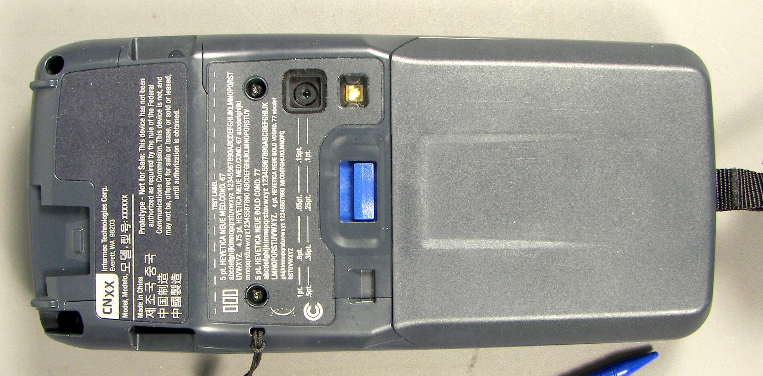
EHA-1015CP01X1
Sep 29, 20131015CP01
Equipment Class
NII - Unlicensed National Information Infrastructure TX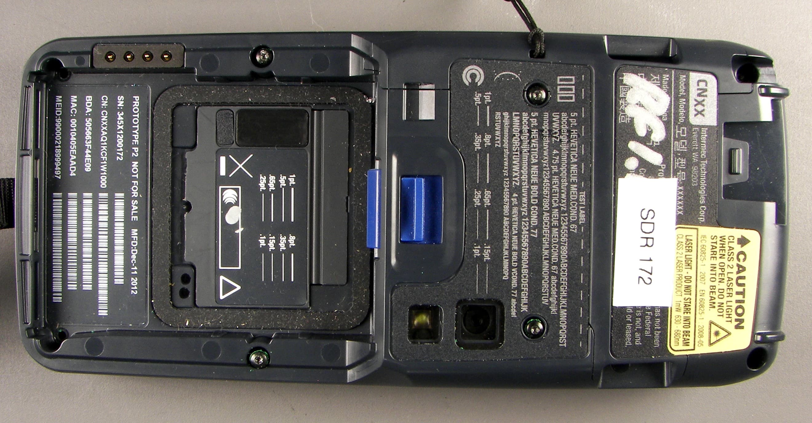
EHA-1015CP01SX1
Sep 08, 20131015CP01S
Equipment Class
PCE - PCS Licensed Transmitter held to ear
EHA-RC12ABGN
Aug 19, 2013WLAN board
Equipment Class
DSS - Part 15 Spread Spectrum Transmitter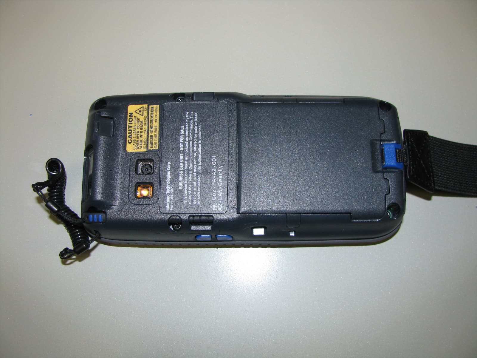
EHA-1000CP01F
Feb 19, 20131000CP01F9, 1000CP02F9, 1001CP01F9
Equipment Class
DTS - Digital Transmission System
EHA-INBT02
Dec 11, 2012BT Board
Equipment Class
DSS - Part 15 Spread Spectrum Transmitter