EHA-RM91501X04RF Tag Reader
Intermec Technologies Corporation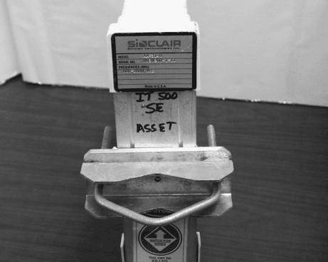
Click to zoom
Application Details
- Equipment Class
- DSS - Part 15 Spread Spectrum Transmitter
- Date of Grant
- Jul 10, 2002
- Application Purpose
- Original Equipment
- Date of Application
- Feb 24, 2002
- Equipment Note
- RF Tag Reader
- Frequency Range
- 902.60000000 - 927.40000000
- Country
- United States
Documents & Files
Document Text
Text extracted from the exhibit documents filed with the FCC. Open a document above to read the original.
Users Manual
ROGERS LABS, INC. Intermec Technologies Corporation 4405 W. 259th Terrace MODEL: ITRM91501X04 Louisburg, KS 66053 Test #: 0200205 FCCID#: EHA-RM91501X04 Phone/Fax: (913) 837-3214 Test to: FCC Parts 2 and 15 Page 1 of 1 RM915Manual.doc 2/12/2002 Compliance Statement Insert Device Name: RF Identification Radio Module Model Number: ITRM91501X04 FCC ID: EHA-RM91501X04 The responsible party for the compliance of this device is: Intermec Technologies Corporation 6001 36 th Avenue West Everett, WA 98203 USA (425) 348-2600 This product conforms to the following approvals. The user(s) of this product are cautioned to use accessories and peripherals approved by Intermec Technologies Corporation. The use of accessories other than those recommended or changes to this product that are not approved by Intermec Technologies Corporation may void the compliance of this product and may result in the loss of the users authority to operate the equipment. This device complies with part 15 of the FCC and Industry Canada Rules. Operation is subject to the following two conditions: (1) This device may not cause harmful interference, and (2) this device must accept any interference received, including interference that may cause undesired operation. FCC Digital Emissions Compliance Note: This equipment has been tested and found to comply with the limits for a Class A digital device, pursuant to part 15 of the FCC Rules. These limits are designed to provide reasonable protection against harmful interference when the equipment is operated in a commercial environment. This equipment generates, uses, and can radiate radio frequency energy and , if not installed and used in accordance with the instruction manual, may cause harmful interference to radio communications. Operation of this equipment is a residential area is likely to cause harmful interference in which case the user will be required to correct the interference at his own expense. Canadian Digital Apparatus Compliance This Class A digital apparatus meets all requirements of the Canadian Interference-Causing Equipment Regulations. Cet appareil numérique de la classe A respecte toutes les exigences du Règlement sur le matériel brouilleur du Canada. WARNING: per the FCC and Canadian RF (radio frequency) exposure requirements, (1) Antennas must be supplied and installed as recommended by Intermec Technologies to ensure compliance to RF exposure requirements. The antennas approved for use are Intermec part numbers 05488-01 and 805-576-002. Correct antenna mounting is fully described within the Intermec ITRM91501X04 Users Guide. (2) When installing and using Intermec approved remote antennas associated the RFID tag reader, a 20-cm (8-inch) passing distance must be maintained from any body part of the user or near by persons and the remote antenna. The antenna must not be touched during transmitter operation. (3) Cables attached to the remote antennas must have a minimum length as provided from Intermec to insure the proper losses to control RF exposure. (4) RF safety requirements mandate this device cannot be co-located with other transmitters. WARNING CANADA USERS: To prevent radio interference to the licensed service, this device is intended to be operated indoors and away from windows to provide maximum shielding. Equipment (or its transmit antenna) that is installed outdoors is subject to licensing. The end user is responsible to obtain the license.
Users Manual
ITRF91501 Reader Quick Start Guide PRELIMINARY EDITION 20 June 02 ITRF91501 Reader Quick Start Guide 2 Packing List WARNING: This is a Class A product. In a domestic environment this product may cause radio interference in which case the user may be required to take adequate measures. Check to ensure that you receive these items: Intermec R ITRF91501 MHz Reader Model Number ITRF91501 (part number country dependent) Product Warranty Card Compliance Statement RF ID 915 MHz 33 x 105 Container Sample Tags p/n ITTP9151002 ITRF91501 Reader Quick Start Guide 3 Host Communication Host communication comes through the 9-pin female D-sub connector. Both RS-232 and RS-422 standards are supported as ordered from the factory or service center Table 1-1 RS-232 Connections Pin Number Definition 2Serial Data from the Fixed Reader to the host 3Serial Data to the Fixed Reader from the host 5Ground 7CTS (Clear to Send) to the Fixed Reader from the host 8RTS (Request to Send) from the Fixed Reader to the host Table 1-2 RS-422 Connections Pin Number Definition 1Serial Data Out + from the Fixed Reader to the host 4Serial Data Out -- from the Fixed Reader to the host 5Ground 6Serial Data In + to the Fixed Reader from the host 9Serial Data In -- to the Fixed Reader from the host The default baud rate is 115.2 kbps with 8 data bits, no parity, and 1 stop bit. ITRF91501 Reader Quick Start Guide 4 Power Requirements Power comes in from 8 to 10 volts DC. The Fixed Reader uses less than 2 amps. Intermec supplies 9 volts DC at 2.4 amps from Intermec power supply, p/n: 351-066-001. User I/O A general purpose I/O (Input/Output) connector provides signal lines in and out of the reader allowing monitoring and/or con- trol of external devices or functions. The connector for this is a 13-pin female circular DIN. The mating male connector you need for mating with this is an In- termec p/nL 351-184-001. Table 1-3 I/O Pin-outs Pin Number Definition 1GPIOIN0 2GPIOIN1 3GPIOIN2 4GPIOIN3 5GPIOOUT0 6GPIOOUT1 7GPIOOUT2 8GPIOOUT3 9, 10, 11, 12, 13 GROUND though individual 10 ohm resistors Outputs and inputs have 12 volt transient suppression devices to ground at the connector. Output signals are driven by 2N3904 NPN transistors (low level) with a 100 kohm pull--up to +5 volts through a silicon diode, giving about a 4.3 volt high level. An output can be pulled high from an external source as high as 40 volts. This will however tend to pull the other out- puts higher (through two 100k resistors). The low level will be about 0.1 volt up to about 30 mA. The output low voltage will ITRF91501 Reader Quick Start Guide 5 climb higher as the sink current increases. There is no protec- tion on this. You need to ensure that their load won’t require thereadertosinkmorethan50mA. Input signals should be 0 to +1.5 volt for a low input and +3.5 to +5 volts for a high input. Each input has a 1.1 kohm resistor in series with clamping diodes, but only about 1μA is used until the input exceeds the 0 to +5 volt input range. There is also a weak (100 kohm) pull--up to +5 volt on each input. Connecting and Getting Started WARNING: FCC regulations limit exposure to radiofrequency (RF) radiation. To comply with these regulations, operators of this device must maintain a distance of at least 23 cm. (9.1 inches) from the cover on the antenna assembly (The cover on the antenna is the dome shaped surface). While the device is on, the operator’s body and parts of the body such as eyes, hands, or head, must be 23 cm. (9.1 inches) or farther from the cover of the antenna assembly. FCC regulations also require that the antenna assembly of this device be installed in accordance with the installation procedures to allow the operator to comply with the limit. Antenna Installation Ensure that you read the above warning before installing the antennas and using your Reader product. ITRF91501 Reader Quick Start Guide 6 Front view of the antenna 1. Review the locations where the Reader products need in- tegrated. Ensure that you have careful considered the safe distances for product placement for workers and any other personnel that may get in the RF path. 2 . Place t he radio and antennas w ith c abling are easily ac - cessible for installation and troubleshooting. 3. Use the mounting bracket to attach the antenna to a fixed surface. 4. Attach the antenna to one of the four antenna ports on the back of the Reader. 5. Do not transmit simultaneously with multiple antennas. ITRF91501 Reader Quick Start Guide 7 The following illustrations are a couple of examples for Reader installations. EXAMPLE 1:Shipping Dock Door, showing two antennas at each shipping door. Two antennas in a crossing pattern provide angular diversity to improve read capability when tag orientation is unknown. WARNING: While the device is on, the operator’s body and parts of the body such as eyes, hands, or head, must be 23 cm. (9.1 inches) or farther from the cover of the antenna assembly. Shipping Door #1Shipping Door #2 100” Max. distance to tag A singular antenna in a portal may be sufficient in applications where there is a known tag orientation. ITRF91501 Reader Quick Start Guide 8 EXAMPLE 2:Two Product Line Conveyers, showing two antennas on each line. Two antennas in a crossing pattern provide angular diversity to improve read capability when tag orientation is unknown. The frames for these stations are PVC tubing with RF reflec- tive Mylar liner X2. Ensure that an 9.1 inch (23 cm) distance from the antenna assembly is maintained to limit people’s ex- posure to radiofrequency (RF) radiation. WARNING: While the device is on, the operator’s body and parts of the body such as eyes, hands, or head, must be 23 cm. (9.1 inches) or farther from the cover of the antenna assembly. Conveyer Belt #1 Conveyer Belt #2 A singular antenna in a portal may be sufficient in applications where there is a known tag orientation. 100” Max. distance to tag ITRF91501 Reader Quick Start Guide 9 Connecting the Antenna to the…
Text truncated - open the document above for the full version.
Users Manual
ROGERS LABS, INC. Intermec Technologies Corporation 4405 W. 259th Terrace MODEL: ITRM91501X04 Louisburg, KS 66053 Test #: 0200205 FCCID#: EHA-RM91501X04 Phone/Fax: (913) 837-3214 Test to: FCC Parts 2 and 15 Page 1 of 1 RM915Manual.doc 2/12/2002 Compliance Statement Insert Device Name: RF Identification Radio Module Model Number: ITRM91501X04 FCC ID: EHA-RM91501X04 The responsible party for the compliance of this device is: Intermec Technologies Corporation 6001 36 th Avenue West Everett, WA 98203 USA (425) 348-2600 This product conforms to the following approvals. The user(s) of this product are cautioned to use accessories and peripherals approved by Intermec Technologies Corporation. The use of accessories other than those recommended or changes to this product that are not approved by Intermec Technologies Corporation may void the compliance of this product and may result in the loss of the users authority to operate the equipment. This device complies with part 15 of the FCC and Industry Canada Rules. Operation is subject to the following two conditions: (1) This device may not cause harmful interference, and (2) this device must accept any interference received, including interference that may cause undesired operation. FCC Digital Emissions Compliance Note: This equipment has been tested and found to comply with the limits for a Class A digital device, pursuant to part 15 of the FCC Rules. These limits are designed to provide reasonable protection against harmful interference when the equipment is operated in a commercial environment. This equipment generates, uses, and can radiate radio frequency energy and , if not installed and used in accordance with the instruction manual, may cause harmful interference to radio communications. Operation of this equipment is a residential area is likely to cause harmful interference in which case the user will be required to correct the interference at his own expense. Canadian Digital Apparatus Compliance This Class A digital apparatus meets all requirements of the Canadian Interference-Causing Equipment Regulations. Cet appareil numérique de la classe A respecte toutes les exigences du Règlement sur le matériel brouilleur du Canada. WARNING: per the FCC and Canadian RF (radio frequency) exposure requirements, (1) Antennas must be supplied and installed as recommended by Intermec Technologies to ensure compliance to RF exposure requirements. The antennas approved for use are Intermec part numbers A270001-02 and A270002-05. Correct antenna mounting is fully described within the Intermec ITRM91501X04 Users Guide. (2) When installing and using Intermec approved remote antennas associated the RFID tag reader, a 23-cm (9.1-inch) passing distance must be maintained from any body part of the user or near by persons and the remote antenna. The antenna must not be touched during transmitter operation. (3) Cables attached to the remote antennas must have a minimum length as provided from Intermec to insure the proper losses to control RF exposure. (4) RF safety requirements mandate this device cannot be co-located with other transmitters. WARNING CANADA USERS: To prevent radio interference to the licensed service, this device is intended to be operated indoors and away from windows to provide maximum shielding. Equipment (or its transmit antenna) that is installed outdoors is subject to licensing. The end user is responsible to obtain the license.
Cover Letter(s)
February 25, 2002 Federal Communications Commission Equipment Approval Services P.O. Box 35815 Pittsburgh, PA 15251-3315 Applicant: Intermec Technologies Corporation 550 2 nd Street SE Cedar Rapids, IA 52401 USA (505) 449-2757 Equipment: FCC ID: EHA-RM91501X04 FCC Rules: Part 15.247 (Frequency Hopping Spread Spectrum Transmitter) Modular Transmitter Gentlemen: The Application for Certification for this frequency hopping spread spectrum transmitter module operated in the 902-928 MHz frequency band under part 15.247 has been completed. The 731 form and certification application have been electronically submitted and any attachments will be up loaded to your web site. Please use this information in obtaining a grant of certification for the transmitter module. As requested in the Public Notice DA00-1407 regarding Part 15 unlicensed modular transmitter approval, the following information has been addressed. The transmitter module is a complete RF transmitter containing its own reference oscillator, antenna etc. The connections available on the module are for power and data inputs only. Below please find information, addressing each paragraph from DA00-1407, requested about the unit. 1.) The unit has its own RF shield to prevent coupling between the RF circuitry of the module and any wires or circuits in the device into which the module is installed. Photographs of the unit are included in an exhibit with the application. 2.) The unit incorporates a buffer stage on the inputs to limit over-modulation. 3.) The unit has power regulation incorporated in the circuitry to ensure continued compliance regardless of the design of the power supplying circuitry. 4.) The unit utilizes a unique coupling to the antenna, which is supplied with the unit. The configuration uses a reverse SMA connection at the board and the two antenna options for this unit connect to this unique port. This fulfills the requirements of 15.203. 5.) The module was tested in a stand-alone configuration. The module complies with part 15 emissions limits regardless of the device into which it is eventually installed. 6.) The module has the FCC ID on a label, which is mounted to the shield of the module, and the end user is supplied with a label and information to affix to the outside of the device, which contains the module. 7.) The unit complies with part 15.247 frequency hopping spread spectrum devices. Adequate instructions are supplied with the unit to explain the requirements. 8.) The unit complies with the RF exposure requirements as stated in 2.1091, 2.1093, and part 15. Please keep the information in confidence, as this applicant has requested confidentiality for the submittal. Should you require any further information, please contact the undersigned. Thank you for your consideration in this matter. Sincerely, Scot Rogers Rogers Labs, Inc. Enclosures ROGERS LABS, INC. 4405 West 259 th Terrace Louisburg, KS 66053 Phone / Fax (913) 837-3214
ID Label/Location Info
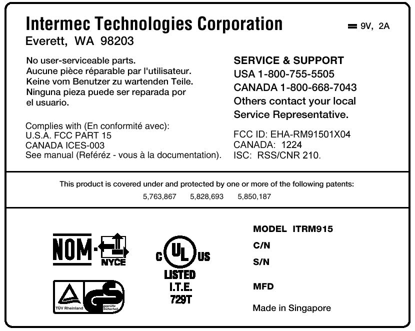
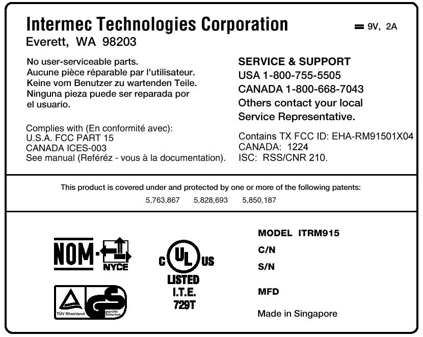
ROGERS LABS, INC. Intermec Technologies Corporation 4405 W. 259th Terrace MODEL: ITRM91501X04 Louisburg, KS 66053 Test #: 0200205 FCCID#: EHA-RM91501X04 Phone/Fax: (913) 837-3214 Test to: FCC Parts 2 and 15 Page 1 of 1 RM915IDLabel.doc 2/12/2002 Photographs of ID Label for module ITRM91501X04. Board Set Label. Serial box label.
Internal Photos
ROGERS LABS, INC. Intermec Technologies Corporation 4405 W. 259th Terrace MODEL: ITRM91501X04 Louisburg, KS 66053 Test #: 0200205 FCCID#: EHA-RM91501X04 Phone/Fax: (913) 837-3214 Test to: FCC Parts 2 and 15 Page 1 of 2 RM915Internal.doc 2/15/2002 Photographs of printed circuit boards and component locations for ITRM91501X04. ROGERS LABS, INC. Intermec Technologies Corporation 4405 W. 259th Terrace MODEL: ITRM91501X04 Louisburg, KS 66053 Test #: 0200205 FCCID#: EHA-RM91501X04 Phone/Fax: (913) 837-3214 Test to: FCC Parts 2 and 15 Page 2 of 2 RM915Internal.doc 2/15/2002 DSP boards
RF Exposure Info
ROGERS LABS, INC. Intermec Technologies Corporation 4405 W. 259th Terrace MODEL: ITRM91501X04 Louisburg, KS 66053 Test #: 020205 FCCID#: EHA-RM91501X04 Phone/Fax: (913) 837-3214 Test to: FCC Parts 2 and 15 Page 1 of 1 ITRM915RFExp.doc 2/11/2002 General The ITRM91501X04 module is a frequency hopping spread spectrum transmitter operating in the frequency band of 902 MHz to 928 MHz with 1 watt of output power into a 3-dBi gain directional antenna. Per table 1 of 1.1307, paragraphs 1.1310 and 2.1093 of CFR 47, evaluation for this device is as follows. Due to the location of the antenna, normal operating conditions and use, the unit will satisfy the requirements for RF Exposure. Calculations are made here for completeness. SPECIFIC ABSORPTION RATE CALCULATION Calculations per 2.1093 of CFR 47. These calculations are based upon a typical human figure as approximated below. The height is 5’ 8” (173 cm.) and the weight is 160 lbs. (72.6kg). The calculated absorption cross section for this figure is 143 cm squared. CALCULATED GENERAL POPULATION/ UNCONTROLLED EXPOSURE SAR Per 1.1310, the requirement for power density in general population/uncontrolled exposure is f/1500, which equates to 0.6 mW/cm 2 calculated for 915 MHz. This amount to be averaged over a time period of 30 minutes. The inherent design of this product would require the antenna to be permanently mounted at a distance much grater than the 20 cm used for this calculation. The 20 cm distance was used to show compliance only. S = PG/(4piR 2 ) Where S = power density in mw/cm 2 ; P = input power to antenna in mw; G = power gain of antenna; and R = distance from antenna in cm; pi = 3.14159. For a minimum distance of 20 centimeters and 1.0 watts (1000 mW) operation with the supplied antenna with a numeric gain of two, S is calculated as 0.3979 mw/cm 2 . S = 1000(2)/(4pi (20) 2 ) = 0.3979 mw/cm 2 Per 2.1093 the limit for general population/Uncontrolled exposure is 0.08W/kg as averaged over the whole body. For a body cross sectional area of 143 cm squared, (0.3979)(143) = 56.898 mw is absorbed. For a body mass of 72.6 kg, this is 56.898/72.6 = 0.783 mw/kg = 0.000783 w/kg. This is well within the 0.08 w/kg limit prescribed for general population/uncontrolled exposure as prescribed by CFR 47 paragraph 2.1093.
RF Exposure Info
A Company June 20, 2002 Intermec Technologies Corporation Systems and Solutions 550 Second Street S.E. Cedar Rapids, IA 52401 Subject: FCC ID: EHA-RM91501X04 Antenna details for Intermec radio model ITRM915. Intermec PN A270001-02 Gain 6-dBi in final worst case configuration. The Sinclair SRL-441U antenna is a 5.5-dBd (7.67-dBi) gain antenna. Intermec will use 13 feet of RG 58 cable to introduce 2.0-dB loss in the antenna path. The net gain of this antenna system will be 5.7-dBi gain. Intermec PN A270002-05 Gain 4-dBi in final worst case configuration. The Cushcraft S9028PC12NF antenna is a 7.5-dBic-gain antenna. Applying a -3 dB linear isolation calculation the antenna has a horizontal or vertical gain of 4.5 dBi. Intermec will use 6 feet of RG 58 cable to introduce 0.7-dB loss in the antenna path. The net gain of this antenna system will be 3.8-dBi gain. Both antennas above will offer cables longer than specified above to accommodate installation variations. Those cables will be of the same type listed above. All antennas will use connectors that meet the unique connector regulations and will NOT have any offering that includes field terminations. Dave Fry Regulatory Engineer Technologies Corporation David L. Fry EMC Test Laboratory Regulatory Engineer Cedar Rapids, IA Date: May 7, 2002 MPE CalculatordBi7.67 dBd + 2.17 = dBidBi to dBd2.17 TX Frequency (MHz)900Watts1Antenna Gain dBd5.5 Cable Losses dB2dBm30.000000Antenna minus cable = dBi5.67 radiated (ERP) dBm33.500 radiated (EIRP) dBm35.670 Ocupational Limit 3.00mW/cm meterscm General Public Limit0.33333333333.333 0.60mW/cm d = cmEIRP=mW occ.limitpublic limit f/300f/1500 51 MPE uses EIRP for calculations. EIRP is based on TX power added to the antenna gain in dBi. dBi = dB gain compared to an isotropic radiator EIRPDistanceDistanceDistance (watts)(cm)(Meters)(inches)mW/cm 3689.776100.001.000039.370.02936 3689.77675.000.750029.530.05220 3689.77650.000.500019.690.11745 3689.77640.000.400015.750.18351 3689.77635.000.350013.780.23969 3689.77630.000.300011.810.32625 3689.77625.000.25009.840.46980 3689.77624.750.24759.740.47934 3689.77624.500.24509.650.48917 3689.77624.250.24259.550.49931 3689.77624.000.24009.450.50976 3689.77623.750.23759.350.52055 3689.77623.500.23509.250.53169 3689.77623.250.23259.150.54318 3689.77623.000.23009.060.55505 3689.77622.750.22758.960.56732 3689.77622.500.22508.860.58000 3689.77622.250.22258.760.59310 3689.77622.000.22008.660.60666 3689.77621.750.21758.560.62069 3689.77621.500.21508.460.63520 3689.77621.250.21258.370.65024 MAXIMUM PERMISSIVE EXPOSURE, MPE CALCULATOR 900 RFID with 6.0 dBi antenna, Intermec PN A270001-02 Calculated EIRP (mW)3689.775986 Calculated ERP (mW)2238.721139 Sinclair Model SRL-441U wavelength TX Frequency (MHz) 1,500-10,000 Freq. MHz 300-1,500 FCC radiofrequency radiation exposure limits 1.1310 EIRP = mw/cm 2 2 4 II d 2 2 2 MPE EIRP 900 MHz Sinclair SRL-441U.xlsPage 1 of 1 Technologies Corporation David L. Fry EMC Test Laboratory Regulatory Engineer Cedar Rapids, IA Date: May 7, 2002 MPE CalculatordBi4.50 dBd + 2.17 = dBidBi to dBd2.17 TX Frequency (MHz)900Watts1Antenna Gain dBd2.33 Cable Losses dB0.7dBm30.000000Antenna minus cable = dBi3.80 radiated (ERP) dBm31.630 radiated (EIRP) dBm33.800 Ocupational Limit 3.00mW/cm meterscm General Public Limit0.33333333333.333 0.60mW/cm d = cmEIRP=mW occ.limitpublic limit f/300f/1500 51 MPE uses EIRP for calculations. EIRP is based on TX power added to the antenna gain in dBi. dBi = dB gain compared to an isotropic radiator EIRPDistanceDistanceDistance (watts)(cm)(Meters)(inches)mW/cm 2398.833100.001.000039.370.01909 2398.83375.000.750029.530.03394 2398.83350.000.500019.690.07636 2398.83340.000.400015.750.11931 2398.83335.000.350013.780.15583 2398.83330.000.300011.810.21210 2398.83325.000.25009.840.30543 2398.83320.000.20007.870.47723 2398.83319.500.19507.680.50202 2398.83319.000.19007.480.52879 2398.83318.500.18507.280.55776 2398.83318.000.18007.090.58918 2398.83317.500.17506.890.62332 2398.83317.000.17006.690.66053 2398.83316.500.16506.500.70117 2398.83316.000.16006.300.74568 2398.83315.500.15506.100.79456 2398.83315.000.15005.910.84841 wavelength TX Frequency (MHz) 1,500-10,000 Freq. MHz 300-1,500 FCC radiofrequency radiation exposure limits 1.1310 MAXIMUM PERMISSIVE EXPOSURE, MPE CALCULATOR 900 RFID with 4.0 dBi antenna, Intermec PN A270002-05 Calculated EIRP (mW)2398.832919 Calculated ERP (mW)1455.459081 Cushcraft Model S9028PC12NF EIRP = mw/cm 2 2 4 II d 2 2 2 MPE EIRP 900 MHz Cushcraft S9028PC12.xlsPage 1 of 1
Test Report
ENGINEERING TEST REPORT FOR APLLICATION of GRANT of CERTIFICATION FOR CFR 47, PART 15C - INTENTIONAL RADIATORS Paragraph 15.247 Modular Transmitter For INTERMEC TECHNOLOGIES CORPORATION 550 2nd Street SE Cedar Rapids, IA 52401 Jerry Johnson, PENN READER Model: ITRM91501X04 Frequency 902-928 MHz FCC ID#: EHA-RM91501X04 Test Date: February 7, 2002 Certification Date: February 7, 2002 Certifying Engineer: Scot D. Rogers ROGERS LABS, INC. 4405 West 259 th Terrace Louisburg, KS 66053 Phone: (913) 837-3214 FAX: (913) 837-3214 This report shall not be reproduced except in full, without the written approval of the laboratory. This report must not be used by the client to claim product endorsement by NVLAP or any agency of the U.S. Government. ROGERS LABS, INC. 4405 West 259 th Terrace Louisburg, KS 66053 Phone / Fax (913) 837-3214 NVLAP Accredited Laboratory NVLAP Lab Code: 200087-0 ROGERS LABS, INC. Intermec Technologies Corporation 4405 W. 259th Terrace MODEL: ITRM91501X04 Louisburg, KS 66053 Test #: 020205 FCCID#: EHA-RM91501X04 Phone/Fax: (913) 837-3214 Test to: FCC Parts 2 and 15c (15.247) Page 2 of 31 Intermec\RM915TstRpt.doc 2/25/2002 TABLE OF CONTENTS FORWARD:.....................................................................................................................3 1) APPLICABLE STANDARDS & TEST PROCEDURES...........................................3 2.1033(b) Application for Certification....................................................................................................4 2) EQUIPMENT TESTED.............................................................................................5 3) EQUIPMENT FUNCTION AND TESTING PROCEDURES.....................................5 4) EQUIPMENT AND CABLE CONFIGURATIONS.....................................................6 Conducted Emission Test Procedure............................................................................................................6 Radiated Emission Test Procedure:.............................................................................................................6 5) LIST OF TEST EQUIPMENT...................................................................................7 6) UNITS OF MEASUREMENTS.................................................................................8 7) TEST SITE LOCATIONS.........................................................................................8 8) SUBPART B – UNINTENTIONAL RADIATORS.....................................................8 Conducted EMI.............................................................................................................................................8 Radiated EMI..............................................................................................................................................11 Data: Conducted Emissions (7 Highest Emissions).....................................................................................14 Data: General Radiated Emissions from EUT (6 Highest Emissions).........................................................15 Data: General Radiated Emissions from Support Equipment (6 Highest Emissions)...................................15 Summary of Results for Conducted Emissions...........................................................................................15 Summary of Results for Radiated Emissions..............................................................................................16 Statement of Modifications and Deviations................................................................................................16 9) SUBPART C - INTENTIONAL RADIATORS.........................................................16 15.203 Antenna Requirements....................................................................................................................16 15.205 Restricted Bands of Operation........................................................................................................16 Data: Emissions in Restricted Bands..........................................................................................................17 Summary of Results for Radiated Emissions in Restricted Bands:...........................................................18 15.209 Radiated Emissions Limits; General Requirements.......................................................................18 Radiated EMI.............................................................................................................................................18 Data: General Radiated Emissions from EUT (6 Highest Emissions).........................................................19 Data: General Radiated Emissions from Support Equipment (6 Highest Emissions)..................................20 Summary of Results for Radiated Emissions:............................................................................................20 15.247 Operation in the Band 902-928 MHz..............................................................................................20 Data: Radiated Emissions from EUT (Cushcraft Antenna)..........................................................................25 Data: Radiated Emissions from EUT (Sinclair Antenna)............................................................................26 Summary of Results for Radiated Emissions of Intentional Radiator.......................................................26 Statement of Modifications and Deviations................................................................................................27 NVLAP Accredited Laboratory NVLAP Lab Code: 200087-0 ROGERS LABS, INC. Intermec Technologies Corporation 4405 W. 259th Terrace MODEL: ITRM91501X04 Louisburg, KS 66053 Test #: 020205 FCCID#: EHA-RM91501X04 Phone/Fax: (913) 837-3214 Test to: FCC Parts 2 and 15c (15.247) Page 3 of 31 Intermec\RM915TstRpt.doc 2/25/2002 FORWARD: The following is submitted for consideration in obtaining a Grant of Certificat…
Text truncated - open the document above for the full version.
Test Report
Amendment to ENGINEERING TEST REPORT FOR APLLICATION of GRANT of CERTIFICATION FOR CFR 47, PART 15C - INTENTIONAL RADIATORS Paragraph 15.247 Modular Transmitter For INTERMEC TECHNOLOGIES CORPORATION 550 2nd Street SE Cedar Rapids, IA 52401 Jerry Johnson, PENN READER Model: ITRM91501X04 Frequency 902-928 MHz FCC ID#: EHA-RM91501X04 Test Date: May 1, 2002 Certifying Engineer: Scot D. Rogers ROGERS LABS, INC. …
Text truncated - open the document above for the full version.
Contact Information
Applicant
Brian Rudick(VP & GC, Honeywell Scanning & Mobility)
Technical Contact
Rogers Labs, IncScot Rogers
[email protected]913 837-3214
4405 West 259th Terrace · Louisburg, Kansas · United States
Non-Technical Contact
Rogers Labs, Inc.Scot Rogers
[email protected]913 837-3214
Test Firm
Rogers Labs, Inc.Scot Rogers
Technical Specifications
| # | Rule Parts | Frequency Range | Power Output |
|---|---|---|---|
| 1 | 15C | 902.6 MHz - 927.4 MHz | 1 W |
Other Applications from Intermec Technologies Corporation
EHA-1015CP01X1
Sep 29, 20131015CP01
Equipment Class
NII - Unlicensed National Information Infrastructure TX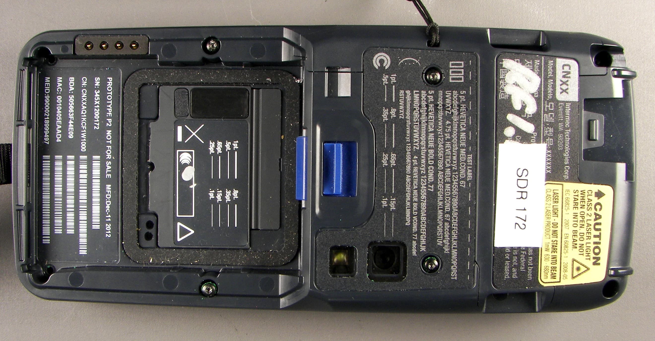
EHA-1015CP01SX1
Sep 08, 20131015CP01S
Equipment Class
PCE - PCS Licensed Transmitter held to ear
EHA-RC12ABGN
Aug 19, 2013WLAN board
Equipment Class
DSS - Part 15 Spread Spectrum Transmitter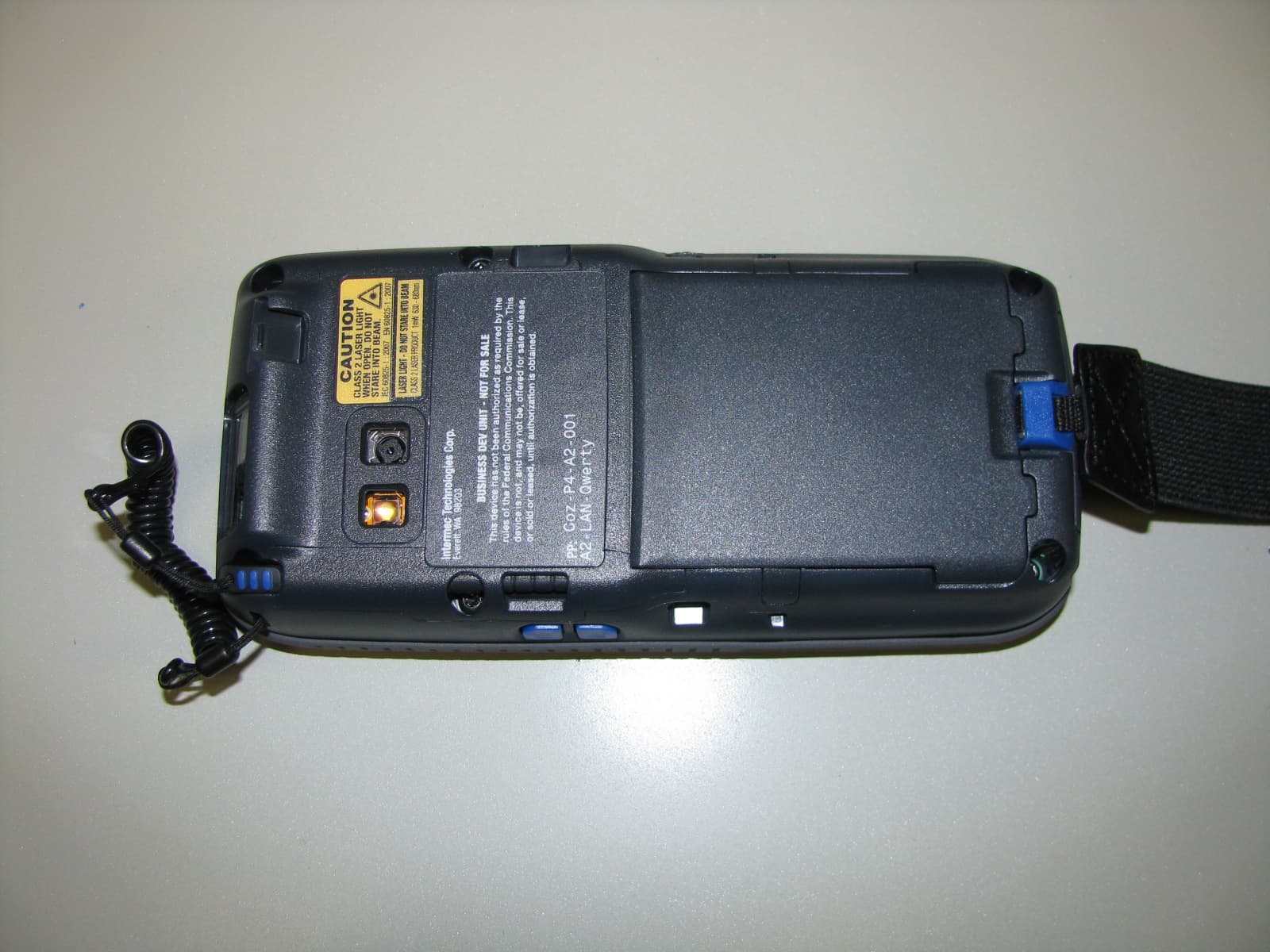
EHA-1000CP01F
Feb 19, 20131000CP01F9, 1000CP02F9, 1001CP01F9
Equipment Class
DTS - Digital Transmission System
EHA-INBT02
Dec 11, 2012BT Board
Equipment Class
DSS - Part 15 Spread Spectrum Transmitter