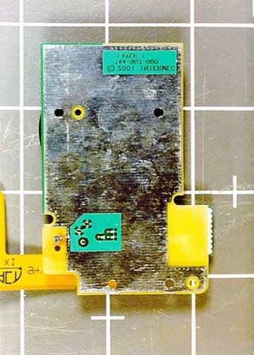
Click to zoom
Application Details
- Equipment Class
- DSS - Part 15 Spread Spectrum Transmitter
- Date of Grant
- Oct 22, 2001
- Application Purpose
- Original Equipment
- Date of Application
- Aug 16, 2001
- Frequency Range
- 2402.00000000 - 2480.00000000
- Country
- United States
Documents & Files
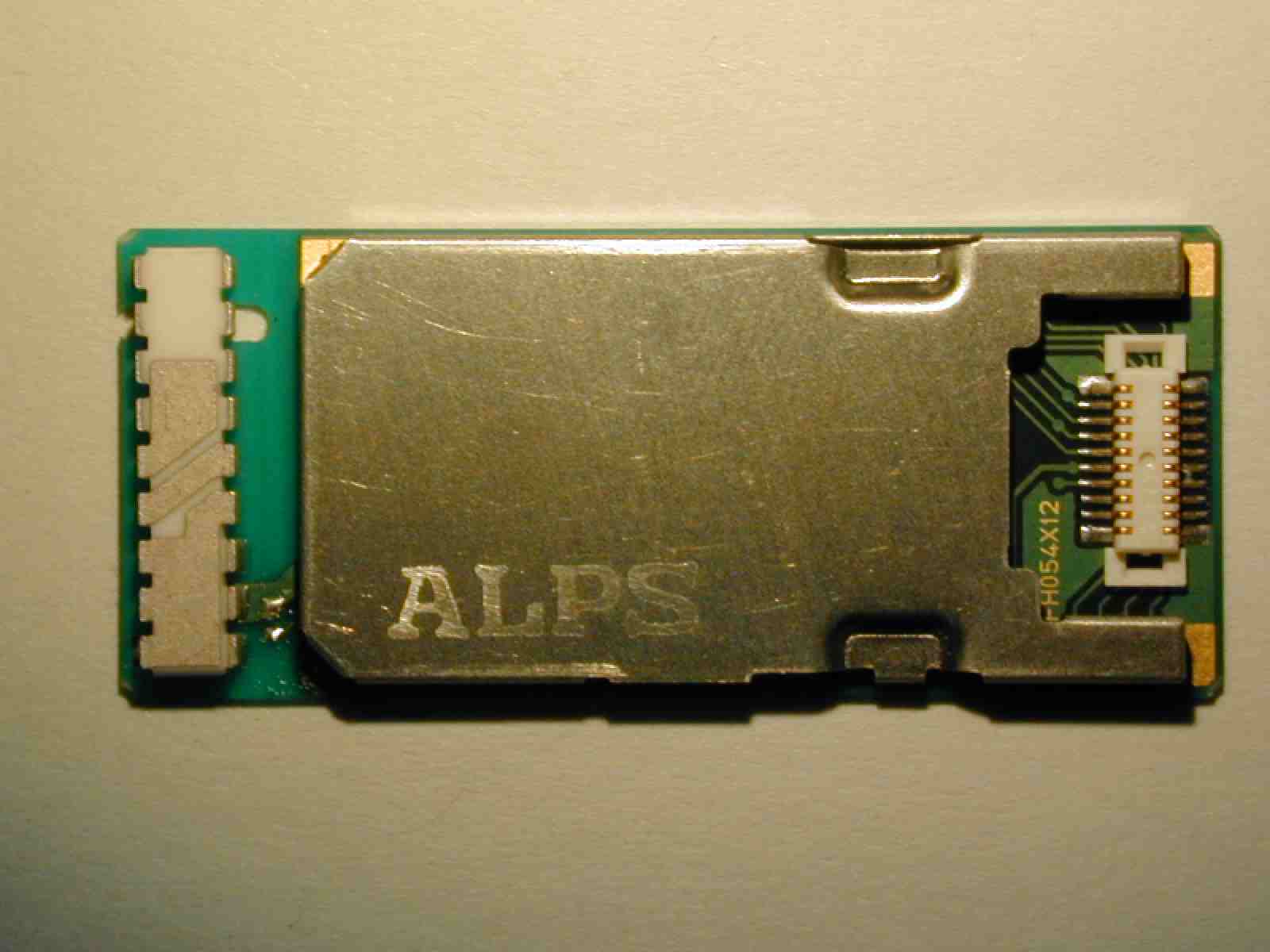
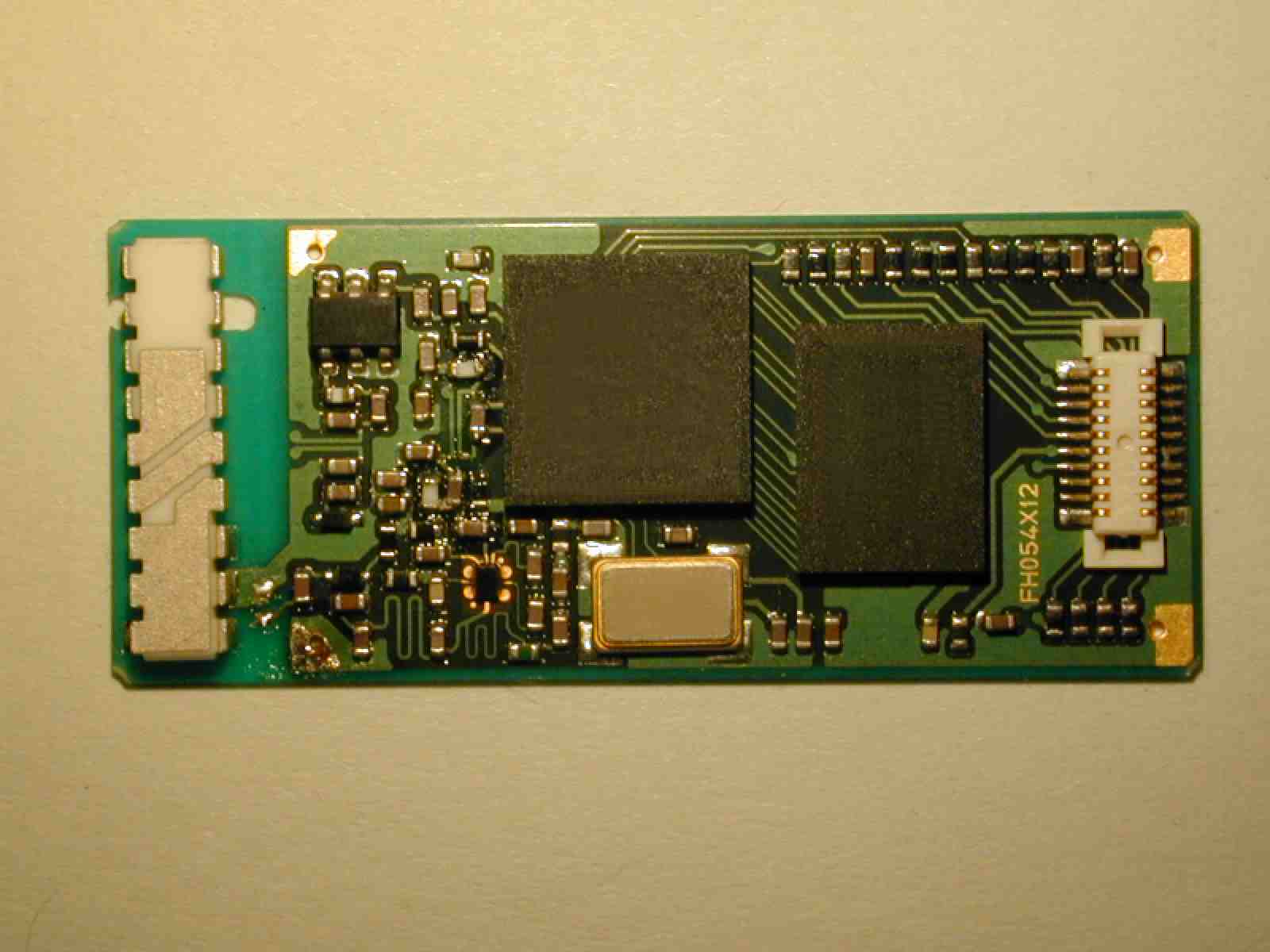
Document Text
Text extracted from the exhibit documents filed with the FCC. Open a document above to read the original.
Users Manual
Clarification about Compliance Insert The user manual information represents the ABTM3 radio within a typical final product. The Insert Sheets represents the data that will be included with all product that integrate the ABTM3 radio. OEM users will also be supplied with this information as well as information regarding requirements to verify the unintentional radiator emissions for final products that integrate the radio. The RF exposure report from Celltech shows no RF safety concerns. A statement on the user’s guide reflect the fact that the product was tested and the radio emissions comply to the RF exposure regulations.
Users Manual
578-100-056 Revision APage 1 of 2 *578-100-056* 578-100-056 Compliance Statement Insert Device Name: Pen Tablet ComputerModel Number: Model 700 (710 & 720 Configurations) The responsible party for the compliance of this device is:Intermec Technologies Corporation 6001 36 th Avenue West Everett, WA 98203 USA (425) 348-2600 CAUTION: See users guide instructions for handling, charging, and replacing batteries. Failure to follow those instructions can result in personal injury, fire, or battery explosion. This product conforms to the following approvals. The user(s) of this product are cautioned to use accessories and peripherals approved by Intermec Technologies Corporation. The use of accessories other than those recommended or changes to this product that are not approved by Intermec Technologies Corporation may void the compliance of this product and may result in the loss of the users authority to operate the equipment. This device complies with part 15 of the FCC and Industry Canada Rules. Operation is subject to the following two conditions: (1) this device may not cause harmful interference, and (2) this device must accept any interference received, including interference that may cause undesired operation. FCC Digital Emissions Compliance This equipment has been tested and found to comply with the limits for a Class B digital device, pursuant to Part 15 of the FCC Rules. These limits are designed to provide reasonable protection against harmful interference in a residential installation. This equipment generates, uses and can radiate radio frequency energy and, if not installed and used in accordance with the instructions, may cause harmful interference to radio communications. However, there is no guarantee that interference will not occur in a particular installation. If this equipment does cause harmful interference to radio or television reception, which can be determined by turning the equipment off and on, the user is encouraged to try to correct the interference by one or more of the following measures: • Reorient or relocate the radio or television receiving antenna. • Increase the separation between the computer equipment and receiver. • Connect the equipment into an outlet on a circuit different from that to which the radio or television receiver is connected. • Consult the dealer or an experienced radio television technician for help. Canadian Digital Apparatus Compliance This Class B digital apparatus meets all requirements of the Canadian Interference-Causing Equipment Regulations. Cet appareil numérique de la classe B respecte toutes les exigences du Règlement sur le matériel brouilleur du Canada. Radio Frequency Exposure Compliance for ABTM3 radio, FCC ID: EHAABTM3 CANADA: XXXXXXXX This equipment has been tested and found to comply with the limits for products using radio transmitters used by the general public. 578-100-056 Revision APage 2 of 2 *578-100-056* 578-100-056 DECLARATION OF CONFORMITY (According to ISO/IEC Guide 22 and EN 45014) PAGE ONE OF ONE THE PRODUCT HEREWITH COMPLIES WITH THE REQUIREMENTS OF : THE LOW-VOLTAGE DIRECTIVE 72/32/EEC. THE EMC DIRECTIVE 89/336/EEC. Manufacturer’s Name:European Representative: Intermec Technologies CorporationIntermec International Incorporated 6001 36 th Avenue WestSovereign House, Vastern Road Everett, WA 98203Reading, Berkshire RG1 8BT England Declares that the product listed below: Product Type:ITE/Residential, Commercial, and Light Industrial Product Name: Model 700 Model Number:Model 700Options: All Beginning Serial Number: AllDate Issued: February 26, 2001 Conforms to the following product specifications: Safety:IEC 950 / EN 60950 EMC:EN 55022 : 1994 + A1 : 1995 + A2 : 1997 / CISPR Publication 22 : 1993, Class B Limits and Methods EN 50024 : 1998 (CISPR 24) Information Technology Equipment – Immunity Characteristics – Limits and Methods of Measurement EN 61000-4-2 : 1995 – Electrostatic Discharge EN 61000-4-3 : 1995 – Radiated RF Field EN 61000-4-4 : 1995 – Electrical Fast Transients EN 61000-4-5 : 1995 – Voltage Surge EN 61000-4-6 : 1996 – Conducted RF Field EN 61000-4-11 : 1994 – Voltage Dips, Short Interruptions, and Variations EN61000-3-2 : 1995 + A1 : 1998 + A2 : 1998 + A14 : 2000 – Harmonic Current Emissions EN61000-3-3 : 1994 – Voltage Fluctuation and Flicker I, the undersigned, hereby declare that the equipment specified above conforms to the above Directive(s) and Standard(s). Company Official: Arvin DanielsonPosition: Vice President Signature: Signed Copy on File Date: February 26, 2001 European Contact: Scott Mercer, Intermec International Incorporated, Sovereign House, Vastern Road, Reading, Berkshire, RG1 8BT England; Phone INT+44 118 987 9400; Fax INT+44 118 987 9401
Attestation Statements
A Company August 16, 2001 Intermec Technologies Corporation Systems and Solutions 550 Second Street S.E. Cedar Rapids, IA 52401 T RANSM ITTER M ODULAR APPROVAL AT TEST AT ION Federal Communicatio ns Co mmission Authorization and Evaluation Division 7435 Oakland Mil a Road Columbia, Maryland 21046 Re: Application Modular Approval Certification for FCC ID: EHAABTM3 Gentlemen The following attestation addresses the eight requirements to support modular approval as required by the FCC Public Notice DA00-1407 “Part 15 Unlicensed Modular Transmitter Approval”. Transmitter modular approval, conditional require ments. 1) The ABTM3 radio module has its own shielding and is tested herein extended outside of an Intermec 700 terminal. The shield is added during manufacturing and is not easily removed. Instructions to end-users will warn of possible regulatory consequences for modifying the radio in any manner. 2) As a radio module designed specifically for data transfer, only data and power is presented to the radio. The radio circuitry buffers all modulation and control of the transmitter. Control of the transmitter is via data commands and software instructions contained within the module. The transmitter presented in the report is tested with the radio operated at the maximum power. Data commands may reduce the power transmitted but may not influence the modulation content. The operating band can be set to use 79 hopping channels within the 2400- 2483.5 MHz band or restrict operation to 23 hopping frequencies in the band limited to 2450-2483.5 MHz. This adjustment is made to the flash memory to configure DSP that operates the radio. The radio manufacturer or Intermec manufacturing and service are the only locations that may configure the flash memory. The flash memory software is under revision control by the regulatory staff. 3) This radio module does not contain an on-board voltage regulator. The transmitter is specified to operate across a voltage range of +3.3V +/- 0.2volt. Within the test report we show the operation of the transmitter across a voltage range of +2.9 to +3.5 volts. Testing shows the power output and operating frequency is maintained within the parameters defined in the regulations. The 3.3-volt source is a standard supply voltage in many “state of the art” mobile computers and portable printers. Products that do not have the industry standard 3.3 volts to operate the radio will have to incorporate a regulator to operate the radio within the +3.3v +/-0.2 volt range. All Intermec products have either a highly regulated supply sourced from the AC powerline or rechargeable batteries. For battery operated units there is a low battery cut-off to insure stable operation of the computer and memory. When low battery is detected all function ceases at a voltage that insures the processing and storage of data is not corrupted. The low battery detect also serves to maintain the operating voltage of the radio within the parameter specified above. Resellers for the radio will be instructed to maintain the voltage tolerances listed herein. 4) The radio uses an on-board antenna. The provisions to address a connector that meets the unique coupler requirements does not apply. 5) The radio is tested herein is on an extended flexible PC cable similar to those used within the Intermec 700. The radio is extended four inches (10-cm) beyond the host computer. The extender allows the radio to be placed horizontal and vertical for a complete evaluation of the radiated characteristics of the shielding on the radio. AC power to the Intermec 700 operated the unit during testing. AC line conducted emissions are presented utilizing the same 700 operating from the Intermec charger for the unit. Page 2FCC ID: EHAATBM3 Modular Approval Attestation, August 16, 2001 6) As a small module the radio not always accessible to the end user once the radio is integrated within a product. Products that restrict access to the radio will have an external label that is visible to users. The label will state “FCC ID: EHAABTM3”. Currently Intermec must install the radio during manufacturing. If and w hen the radio can be installed as a service retrofit, the service instructions will include labeling requirements for the exterior of the final product that addresses visibility of the FCC ID. The ABTM3 radio is not an option that the end user can install. The radio will be offered as an OEM radio to selected customer. Those Resellers will also be instructed to label the exterior of products where access to the PC card is restricted. 7) The radio module as manufactured is completely controlled by the onboard processor. There are no influences to the operation of the transmitter the end user can induce that will operate the radio outside of scope of the regulations. This radio complies to the operating conditions outlined in FCC Part 15.247 as a Frequency Hopping Spread Spectrum transmitter operating in the 2400-2483.5 MHz band. 8) The transmitter herein was tested with the antenna that is integrated on the radio module. Compliance to RF exposure requirements for this antenna is included within this application for approval. Appropriate warning statement will be placed with each end product user information based on the results of the RF exposure data filed with this application. OEM Resellers will be advised to include a similar statement to inform the users of any requirements for RF safety. Please contact me by telephone at (319) 846-2415 or by e-mail ([email protected]) if there are questions or additional information needed concerning this attestation. Yours tr ul y, Dave Fry, Regulatory Engineer II Intermec Technologies Corporation EMC Test Laboratory
Attestation Statements
The following section needs added to the report to support modular approval as required by the Public Notice attached for your reference. In the letter I will supply I will request “ Modular Approval”. df Transmitter modular approval, conditional requirements. 1) The ABTM3 radio module has its own shielding and is tested herein extended outside of an Intermec 700 terminal. The shield is added during manufacturing and is not easily removed. Instructions to end-users will warn of possible regulatory consequences for modifying the radio in any manner. 2) As a radio module designed specifically for data transfer, only data and power is presented to the radio, all modulation and control of the transmitter is contained within the module. 3) This radio module does not contain an on-board voltage regulator. The transmitter is specified to operate across a voltage range of +3.3V +/- 0.2volt. Within the test report we show the operation of the transmitter across a voltage range of +2.9 to +3.6 volts. Testing shows the power output and operating frequency is maintained within the parameters defined in the regulations. The 3.3-volt source is a standard supply voltage in many “state of the art” mobile computers and portable printers. Products that do not have the industry standard 3.3 volts to operate the radio will have to incorporate a regulator to operate the radio within the +3.3v +/-0.2 volt range. All Intermec products have either a highly regulated supply sourced from the AC powerline or rechargeable batteries. For battery operated units there is a low battery cut-off to insure stable operation of the computer and memory. When low battery is detected all function ceases at a voltage that insures the processing and storage of data is not corrupted. The low battery detect also serves to maintain the operating voltage of the radio within the parameter specified above. Resellers for the radio will be instructed to maintain the voltage tolerances listed herein. 4) The radio uses an on-board antenna. The provisions to address a connector that meets the unique coupler requirements does not apply. 5) The radio is tested here-in on an extended flexible PC cable similar to those used within the Intermec 700. The radio is extended four inches (10-cm) beyond the host computer. The extender allows the radio to be placed horizontal and vertical for a complete evaluation of the radiated characteristics of the shielding on the radio. AC power to the Intermec 700 operated the unit during testing. AC line conducted emissions are presented utilizing the same 700 operating from the Intermec charger for the unit. 6) As small module the radio not always accessible to the end user once the radio is integrated within a product. Products that restrict access to the radio will have an external label that is visible to users. The label will state “FCC ID: EHAABTM3”. Currently Intermec must install the radio during manufacturing. If and when the radio can be installed as a service retrofit the service instructions will include labeling requirements for the exterior of the final product that addresses visibility of the FCC ID. The ABTM3 radio is not an option that the end user can install. The radio will be offered as an OEM radio to selected customer. Those Resellers will also be instructed to label the exterior of products where access to the PC card is restricted. 7) The radio module as manufactured is completely controlled by the onboard processor. There are no influences to the operation of the transmitter the end user can induce that will operate the radio outside of scope of the regulations. The radio comes preprogrammed from ALPS. ALPS, Intermec service and manufacturing are the only persons with the equipment to alter the internal radio software that controls transmitter power, operating frequencies, hop sequences and duty cycle. All internal radio software that Intermec installs is placed under revision control within Intermec with restrictions under the supervision of Intermec Safety and Compliance manager. 8) The transmitter herein was tested with the antenna that is integrated on the radio module. Compliance to RF exposure requirements for this antenna is included within this application for approval. Appropriate warning statement will be placed with each end product user information based on the results of the RF exposure data filed with this application.
Attestation Statements
A Company August 16, 2001 Intermec Technologies Corporation Systems and Solutions 550 Second Street S.E. Cedar Rapids, IA 52401 T RANSM ITTER M ODULAR APPROVAL AT TEST AT ION Federal Communicatio ns Co mmission Authorization and Evaluation Division 7435 Oakland Mil a Road Columbia, Maryland 21046 Re: Application Modular Approval Certification for FCC ID: EHAABTM3 Gentlemen The following attestation addresses the eight requirements to support modular approval as required by the FCC Public Notice DA00-1407 “Part 15 Unlicensed Modular Transmitter Approval”. Transmitter modular approval, conditional require ments. 1) The ABTM3 radio module has its own shielding and is tested herein extended outside of an Intermec 700 terminal. The shield is added during manufacturing and is not easily removed. Instructions to end-users will warn of possible regulatory consequences for modifying the radio in any manner. 2) As a radio module designed specifically for data transfer, only data and power is presented to the radio. The radio circuitry buffers all modulation and control of the transmitter. Control of the transmitter is via data commands and software instructions contained within the module. The transmitter presented in the report is tested with the radio operated at the maximum power. Data commands may reduce the power transmitted but may not influence the modulation content. The operating band can be set to use 79 hopping channels within the 2400- 2483.5 MHz band or restrict operation to 23 hopping frequencies in the band limited to 2450-2483.5 MHz. This adjustment is made to the flash memory to configure DSP that operates the radio. The radio manufacturer or Intermec manufacturing and service are the only locations that may configure the flash memory. The flash memory software is under revision control by the regulatory staff. 3) This radio module does not contain an on-board voltage regulator. The transmitter is specified to operate across a voltage range of +3.3V +/- 0.2volt. Within the test report we show the operation of the transmitter across a voltage range of +2.9 to +3.5 volts. Testing shows the power output and operating frequency is maintained within the parameters defined in the regulations. The 3.3-volt source is a standard supply voltage in many “state of the art” mobile computers and portable printers. Products that do not have the industry standard 3.3 volts to operate the radio will have to incorporate a regulator to operate the radio within the +3.3v +/-0.2 volt range. All Intermec products have either a highly regulated supply sourced from the AC powerline or rechargeable batteries. For battery operated units there is a low battery cut-off to insure stable operation of the computer and memory. When low battery is detected all function ceases at a voltage that insures the processing and storage of data is not corrupted. The low battery detect also serves to maintain the operating voltage of the radio within the parameter specified above. Resellers for the radio will be instructed to maintain the voltage tolerances listed herein. 4) The radio uses an on-board antenna. The provisions to address a connector that meets the unique coupler requirements does not apply. 5) The radio is tested herein is on an extended flexible PC cable similar to those used within the Intermec 700. The radio is extended four inches (10-cm) beyond the host computer. The extender allows the radio to be placed horizontal and vertical for a complete evaluation of the radiated characteristics of the shielding on the radio. AC power to the Intermec 700 operated the unit during testing. AC line conducted emissions are presented utilizing the same 700 operating from the Intermec charger for the unit. Page 2FCC ID: EHAATBM3 Modular Approval Attestation, August 16, 2001 6) As a small module the radio not always accessible to the end user once the radio is integrated within a product. Products that restrict access to the radio will have an external label that is visible to users. The label will state “FCC ID: EHAABTM3”. Currently Intermec must install the radio during manufacturing. If and w hen the radio can be installed as a service retrofit, the service instructions will include labeling requirements for the exterior of the final product that addresses visibility of the FCC ID. The ABTM3 radio is not an option that the end user can install. The radio will be offered as an OEM radio to selected customer. Those Resellers will also be instructed to label the exterior of products where access to the PC card is restricted. 7) The radio module as manufactured is completely controlled by the onboard processor. There are no influences to the operation of the transmitter the end user can induce that will operate the radio outside of scope of the regulations. This radio complies to the operating conditions outlined in FCC Part 15.247 as a Frequency Hopping Spread Spectrum transmitter operating in the 2400-2483.5 MHz band. 8) The transmitter herein was tested with the antenna that is integrated on the radio module. Compliance to RF exposure requirements for this antenna is included within this application for approval. Appropriate warning statement will be placed with each end product user information based on the results of the RF exposure data filed with this application. OEM Resellers will be advised to include a similar statement to inform the users of any requirements for RF safety. Please contact me by telephone at (319) 846-2415 or by e-mail ([email protected]) if there are questions or additional information needed concerning this attestation. Yours tr ul y, Dave Fry, Regulatory Engineer II Intermec Technologies Corporation EMC Test Laboratory
Attestation Statements
A Company August 16, 2001 Intermec Technologies Corporation Systems and Solutions 550 Second Street S.E. Cedar Rapids, IA 52401 TRANSMITTER MODULAR APPROVAL ATTESTATION Federal Communications Commission Authorization and Evaluation Division 7435 Oakland Mil a Road Columbia, Maryland 21046 Re: Application Modular Approval Certification for FCC ID: EHAABTM3 Gentlemen The following attestation addresses the eight requirements to support modular approval as required by the FCC Public Notice DA00-1407 “Part 15 Unlicensed Modular Transmitter Approval”. Transmitter modular approval, conditional requirements. 1) The ABTM3 radio module has its own shielding and is tested herein extended outside of an Intermec 700 terminal. The shield is added during manufacturing and is not easily removed. Instructions to end-users will warn of possible regulatory consequences for modifying the radio in any manner. 2) As a radio module designed specifically for data transfer, only data and power is presented to the radio. The radio circuitry buffers all modulation and control of the transmitter. Control of the transmitter is via data commands and software instructions contained within the module. The transmitter presented in the report is tested with the radio operated at the maximum power. Data commands may reduce the power transmitted but may not influence the modulation content. The operating band can be set to use 79 hopping channels within the 2400- 2483.5 MHz band or restrict operation to 23 hopping frequencies in the band limited to 2450-2483.5 MHz. This adjustment is made to the flash memory to configure DSP that operates the radio. The radio manufacturer or Intermec manufacturing and service are the only locations that may configure the flash memory. The flash memory software is under revision control by the regulatory staff. 3) This radio module does not contain an on-board voltage regulator. The transmitter is specified to operate across a voltage range of +3.3V +/- 0.2volt. Within the test report we show the operation of the transmitter across a voltage range of +2.9 to +3.5 volts. Testing shows the power output and operating frequency is maintained within the parameters defined in the regulations. The 3.3-volt source is a standard supply voltage in many “state of the art” mobile computers and portable printers. Products that do not have the industry standard 3.3 volts to operate the radio will have to incorporate a regulator to operate the radio within the +3.3v +/-0.2 volt range. All Intermec products have either a highly regulated supply sourced from the AC powerline or rechargeable batteries. For battery operated units there is a low battery cut-off to insure stable operation of the computer and memory. When low battery is detected all function ceases at a voltage that insures the processing and storage of data is not corrupted. The low battery detect also serves to maintain the operating voltage of the radio within the parameter specified above. Resellers for the radio will be instructed to maintain the voltage tolerances listed herein. 4) The radio uses an on-board antenna. The provisions to address a connector that meets the unique coupler requirements does not apply. 5) The radio is tested herein is on an extended flexible PC cable similar to those used within the Intermec 700. The radio is extended four inches (10-cm) beyond the host computer. The extender allows the radio to be placed horizontal and vertical for a complete evaluation of the radiated characteristics of the shielding on the radio. AC power to the Intermec 700 operated the unit during testing. AC line conducted emissions are presented utilizing the same 700 operating from the Intermec charger for the unit. Page 2FCC ID: EHAATBM3 Modular Approval Attestation, August 16, 2001 6) As a small module the radio not always accessible to the end user once the radio is integrated within a product. Products that restrict access to the radio will have an external label that is visible to users. The label will state “FCC ID: EHAABTM3”. Currently Intermec must install the radio during manufacturing. If and when the radio can be installed as a service retrofit, the service instructions will include labeling requirements for the exterior of the final product that addresses visibility of the FCC ID. The ABTM3 radio is not an option that the end user can install. The radio will be offered as an OEM radio to selected customer. Those Resellers will also be instructed to label the exterior of products where access to the PC card is restricted. 7) The radio module as manufactured is completely controlled by the onboard processor. There are no influences to the operation of the transmitter the end user can induce that will operate the radio outside of scope of the regulations. This radio complies to the operating conditions outlined in FCC Part 15.247 as a Frequency Hopping Spread Spectrum transmitter operating in the 2400-2483.5 MHz band. 8) The transmitter herein was tested with the antenna that is integrated on the radio module. Compliance to RF exposure requirements for this antenna is included within this application for approval. Appropriate warning statement will be placed with each end product user information based on the results of the RF exposure data filed with this application. OEM Resellers will be advised to include a similar statement to inform the users of any requirements for RF safety. Please contact me by telephone at (319) 846-2415 or by e-mail ([email protected]) if there are questions or additional information needed concerning this attestation. Yours truly, Dave Fry, Regulatory Engineer II Intermec Technologies Corporation EMC Test Laboratory
Cover Letter(s)
A Company August 10, 2001 Intermec Technologies Corporation Systems and Solutions 550 Second Street S.E. Cedar Rapids, IA 52401 CONFIDENTIALITY REQUEST CONTAINED WITHIN Federal Communications Commission Authorization and Evaluation Division 7435 Oakland Mil a Road Columbia, Maryland 21046 Re: Application for Frequency Hopping Spread Spectrum Transceiver Certification Gentlemen Application: Intermec Technologies Corporation, 550 Second Street SE, Cedar Rapids, Iowa 52401-2029 herein submits: Application for Equipment Authorization (FCC Form 731 with integrated Fee Processing Form, Fee Codes EGC and EBC), application fee in the amount of $1130 and Exhibits; for Certification of a Frequency Hopping Spread Spectrum Transceiver FCC ID: EHAABTM3. Confidentiality: Pursuant to Section 0.459 of the Commission's rules (CFR 47), Intermec requests confidentiality for portions of the material contained in this application and that the identified material be withheld from public inspection following the grant of this authorization. This material contains trade secrets and confidential information that is not customarily release to the public and which is otherwise not generally available to the pubic. Confidentiality is requested for the following exhibits: • Theory of Operation • Schematics and associated documents • Block Diagram Description: This equipment is a FHSS radio module, which operates in the 2400-2483.5 MHz band. The radio operates as a one-milliwatt transceiver used to enable short-range wireless printing between Intermec hand-held computers and portable printers. Modular approval is requested to enable Intermec to integrate the wireless communication within several products. OEM sales of the module to selected customers are planned, integration instructions will outline the regulatory obligations regarding intentional and unintentional emissions approval. Modular approval greatly reduces the regulatory approval burden for multiple products with essentially the same characteristics. Contact Information: Please contact me by telephone at (319) 846-2415 or by e-mail ([email protected]) if there are questions or additional information needed concerning this filing. Yours truly, Dave Fry, Regulatory Engineer II Intermec Technologies Corporation EMC Test Laboratory
Cover Letter(s)
To: Joe Dichoso From: Joyce Walker, CKC Laboratories, Inc. Dave Fry, Intermec Technologies Date: Oct. 20, 2001 Re: FCC ID EHAABTM3 Reply to request for technical information. Applicant: Intermec Technologies Corporation Correspondence Reference Number: 20883 731 Confirmation Number: EA102062 1) The second label should state "This device contains TX FCC ID: EHAABTM3" Response: A corrected label for the exterior of end products that use the ABTM3 radio has been sent to the FCC EAS system. The corrected label and information to OEM integrators will specify using the statement “Contains TX FCC ID: EHAABTM3” 2) The SAR test shows that the tissue parameter for Body SAAR is not within 5%. Response: Celltech has sent a letter in response to …
Text truncated - open the document above for the full version.
Contact Information
Applicant
Brian Rudick(VP & GC, Honeywell Scanning & Mobility)
Technical Contact
Intermec Technologies CorporationDave Fry
[email protected]319-846-2415
5473A Clouds Rest · Cedar Rapids, California · United States
Non-Technical Contact
CKC Laboratories, Inc.Joyce Walker
[email protected]800-500-4362
Test Firm
CKC Laboratories, Inc.Steve Behm
Technical Specifications
| # | Rule Parts | Frequency Range | Power Output |
|---|---|---|---|
| 1 | 15C | 2.40 GHz - 2.48 GHz | 10.00 mW |
Other Applications from Intermec Technologies Corporation
EHA-1015CP01X1
Sep 29, 20131015CP01
Equipment Class
NII - Unlicensed National Information Infrastructure TX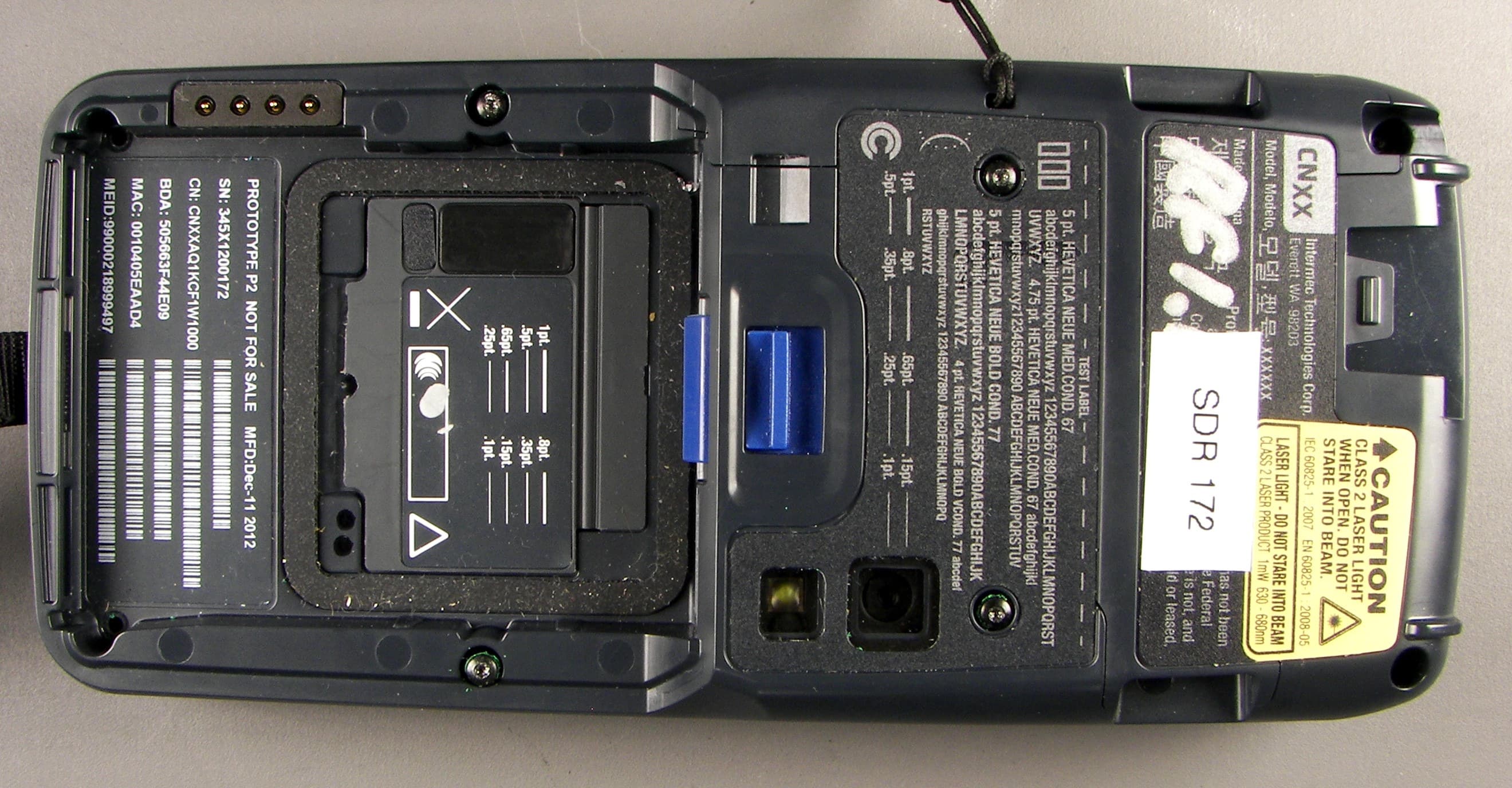
EHA-1015CP01SX1
Sep 08, 20131015CP01S
Equipment Class
PCE - PCS Licensed Transmitter held to ear
EHA-RC12ABGN
Aug 19, 2013WLAN board
Equipment Class
DSS - Part 15 Spread Spectrum Transmitter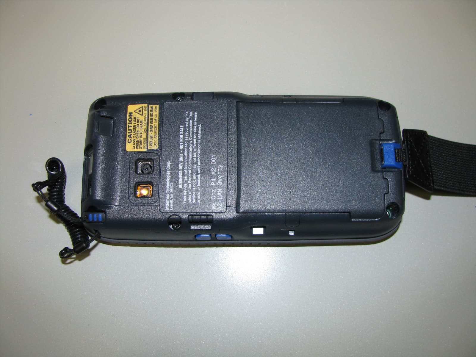
EHA-1000CP01F
Feb 19, 20131000CP01F9, 1000CP02F9, 1001CP01F9
Equipment Class
DTS - Digital Transmission System
EHA-INBT02
Dec 11, 2012BT Board
Equipment Class
DSS - Part 15 Spread Spectrum Transmitter