EHAITRM24501Intellitag RFID Radio
Intermec Technologies Corporation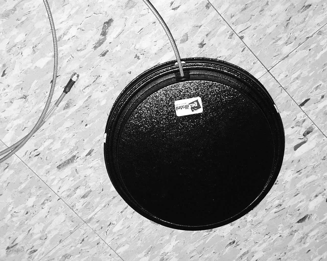
Click to zoom
Application Details
- Equipment Class
- DSS - Part 15 Spread Spectrum Transmitter
- Date of Grant
- Apr 22, 2002
- Application Purpose
- Original Equipment
- Date of Application
- Jan 03, 2002
- Equipment Note
- Intellitag RFID Radio
- Frequency Range
- 2402.00000000 - 2480.00000000
- Country
- United States
Documents & Files
Document Text
Text extracted from the exhibit documents filed with the FCC. Open a document above to read the original.
Users Manual
Intermec Technologies CorporationREPORT NO: 011214-1 EMC Test LaboratoryDATE: December 14, 2001 DOC. NO.: 577-501-006Page 1 of 2 ITRM24501 Radio Module, FCC 15.247, Canada RSS-210, RSS-102FCC ID: EHAITRM24501 APPENDIX L, Users Manual and DoC insert Technologies Corporation EMC Test Laboratory Cedar Rapids, IA MEASUREMENT/TECHNICAL REPORT Intermec Technologies Corporation Intellitag ITRM24501 Radio Module 2450 MHz Spread Spectrum Transmitter REPORT NO: 011214-1 DATE: December 14, 2001 APPENDIX L COMPLIANCE INSERT, USER INFORMATION FOR THE ITRM24501 RADIO MODULE 578-100-0xx Revision APage 1 of 1 *578-100-0xx* *578-100-0xx* Compliance Statement Insert Device Name: RF Identification Radio ModuleModel Number: ITRM24501 FCC ID: EHAITRM24501 The responsible party for the compliance of this device is:Intermec Technologies Corporation 6001 36 th Avenue West Everett, WA 98203 USA (425) 348-2600 This product conforms to the following approvals. The user(s) of this product are cautioned to use accessories and peripherals approved by Intermec Technologies Corporation. The use of accessories other than those recommended or changes to this product that are not approved by Intermec Technologies Corporation may void the compliance of this product and may result in the loss of the users authority to operate the equipment. This device complies with part 15 of the FCC and Industry Canada Rules. Operation is subject to the following two conditions: (1) This device may not cause harmful interference, and (2) this device must accept any interference received, including interference that may cause undesired operation. FCC Digital Emissions Compliance Note: This equipment has been tested and found to comply with the limits for a Class A digital device, pursuant to part 15 of the FCC Rules. These limits are designed to provide reasonable protection against harmful interference when the equipment is operated in a commercial environment. This equipment generates, uses, and can radiate radio frequency energy and , if not installed and used in accordance with the instruction manual, may cause harmful interference to radio communications. Operation of this equipment is a residential area is likely to cause harmful interference in which case the user will be required to correct the interference at his own expense. Canadian Digital Apparatus Compliance This Class A digital apparatus meets all requirements of the Canadian Interference-Causing Equipment Regulations. Cet appareil numérique de la classe A respecte toutes les exigences du Règlement sur le matériel brouilleur du Canada. WARNING: per the FCC and Canadian RF (radio frequency) exposure requirements, (1) Antennas must be supplied and installed as recommended by Intermec Technologies to ensure compliance to RF exposure requirements. The antennas approved for use are Intermec part numbers 805-605-001 and 805-576-101. Correct antenna mounting is fully described within the Intermec ITRM24501 Users Guide. (2) When installing and using Intermec approved remote antennas associated the RFID tag reader, a 20-cm (8-inch) passing distance must be maintained from any body part of the user or near by persons and the remote antenna. The antenna must not be touched during transmitter operation. (3) Cables attached to the remote antennas must have a minimum length as provided from Intermec to insure the proper losses to control RF exposure. (4) RF safety requirements mandate this device cannot be co-located with other transmitters. WARNING CANADA USERS: To prevent radio interference to the licensed service, this device is intended to be operated indoors and away from windows to provide maximum shielding. Equipment (or its transmit antenna) that is installed outdoors is subject to licensing. The end user is responsible to obtain the license.
Users Manual
ITRF24501 Reader Quick Start Guide PRELIMINARY EDITION 28--MAR--02 ITRF24501 Reader Quick Start Guide 2 Packing List WARNING: This is a Class A product. In a domestic environment this product may cause radio interference in which case the user may be required to take adequate measures. Check to ensure that you receive these items: Intermec R RR R 2450 Fixed Reader Model Number: ITRF24501 (part number country dependent) Product Warranty Card Compliance Statement RF ID 2450 MHz Dipoles on FR4 Sample Tags p/n ITTF2451001 ITRF24501 Reader Quick Start Guide 3 Host Communication Host communication comes through the 9-pin female D-sub connector. Both RS-232 and RS-422 standards are supported as ordered from the factory or service center. Table 1-1 RS-232 Connections Pin Number Definition 2Serial Data from the Fixed Reader to the host 3Serial Data to the Fixed Reader from the host 5Ground 7CTS (Clear to Send) to the Fixed Reader from the host 8RTS (Request to Send) from the Fixed Reader to the host Table 1-2 RS-422 Connections Pin Number Definition 1Serial Data Out + from the Fixed Reader to the host 4Serial Data Out -- from the Fixed Reader to the host 5Ground 6Serial Data In + to the Fixed Reader from the host 9Serial Data In -- to the Fixed Reader from the host The default baud rate is 115.2 kbps with 8 data bits, no parity and 1 stop bit. ITRF24501 Reader Quick Start Guide 4 Power Requirements Power comes in from 8 to 10 volts DC. The Fixed Reader uses less than 2 amps. Intermec supplies 9 volts DC at 2.4 amps from Intermec power supply, #351-066-001. User I/O A general purpose I/O (Input/Output) connector provides signal lines in and out of the reader allowing monitoring and/or con- trol of external devices or functions. The connector for this is a 13-pin female circular DIN. The mating male connector you need for mating with this is a CUI # SD-130, (one source is Digi-Key #CP-1013-ND). Table 1-3 I/O Pin-outs Pin Number Definition 1GPIOIN0 2GPIOIN1 3GPIOIN2 4GPIOIN3 5GPIOOUT0 6GPIOOUT1 7GPIOOUT2 8GPIOOUT3 9, 10, 11, 12, 13 GROUND though individual 10 ohm resistors Outputs and inputs have 12 volt transient suppression devices to ground at the connector. Output signals are driven by 2N3904 NPN transistors (low level) with a 100 kohm pull--up to +5 volts through a silicon diode, giving about a 4.3 volt high level. An output can be pulled high from an external source as high as 40 volts. This will however tend to pull the other out- puts higher (through two 100k resistors). The low level will be about 0.1 volt up to about 30 mA. The output low voltage will ITRF24501 Reader Quick Start Guide 5 climb higher as the sink current increases. There is no protec- tion on this. You need to ensure that their load won’t require thereadertosinkmorethan50mA. Input signals should be 0 to +1.5 volt for a low input and +3.5 to +5 volts for a high input. Each input has a 1.1 kohm resistor in series with clamping diodes, but only about 1PA is used until the input exceeds the 0 to +5 volt input range. There is also a weak (100 kohm) pull--up to +5 volt on each input. ITRF24501 Reader Quick Start Guide 6 Connecting and Getting Started WARNING: FCC regulations limit exposure to radiofrequency (RF) radiation. To comply with these regulations, operators of this device must maintain a distance of at least 20 cm. (8 inches) from the cover on the antenna assembly (The cover on the antenna is the dome shaped surface). While the device is on, the operator’s body and parts of the body such as eyes, hands, or head, must be 20 cm. (8 inches) or farther from the cover of the antenna assembly. FCC regulations also require that the antenna assembly of this device be installed in accordance with the installation procedures to allow the operator to comply with the limit. ITRF24501 Reader Quick Start Guide 7 Antenna Installation Ensure that you read the above warning before installing the antennas and using your Reader product. Back viewFront view Reader to antenna cable Mounting bracket 1. Review the locations where the Reader products need in- tegrated. Ensure that you have careful considered the safe distances for product placement for workers and any other personnel that may get in the RF path. 2. Place the radio and antennas with cabling are easily ac- cessible for installation and troubleshooting. 3. Use the mounting bracket to attach the antenna to a fixed surface. 4. Attach the antenna to one of the four antenna ports on the back of the Reader. ITRF24501 Reader Quick Start Guide 8 The following illustration is an example of a typical Reader installation. EXAMPLE:Two Product Line Conveyers, showing two antennas on each line. Two antennas in a crossing pattern provide angular diversity to improve read capability when tag orientation is unknown. The frames for these stations are PVC tubing with RF reflec- tive Mylar liner X2. Ensure that an eight inch (20 cm) distance from the antenna assembly is maintained to limit people’s ex- posure to radiofrequency (RF) radiation. WARNING: While the device is on, the operator’s body and parts of the body such as eyes, hands, or head, must be 20 cm. (8 inches) or farther from the cover of the antenna assembly. Conveyer Belt #1 Conveyer Belt #2 33” Max. distance to tag A singular antenna in a portal may be sufficient in applications where there is a known tag orientation ITRF24501 Reader Quick Start Guide 9 Connecting the Antenna to the Reader 1. Connect the antenna cable to a port. 2. Connect an SMA reverse--sex SMA terminator (Intermec p/n 345-004-001) to any port that does not have an anten- na attached. " NOTE: Each port must have either an antenna or a termina- tor connected. 1 2 3 4 Antenna ports Back panel Antenna cable SMA terminator 3. Connect the Reader to a power source using power supply p/n 351-066-001 and country dependent AC power cord. 4. Turn on your reader. Power supply Power cord ITRF24501 Reader Quick Start Guide 10 5. Review the front panel LEDs to become familiar with…
Text truncated - open the document above for the full version.
Attestation Statements
A Company January 8, 2002 Intermec Technologies Corporation Systems and Solutions 550 Second Street S.E. Cedar Rapids, IA 52401 Attestation for final printed circuit board changes. Federal Communications Commission Authorization and Evaluation Division 7435 Oakland Mills Road Columbia, Maryland 21046 Re: Application of Modular Approval for Frequency Hopping Spread Spectrum (FHSS) Transceiver Certification FCC ID: EHAITRM24501 Gentlemen The radio tested for this application is a prototype with minor board modifications needed to correct problems. The schematics and parts placement shows the same board with modifications incorporated in the printed circuit board. The cleaned up board version will be used for production and sales. Intermec will perform a complete test of the production PCB and will file a Class II Permissive Change request if the margins for compliance are less than reported with this application. If the margins of compliance on the production board are better than reported in this application, a Class I Permissive Change report will be generated and placed on file at Intermec. Please contact me by telephone at (319) 846-2415 or by e-mail ([email protected]) if there are questions or additional information needed concerning this attestation. Yours truly, Dave Fry, Regulatory Engineer II Intermec Technologies Corporation EMC Test Laboratory
Attestation Statements
To:Joe Dichoso [email protected] FCC Application Processing Branch From:Dave Fry Sent: Thursday, March 28, 2002 Re:FCC ID EHAITRM24501 Applicant:Intermec Technologies Corporation Correspondence Reference Number:22244 731 Confirmation Number:EA265718 Note: The reply to your inquiry is in bold Italics print. 1) Verify that in no case do the antennas transmit simultaneously. Only one antenna path can be selected at a time on the Penn 2450 MHz interrogator. Each PIN diode pole pair, CR6 & CR11, CR7 & CR8, and CR9 & CR10, is driven by opposite logic outputs of inverter U5. This forces one pole off when the alternate pole is turned on. John Jorgenson 2) FYI, the exact details of the "minor modifications" need to be taken into account to determine whether another filing is required. It is not based soley on radiated emissions. Any modifications made will be limited to printed circuit layout that removes the cut and jumpers required for the version of board submitted. The final board for production is represented with the testing for this application. The production board will be fully evaluated for all sections of the FCC rules, addressing both conducted and radiated characteristics. In the event the characteristics for the final board are worse than those reported in this application, a FCC Class 2 Permissive Change report will be submitted for FCC review and approval prior to marketing and shipping. SAR QUESTIONS. (TH) RT: 1. Need complete users manual to evaluate installation and normal use conditions. An Intermec Quick Start Guide for the final reader offering is downloaded to the FCC EAS system.
Attestation Statements
To:Joe Dichoso [email protected] FCC Application Processing Branch From:Dave Fry Date:Apr 12, 2002 Re:FCC ID EHAITRM24501 Applicant:Intermec Technologies Corporation Correspondence Reference Number:22574 731 Confirmation Number:EA265718 My reply is in bold italic. 1) Please provide an RF safety label that will be placed on the antennas and that indicates the 20 cm separation. A diagram of the warning label is shown below. The text for the word “WARNING” will be a minimum of 24-point type in red letters. Use of the yellow radiation hazard-warning symbol as defined in ANSI C95.2 will be evaluated and included if it can be implemented cost effectively. At a minimum the red word warning and included text will be as shown. The label placement will be on the front of the antenna readily visible to persons nearby. 2) Verify that the tags are passive(e.g. do not contain batteries) or indicate the FCC identifier for them. All tags for the Intermec Intellitag™ systems are passive. When Intermec requires the use of battery powered tags, the proper regulatory approvals will be pursued. WARNING: Government limits to radio frequency exposure may be exceeded at distances less than 20 cm (8 inches) from this antenna.
Cover Letter(s)
A Company January 4, 2002 Intermec Technologies Corporation Systems and Solutions 550 Second Street S.E. Cedar Rapids, IA 52401 CONFIDENTIALITY REQUEST CONTAINED WITHIN Federal Communications Commission Authorization and Evaluation Division 7435 Oakland Mills Road Columbia, Maryland 21046 Re: Application of Modular Approval for Frequency Hopping Spread Spectrum (FHSS) Transceiver Certification FCC ID: EHAITRM24501 Gentlemen Application: Intermec Technologies Corporation, 550 Second Street SE, Cedar Rapids, Iowa 52401-2029 herein submits: Application for Equipment Authorization (FCC Form 731 with integrated Fee Processing Form, Fee Codes EGC and EBC), application fee in the amount of $1130 and Exhibits; for Certification of a Frequency Hopping Spread Spectrum Transceiver FCC ID: EHAITRM24501. Intermec is also the manufacturer of this equipment. Confidentiality: Pursuant to Section 0.459 of the Commission's rules (CFR 47), Intermec requests confidentiality for portions of the material contained in this application and that the identified material be withheld from public inspection following the grant of this authorization. This material contains Intermec trade secrets and confidential information that Intermec does not customarily release to the public and which is otherwise not generally available to the pubic. Confidentiality is requested for the following exhibits: • Appendix I Theory of Operation • Appendix J Block Diagram • Appendix K Schematics, Parts List and Placement Description: This equipment is a FHSS radio module, which operates in the 2400-2483.5 MHz band. It can interrogate and write to RFID tags operating in the same frequency band. Modular approval is requested since the radio design allows use in multiple hosts of various configurations. Statements addressing conditions for modular approval are contained within the main body of the test report. Contact Information: Please contact me by telephone at (319) 846-2415 or by e-mail ([email protected]) if there are questions or additional information needed concerning this filing. Yours truly, Dave Fry, Regulatory Engineer II Intermec Technologies Corporation EMC Test Laboratory
External Photos
Intermec Technologies CorporationREPORT NO: 011214-1 EMC Test LaboratoryDATE: December 14, 2001 DOC. NO.: 577-501-006Page 1 of 6 ITRM24501 Radio Module, FCC 15.247, Canada RSS-210, RSS-102FCC ID: EHAITRM24501 APPENDIX B, Radio and Antenna Photos Technologies Corporation EMC Test Laboratory Cedar Rapids, IA MEASUREMENT/TECHNICAL REPORT Intermec Technologies Corporation Intellitag ITRM24501 Radio Module 2450 MHz Spread Spectrum Transmitter REPORT NO: 011214-1 DATE: December 14, 2001 APPENDIX C THE FOLLOWING PAGES INCLUDE; Page 2Module Front Module Back Page 3Module Antenna Connector End Module D-Sub Connector End Page 4Module Side View Page 5Front View, Intermec 5.9 dBi, 9 Inch Round Patch Antenna Back View, Intermec 5.9 dBi, 9 Inch Round Patch Antenna Page 6Front View, Huber Suhner 3.5 dBi Patch Antenna Back View, Huber Suhner 3.5 dBi Patch Antenna Intermec Technologies CorporationREPORT NO: 011214-1 EMC Test LaboratoryDATE: December 14, 2001 DOC. NO.: 577-501-006Page 2 of 6 ITRM24501 Radio Module, FCC 15.247, Canada RSS-210, RSS-102FCC ID: EHAITRM24501 APPENDIX B, Radio and Antenna Photos Intermec Technologies CorporationREPORT NO: 011214-1 EMC Test LaboratoryDATE: December 14, 2001 DOC. NO.: 577-501-006Page 3 of 6 ITRM24501 Radio Module, FCC 15.247, Canada RSS-210, RSS-102FCC ID: EHAITRM24501 APPENDIX B, Radio and Antenna Photos Intermec Technologies CorporationREPORT NO: 011214-1 EMC Test LaboratoryDATE: December 14, 2001 DOC. NO.: 577-501-006Page 4 of 6 ITRM24501 Radio Module, FCC 15.247, Canada RSS-210, RSS-102FCC ID: EHAITRM24501 APPENDIX B, Radio and Antenna Photos Intermec Technologies CorporationREPORT NO: 011214-1 EMC Test LaboratoryDATE: December 14, 2001 DOC. NO.: 577-501-006Page 5 of 6 ITRM24501 Radio Module, FCC 15.247, Canada RSS-210, RSS-102FCC ID: EHAITRM24501 APPENDIX B, Radio and Antenna Photos Intermec Technologies CorporationREPORT NO: 011214-1 EMC Test LaboratoryDATE: December 14, 2001 DOC. NO.: 577-501-006Page 6 of 6 ITRM24501 Radio Module, FCC 15.247, Canada RSS-210, RSS-102FCC ID: EHAITRM24501 APPENDIX B, Radio and Antenna Photos
ID Label/Location Info
Intermec Technologies CorporationREPORT NO: 011214-1 EMC Test LaboratoryDATE: December 14, 2001 DOC. NO.: 577-501-006Page 1 of 4 ITRM24501 Radio Module, FCC 15.247, Canada RSS-210, RSS-102FCC ID: EHAITRM24501 APPENDIX A, Label and Label Placement Technologies Corporation EMC Test Laboratory Cedar Rapids, IA MEASUREMENT/TECHNICAL REPORT Intermec Technologies Corporation Intellitag ITRM24501 Radio Module 2450 MHz Spread Spectrum Transmitter REPORT NO: 011214-1 DATE: December 14, 2001 APPENDIX A LABEL AND PLACEMENT DIAGRAMS Intermec Technologies CorporationREPORT NO: 010312-1 EMC Test LaboratoryDATE: March 12, 2001 DOC. NO.: 577-500-979Page 2 of 4 2450 PC Card Radio Module, FCC 15.247, Canada RSS-210, RSS-102FCC ID: EHARFID2450PCC-5 APPENDIX A, Conducted and Radiated Measurement Photos PRODUCT LABELING See the following diagrams showing the labels for the radio module as well as placements. Module label Intermec Technologies CorporationREPORT NO: 010312-1 EMC Test LaboratoryDATE: March 12, 2001 DOC. NO.: 577-500-979Page 3 of 4 2450 PC Card Radio Module, FCC 15.247, Canada RSS-210, RSS-102FCC ID: EHARFID2450PCC-5 APPENDIX A, Conducted and Radiated Measurement Photos Placement on the radio module Intermec Technologies CorporationREPORT NO: 010312-1 EMC Test LaboratoryDATE: March 12, 2001 DOC. NO.: 577-500-979Page 4 of 4 2450 PC Card Radio Module, FCC 15.247, Canada RSS-210, RSS-102FCC ID: EHARFID2450PCC-5 APPENDIX A, Conducted and Radiated Measurement Photos Exterior label for products covering or not allowing visibility to module label.
Internal Photos
Intermec Technologies CorporationREPORT NO: 011214-1 EMC Test LaboratoryDATE: December 14, 2001 DOC. NO.: 577-501-006Page 1 of 4 ITRM24501 Radio Module, FCC 15.247, Canada RSS-210, RSS-102FCC ID: EHAITRM24501 APPENDIX B, Radio and Antenna Photos Technologies Corporation EMC Test Laboratory Cedar Rapids, IA MEASUREMENT/TECHNICAL REPORT Intermec Technologies Corporation Intellitag ITRM24501 Radio Module 2450 MHz Spread Spectrum Transmitter REPORT NO: 011214-1 DATE: December 14, 2001 APPENDIX D THE FOLLOWING PAGES INCLUDE; Page 2PCB Front PCB Back With Codec Board Page 3PBC Back Without Codec Board Page 4Codec Board Front Codec Board Back Intermec Technologies CorporationREPORT NO: 011214-1 EMC Test LaboratoryDATE: December 14, 2001 DOC. NO.: 577-501-006Page 2 of 4 ITRM24501 Radio Module, FCC 15.247, Canada RSS-210, RSS-102FCC ID: EHAITRM24501 APPENDIX B, Radio and Antenna Photos Intermec Technologies CorporationREPORT NO: 011214-1 EMC Test LaboratoryDATE: December 14, 2001 DOC. NO.: 577-501-006Page 3 of 4 ITRM24501 Radio Module, FCC 15.247, Canada RSS-210, RSS-102FCC ID: EHAITRM24501 APPENDIX B, Radio and Antenna Photos Intermec Technologies CorporationREPORT NO: 011214-1 EMC Test LaboratoryDATE: December 14, 2001 DOC. NO.: 577-501-006Page 4 of 4 ITRM24501 Radio Module, FCC 15.247, Canada RSS-210, RSS-102FCC ID: EHAITRM24501 APPENDIX B, Radio and Antenna Photos
RF Exposure Info
Intermec Technologies CorporationREPORT NO: 011214-1 EMC Test LaboratoryDATE: December 14, 2001 DOC. NO.: 577-501-006Page 1 of 3 ITRM24501 Radio Module, FCC 15.247, Canada RSS-210, RSS-102FCC ID: EHAITRM24501 APPENDIX M, MPE RF Exposure Calculations Technologies Corporation EMC Test Laboratory Cedar Rapids, IA MEASUREMENT/TECHNICAL REPORT Intermec Technologies Corporation Intellitag ITRM24501 Radio Module 2450 MHz Spread Spectrum Transmitter REPORT NO: 011214-1 DATE: December 14, 2001 APPENDIX M MAXIMUM PERMISSIVE EXPOSURE Technologies Corporation David L. Fry EMC Test Laboratory Regulatory Engineer Cedar Rapids, IA Date: Jan. 4, 2002 MPE CalculatordBi5.90 dBd + 2.17 = dBidBi to dBd2.17 TX Frequency (MHz)2450Watts1Antenna Gain dBd3.73 Cable Losses dB0dBm30.000000 radiated (ERP) dBm33.730 radiated (EIRP) dBm35.900 Ocupational Limit 5.0mW/cm meterscm General Public Limit0.1224489812.245 1.0mW/cm d = cmEIRP=mW occ.limitpublic limit f/1500f/300 51 MPE uses EIRP for calculations. EIRP is based on TX power added to the antenna gain in dBi. dBi = dB gain compared to an isotropic radiator EIRPDistanceDistanceDistance (watts)(cm)(Meters)(inches)mW/cm 3890.451100.01.00039.370.03096 3890.45175.00.75029.530.05504 3890.45150.00.50019.690.12384 3890.45140.00.40015.750.19350 3890.45130.00.30011.810.34399 3890.45120.00.2007.870.77398 3890.45119.50.1957.680.81418 3890.45119.00.1907.480.85760 3890.45118.50.1857.280.90458 3890.45118.00.1807.090.95553 3890.45117.50.1756.891.01091 3890.45117.00.1706.691.07125 3890.45116.50.1656.501.13716 3890.45116.00.1606.301.20934 3890.45115.50.1556.101.28863 3890.45115.00.1505.911.37597 3890.45114.50.1455.711.47250 3890.45114.00.1405.511.57955 3890.45113.50.1355.311.69872 3890.45113.00.1305.121.83191 3890.45112.50.1254.921.98139 wavelength TX Frequency (MHz) 1,500-10,000 Freq. MHz 300-1,500 FCC radiofrequency radiation exposure limits 1.1310 MAXIMUM PERMISSIVE EXPOSURE, MPE CALCULATOR ITRM24501 radio with 5.9 dBi antenna Calculated EIRP (mW)3890.451450 Calculated ERP (mW)2360.478233 Intermec MN/PN IT245005 / 805-605-001 EIRP = mw/cm 2 2 4 II d 2 2 2 5.9 dBi Intermec MPE EIRP 2450 MHz calculator.xlsPage 1 of 1 Technologies Corporation David L. Fry EMC Test Laboratory Regulatory Engineer Cedar Rapids, IA Date: Jan. 4, 2002 MPE CalculatordBi3.10 dBd + 2.17 = dBidBi to dBd2.17 TX Frequency (MHz)2450Watts1Antenna Gain dBd0.93 Cable Losses dB0dBm30.000000 radiated (ERP) dBm30.930 radiated (EIRP) dBm33.100 Ocupational Limit 5.0mW/cm meterscm General Public Limit0.1224489812.245 1.0mW/cm d = cmEIRP=mW occ.limitpublic limit f/1500f/300 51 MPE uses EIRP for calculations. EIRP is based on TX power added to the antenna gain in dBi. dBi = dB gain compared to an isotropic radiator EIRPDistanceDistanceDistance (watts)(cm)(Meters)(inches)mW/cm 2041.738100.01.00039.370.01625 2041.73875.00.75029.530.02888 2041.73850.00.50019.690.06499 2041.73840.00.40015.750.10155 2041.73830.00.30011.810.18053 2041.73820.00.2007.870.40619 2041.73819.50.1957.680.42729 2041.73819.00.1907.480.45007 2041.73818.50.1857.280.47473 2041.73818.00.1807.090.50147 2041.73817.50.1756.890.53053 2041.73817.00.1706.690.56220 2041.73816.50.1656.500.59679 2041.73816.00.1606.300.63467 2041.73815.50.1556.100.67628 2041.73815.00.1505.910.72212 2041.73814.50.1455.710.77278 2041.73814.00.1405.510.82896 2041.73813.50.1355.310.89150 2041.73813.00.1305.120.96140 2041.73812.50.1254.921.03985 MAXIMUM PERMISSIVE EXPOSURE, MPE CALCULATOR ITRM24501 radio with 3.1 dBi antenna Calculated EIRP (mW)2041.737945 Calculated ERP (mW)1238.796587 Intermec PN 805-576-101 (Huber Suhner) wavelength TX Frequency (MHz) 1,500-10,000 Freq. MHz 300-1,500 FCC radiofrequency radiation exposure limits 1.1310 EIRP = mw/cm 2 2 4 II d 2 2 2 3.1 dBi HS MPE EIRP 2450 MHz calculator.xlsPage 1 of 1
Test Report
Intermec Technologies CorporationREPORT NO: 011214-1 EMC Test LaboratoryDATE: December 14, 2001 DOC. NO.: 577-501-006Page 1 of 6 ITRM24501 Radio Module, FCC 15.247, Canada RSS-210, RSS-102FCC ID: EHAITRM24501 APPENDIX E, Transmitter Conducted Plots, 20 dB BW, Number of Channels, Channel Occupancy, TX Power Technologies Corporation EMC Test Laboratory Cedar Rapids, IA MEASUREMENT/TECHNICAL REPORT Intermec Technologies Corporation Intellitag ITRM24501 Radio Module 2450 MHz Spread Spectrum Transmitter REPORT NO: 011214-1 DATE: December 14, 2001 APPENDIX E THE FOLLOWING PLOTS ARE INCLUDED; 20 dB Band Width TX Channel 02 Channel 41 Channel 80 Channel Separation Channel Dwell Time 4 second sweep 100 milli-second sweep Number of Hopping Channels Transmitter Power TX Channel 02 Channel 41 Channel 80 Intermec Technologies CorporationREPORT NO: 010312-1 EMC Test LaboratoryDATE: March 12, 2001 DOC. NO.: 577-500-979Page 2 of 6 2450 PC Card Radio Module, FCC 15.247, Canada RSS-210, RSS-102FCC ID: EHARFID2450PCC-5 APPENDIX E Transmitter Conducted Plots, 20 dB BW, Number of Channels, Channel Occupancy Intermec Technologies CorporationREPORT NO: 010312-1 EMC Test LaboratoryDATE: March 12, 2001 DOC. NO.: 577-500-979Page 3 of 6 2450 PC Card Radio Module, FCC 15.247, Canada RSS-210, RSS-102FCC ID: EHARFID2450PCC-5 APPENDIX E Transmitter Conducted Plots, 20 dB BW, Number of Channels, Channel Occupancy Intermec Technologies CorporationREPORT NO: 010312-1 EMC Test LaboratoryDATE: March 12, 2001 DOC. NO.: 577-500-979Page 4 of 6 2450 PC Card Radio Module, FCC 15.247, Canada RSS-210, RSS-102FCC ID: EHARFID2450PCC-5 APPENDIX E Transmitter Conducted Plots, 20 dB BW, Number of Channels, Channel Occupancy Intermec Technologies CorporationREPORT NO: 010312-1 EMC Test LaboratoryDATE: March 12, 2001 DOC. NO.: 577-500-979Page 5 of 6 2450 PC Card Radio Module, FCC 15.247, Canada RSS-210, RSS-102FCC ID: EHARFID2450PCC-5 APPENDIX E Transmitter Conducted Plots, 20 dB BW, Number of Channels, Channel Occupancy Intermec Technologies CorporationREPORT NO: 010312-1 EMC Test LaboratoryDATE: March 12, 2001 DOC. NO.: 577-500-979Page 6 of 6 2450 PC Card Radio Module, FCC 15.247, Canada RSS-210, RSS-102FCC ID: EHARFID2450PCC-5 APPENDIX E Transmitter Conducted Plots, 20 dB BW, Number of Channels, Channel Occupancy
Test Report
Intermec Technologies CorporationREPORT NO: 011214-1 EMC Test LaboratoryDATE: December 14, 2001 DOC. NO.: 577-501-006Page 1 of 4 ITRM24501 Radio Module, FCC 15.247, Canada RSS-210, RSS-102FCC ID: EHAITRM24501 APPENDIX F, Transmitter Conducted Plots, Out of Band Emissions Technologies Corporation EMC Test Laboratory Cedar Rapids, IA MEASUREMENT/TECHNICAL REPORT Intermec Technologies Corporation Intellitag ITRM24501 Radio Module 2450 MHz Spread Spectrum Transmitter REPORT NO: 011214-1 DATE: December 14, 2001 APPENDIX F THE FOLLOWING PLOTS ARE INCLUDED; In-Band Emissions 139.166667 MHz Span Spurious 0-5 GHz Spurious 5-10 GHz Spurious 10-25 GHz Low Band Edge High Band Edge Intermec Technologies CorporationREPORT NO: 010312-1 EMC Test LaboratoryDATE: March 12, 2001 DOC. NO.: 577-500-979Page 2 of 4 2450 PC Card Radio Module, FCC 15.247, Canada RSS-210, RSS-102FCC ID: EHARFID2450PCC-5 APPENDIX D, Transmitter Conducted Plots, Out of Band Emissions Intermec Technologies CorporationREPORT NO: 010312-1 EMC Test LaboratoryDATE: March 12, 2001 DOC. NO.: 577-500-979Page 3 of 4 2450 PC Card Radio Module, FCC 15.247, Canada RSS-210, RSS-102FCC ID: EHARFID2450PCC-5 APPENDIX D, Transmitter Conducted Plots, Out of Band Emissions Intermec Technologies CorporationREPORT NO: 010312-1 EMC Test LaboratoryDATE: March 12, 2001 DOC. NO.: 577-500-979Page 4 of 4 2450 PC Card Radio Module, FCC 15.247, Canada RSS-210, RSS-102FCC ID: EHARFID2450PCC-5 APPENDIX D, Transmitter Conducted Plots, Out of Band Emissions
Test Report
Intermec Technologies CorporationREPORT NO: 011214-1 EMC Test LaboratoryDATE: December 14, 2001 DOC. NO.: 577-501-006Page 1 of 27 ITRM24501 Radio Module, FCC 15.247, Canada RSS-210, RSS-102FCC ID: EHAITRM24501 APPENDIX G, TX radiated emissions data, worst case configurations Technologies Corporation EMC Test Laboratory Cedar Rapids, IA MEASUREMENT/TECHNICAL REPORT Intermec Technologies Corporation Intellitag ITRM24501 Radio Module 2450 MHz Spread Spectrum Transmitter REPORT NO: 011214-1 DATE: December 14, 2001 APPENDIX G THE FOLLOWING PAGES INCLUDE; Page 2-3, Configurations tested to determine worst case system(s). Configurations Average and peak radiated spurious emissions. No emissions found below the transmitter fundamental operating frequency. Pages 4-9 Radio as a module positioned horizontally. 2 antennas connected to ports 1 and 4, port 4 active. Pages 10-15 Radio as a module positioned vertically. 2 antennas connected to ports 1 and 4, port 4 active. Pages 16-21 Radio as a module positioned horizontally. 4 antennas connected, ports 1 and 4 to antennas on site, ports 2 and 3 to remote antennas, port 4 active. Configuration 1. Page…
Text truncated - open the document above for the full version.
Contact Information
Applicant
Brian Rudick(VP & GC, Honeywell Scanning & Mobility)
Test Firm
Intermec Technologies CorporationCedric Brownfield
Technical Specifications
| # | Rule Parts | Frequency Range | Power Output |
|---|---|---|---|
| 1 | 15C | 2.40 GHz - 2.48 GHz | 1 W |
Other Applications from Intermec Technologies Corporation
EHA-1015CP01X1
Sep 29, 20131015CP01
Equipment Class
NII - Unlicensed National Information Infrastructure TX
EHA-1015CP01SX1
Sep 08, 20131015CP01S
Equipment Class
PCE - PCS Licensed Transmitter held to ear
EHA-RC12ABGN
Aug 19, 2013WLAN board
Equipment Class
DSS - Part 15 Spread Spectrum Transmitter
EHA-1000CP01F
Feb 19, 20131000CP01F9, 1000CP02F9, 1001CP01F9
Equipment Class
DTS - Digital Transmission System
EHA-INBT02
Dec 11, 2012BT Board
Equipment Class
DSS - Part 15 Spread Spectrum Transmitter