EHARFID915IM5Intellitag RFID Radio
Intermec Technologies Corporation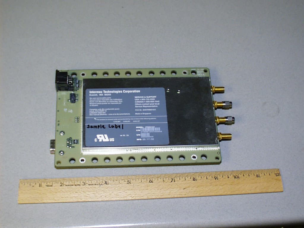
Click to zoom
Application Details
- Equipment Class
- DSS - Part 15 Spread Spectrum Transmitter
- Date of Grant
- Dec 01, 2004
- Application Purpose
- Original Equipment
- Date of Application
- Dec 01, 2004
- Equipment Note
- Intellitag RFID Radio
- Frequency Range
- 902.50000000 - 927.50000000
- Country
- United States
Documents & Files
Document Text
Text extracted from the exhibit documents filed with the FCC. Open a document above to read the original.
Users Manual
Installation and IM5 Reader Module Quick Start Guide 2IM5 Reader Module Installation and Quick Start Guide Packing List Checktoensurethatyoureceivetheseitems: SIntermec R IM5 Reader Module SCompliance Statement SWarranty Card Host Communication Host communication comes through the 9-pin female D-sub connector. RS-232 standards are supported as ordered from the factory or service center. SThe maximum data rate is 115.2K baud, with 8 data bits, no parity bit, and 1 stop bit. SThe maximum RS-232 distance from the reader to the host, modem, or other physical controller interface is 50 feet (15.2 meters). RS-232 Connections Pin NumberDefinition 2TXD (Transmit Data) to the host 3RXD (Receive Data) from the host 5Ground 7CTS (Clear to Send) from the host 8RTS (Request to Send) to the host Power Requirements Power comes in from 8 to 10 volts DC. Your 915 MHz Reader uses less than 2.4 amps. Intermec supplies 9 volts DC at 2.4 amps from Intermec power supply, p/n: 851-067-001. 3 IM5 Reader Module Installat ion and Quick Start Guide User I/O A general purpose I/O (Input/Output) connector provides sig- nal lines in and out of the reader allowing monitoring and/or control of external devices or functions. Theconnectorforthisisa13-pinfemalecircularDIN.The mating male connector you need for mating with this is an In- termec p/n: 351-184-001. I/OPin-outs Pin NumberDefinition 1GPIO IN0 2GPIO IN1 3GPIO IN2 4GPIO IN3 5GPIO OUT0 6GPIO OUT1 7GPIO OUT2 8GPIO OUT3 9 through 13Ground through individual 10 ohm resistors Outputs and inputs have 12 volt transient suppression devices to ground at the connector. Output signals are driven by 2N3904 NPN transistors (low level) with a 100 kohm pull-up to +5 volts through a silicon diode, giving about a 4.3 volt high level. An output can be pulled high from an external source as high as 12 volts. This will however tend to pull the other out- puts higher (through two 100k resistors). The low level will be about0.1voltuptoabout30mA.Theoutputlowvoltagewill climb higher as the sink current increases. There is no protection on this. You need to ensure that their load won’t require the reader to sink more than 50 mA. Input signals should be 0 to +1.5 volt for a low input and +3.5 to +5 volts for a high input. Each input has a 1.1 kohm resistor in series with clamping diodes, but only about 1μAisusedun- til the input exceeds the 0 to +5 volt input range. There is also a weak (100 kohm) pull-up to +5 volt on each input. 4IM5 Reader Module Installation and Quick Start Guide Installing the IM5 Reader Module The IM5 Reader Module requires 8-10 volts DC at 2 amps. The IF4 Serial Reader is powered through a 2-pin bulkhead bar- rel connector (Switchcraft p/n: 712A). The Reader Module supplies 9-volt 2.4 amps to this connector. Mating plugs for this connector are Switchcraft part numbers 760, 760K or 761K. A cable within the PSR connects the bulk- head barrel connector, via an endplate switch, to the 2-pin Mo- lex connector on the IM5 Reader Module. IM5 Reader module Cable connector Auxiliary I/O Connector RS-232 port The IM5 Reader Module has holes along the sides that can be used for mounting. For best results, attach heat sink to case via the screwholes in the heat sink. Screw holes IM5 Reader module 5 IM5 Reader Module Installat ion and Quick Start Guide Connecting and Getting Started FCC and Industry Canada regulations limit exposure to radiofrequency (RF) radiation. To comply with these regulations, operators of this device must maintain a distance of at least 23 cm. (9.1 inches) from the cover on the antenna assembly (The cover on the antenna is the dome shaped surface). While the device is on, the operator’s body and parts of the body such as eyes, hands, or head, must be 23 cm. (9.1 inches) or farther from the cover of the antenna assembly. FCC and Industry Canada regulations also require that the antenna assembly of this device be installed in accordance with the installation procedures to allow the operator to comply with the limit. Use of antennas andaccessories not authorized may void the compliance of this product and may result in RF exposures beyond the limits established for this equipment. 6IM5 Reader Module Installation and Quick Start Guide Antenna Installation 1Connect the antenna cable to a port. The four antenna con- nectors have lock washers and nuts to allow for panel mount- ing. 2Connect a reverse SMA terminator (Intermec p/n 345-004-001) to any port that does not have an antenna at- tached. Each port must have either an antenna or a terminator connected. Do not apply power to the Reader unless an antenna cable or terminator is installed on each antenna port. Antenna ports (4) Washers (4) Nuts (4) Reverse SMA terminator Reverse SMA Antenna cable Reader LED Explanation LEDMeaning 0Power On 1Reader communicating with host, LED flashes as data transfer occurs. 2Reader searching for tags 3Reader communicating with a tag, LED flashes as transfer occurs. 7 IM5 Reader Module Installat ion and Quick Start Guide Troubleshooting Troubleshooting Doesn’t Recognize Tag 1. Ensure antenna is properly connected. 2. Ensure reader is connected to your computer. 3. Ensure computer is plugged into AC outlet and computer is On. 4. Ensure tag is within range of antenna. 5. Call Intermec Technical Support 1-800-755-5505 (option 2). Product Specifications Dependent upon operating conditions and demands expected. If used in a normal office environment with good read conditions, you could expect to read up to 60 tags per second. Tags located too far away or in poor locations, with respect to interfering objects, provides poor results. Firmware Architecture FirmwareSpec Detail Protocol/CompatibilityCommunicates in three modes: Ap- plication Peripheral Interface (API) and Basic Reader Interface (BRI).ANSI CCITS 256.2000 for API, part 2, part 3-1 General Specifications ReceiverSpec Detail ProtocolISO 180006B Tag data rates32 kbps TransmitterSpec Detail ProtocolIntellitag Transmitter type…
Text truncated - open the document above for the full version.
Users Manual
578-100-102 Revision B Page 1 of 3 *578-100-102B* *578-100-102B* Compliance Statement Insert Device Name: RFID Reader Module Model Number: Model IM5 The responsible party for the compliance of this device is: Intermec Technologies Corporation 6001 36 th Avenue West Everett, WA 98203 USA (425) 348-2600 This product conforms to the following approvals. The user(s) of this product are cautioned to use accessories and peripherals approved by Intermec Technologies Corporation. The use of accessories other than those recommended, or changes to this product that are not approved by Intermec Technologies Corporation, may void the compliance of this product and may result in the loss of the users authority to operate the equipment. This device complies with Part 15 of the FCC Rules. Operation is subject to the following two conditions: (1) This device may not cause harmful interference, and (2) this device must accept any interference received, including interference that may cause undesired operation. FCC Digital Emissions Compliance This equipment has been tested and found to comply with the limits for a Class B digital device, pursuant to Part 15 of the FCC Rules. These limits are designed to provide reasonable protection against harmful interference in a residential installation. This equipment generates, uses and can radiate radio frequency energy and, if not installed and used in accordance with the instructions, may cause harmful interference to radio communications. However, there is no guarantee that interference will not occur in a particular installation. If this equipment does cause harmful interference to radio or television reception, which can be determined by turning the equipment off and on, the user is encouraged to try to correct the interference by one or more of the following measures: • Reorient or relocate the radio or television receiving antenna. • Increase the separation between the computer equipment and receiver. • Connect the equipment into an outlet on a circuit different from that to which the radio or television receiver is connected. • Consult the dealer or an experienced radio television technician for help. Canadian Digital Apparatus Compliance This Class B digital apparatus meets all requirements of the Canadian Interference-Causing Equipment Regulations. Cet appareil numérique de la classe B respecte toutes les exigences du Règlement sur le matériel brouilleur du Canada. WARNING: Per the FCC and Canada radio frequency (RF) exposure requirements, (1) Antennas must be supplied and installed as recommended by Intermec Technologies Corporation to insure compliance to RF exposure requirements. The antennas approved for use are Intermec part numbers 805-619-001 and 805-628-001. Correct antenna mounting is fully described within the Intermec IM5 Users Guide. (2) When installing and using Intermec approved remote antennas associated the RFID tag reader, a 23-cm (9.1-inch) passing distance must be maintained from any body part of the user or nearby persons and the remote antenna. The antenna must not be touched during transmitter operation. (3) Cables attached to the remote antennas must have a minimum length as provided from Intermec to insure the proper losses to control RF exposure. (4) RF safety requirements mandate this device cannot be co-located with other transmitters. This radio is approved as a “module.” Therefore, the unit can be placed within any enclosure for use. As an approved module, the following restrictions apply: 1. The module must use the Intermec-approved antennas. 2. The unit must display “Contains TX FCC ID: EHA-xxxxxxx” with xxxxxx designating the FCC ID of the IM5 module, per the labeling requirements of Parts 2 and 15 of the FCC rules. 3. The power supply used with the module must be the Intermec unit tested with the module or the integrator must verify that their supply meets the FCC class B emissions limits when used with this module. 4. Integrators are responsible for insuring that the unintentional emissions of the resulting system meets the requirements of Par t 15 of the FCC rules. If any system integrator wishes to make changes, use their own antennas, or change the FCC ID, they will have to follow Parts 2 and 15 of the FCC rules for changes to a radio with module approval. Any changes to Intermec approved equipment will require proper notification to the FCC. 578-100-102 Revision B Page 2 of 3 *578-100-102B* *578-100-102B* DECLARATION OF CONFORMITY (According to ISO/IEC Guide 22 and EN 45014) PAGE ONE OF ONE THE PRODUCT HEREWITH COMPLIES WITH THE REQUIREMENTS OF : THE LOW-VOLTAGE DIRECTIVE 73/23/EEC. THE EMC DIRECTIVE 89/336/EEC. THE R&TTE DIRECTIVE 1999/05/EC. Manufacturer’s Name: European Representative: Intermec Technologies Corporation Intermec International Incorporated 6001 36 th Avenue West Sovereign House, Vastern Road Everett, WA 98203 Reading, Berkshire RG1 8BT England Declares that the product listed below: Product Type: ITE/Residential, Commercial, and Light Industrial Product Name: Model IM5 Model Number: Model IM5 Options: All Beginning Serial Number: All Date Issued: August 31, 2004 Conforms to the following product specifications: Safety: IEC 60950-1 / EN 60950-1 EMC: EN 55022 : 1998 / CISPR Publication 22 : 1997, Class B Limits and Methods EN 55024 : 1998 (CISPR 24) Information Technology Equipment – Immunity Characteristics – Limits and Methods of Measurement EN 61000-4-2 : 1995 – Electrostatic Discharge EN 61000-4-3 : 1995 – Radiated RF Field EN 61000-4-4 : 1995 – Electrical Fast Transients EN 61000-4-5 : 1995 – Voltage Surge EN 61000-4-6 : 1996 – Conducted RF Field EN 61000-4-8 : 1995 – Magnetic Field EN 61000-4-11 : 1994 – Voltage Dips, Short Interruptions, and Variations EN61000-3-2 : 1995 + A1 : 1998 + A2 : 1998 + A14 : 2000 – Harmonic Current Emissions EN61000-3-3 : 1994 – Voltage Fluctuation and Flicker Radio: ETSI EN 302 208-2 ETSI EN 300 220-2 I, the undersigned, hereby declare that the equipment specified a…
Text truncated - open the document above for the full version.
Cover Letter(s)
6001 36 th Avenue West Everett, Washington 98203 United States tel 425.348.2600 fax 425.355.9551 www.intermec.com 3-NOV-2004 Federal Communications Commission Authorization and Evaluation Division 7435 Oakland Mills Road Columbia, Maryland 21046 To whom it may concern, The IM5 RFID reader module, FCC ID: EHARFID915IM5 , is seeking FCC Authorization as a modular transmitter. The EUT meets the requirements for modular approval as detailed in FCC public Notice DA00-1407. Compliance to each of the requirements is described below: 1. “The modular transmitter must have its own RF shielding.” - The radio portion of the IM5 wireless module has its own RF shielding. The shielding is installed at the factory. 2. “The modular transmitter must have buffered modulation/data inputs.” - Please see Appendix 1 for schematics of the module. 3. “The modular transmitter must have its own power supply regulation.” - The EUT has its own voltage regulation circuitry. Please see Appendix 1 for schematics of the module. 4. “The modular transmitter must comply with the antenna requirements of section 15.203 and 15.204(c).” - The EUT meets the FCC antenna requirements. 5. “The modular transmitter must be tested in a stand-alone configuration.” - The EUT was tested in a stand-alone configuration. 6. “The modular transmitter must be labeled with its own FCC ID number.” - The EUT is labeled with its own FCC ID number. 7. “The modular transmitter must comply with any specific rule or operating requirements applicable to the transmitter and the manufacture must provide adequate instruction along with the module to explain any such requirements.” - The EUT is compliant with all applicable FCC rules. 8. “The modular transmitter must comply with any applicable RF exposure requirements.” – The EUT fully complies with RF exposure requirements. Yours truly, Scott J. Holub Regulatory Compliance Engineer III Intermec Technologies Corporation 550 Second Street S.E. Cedar Rapids, IA 52401 USA
Cover Letter(s)
6001 36 th Avenue West Everett, Washington 98203 United States tel 425.348.2600 fax 425.355.9551 www.intermec.com 13-DEC-2004 CONFIDENTIALITY REQUEST CONTAINED WITHIN Federal Communications Commission Authorization and Evaluation Division 7435 Oakland Mills Road Columbia, Maryland 21046 Re: Application for Frequency Hopping Spread Spectrum Transceiver Certification To whom it may concern, Application: Intermec Technologies Corporation, 550 Second Street SE, Cedar Rapids, Iowa 52401-2029 herein submits for Certification of a Frequency Hopping Spread Spectrum Transceiver FCC ID: EHARFID915IM5. Intermec is also the manufacturer of this equipment. Confidentiality: Pursuant to Section 0.459 of the Commission's rules (CFR 47), Intermec requests confidentiality for portions of the material contained in this application and that the identified material be withheld from public inspection following the grant of this authorization. This material contains Intermec trade secrets and confidential information that Intermec does not customarily release to the public and which is otherwise not generally available to the pubic. Confidentiality is requested for the following exhibits: • Theory of Operation • Schematics • Parts Placement • Block Diagram Description: This equipment is an RFID reader radio module, which operates in the 902-928 MHz band. Limited modular approval is requested since the radio design allows use in multiple hosts of various configurations. Contact Information: Please contact me by telephone at (319) 369-3865 or by e-mail ([email protected]) if there are questions or additional information needed concerning this filing. Yours truly, Scott J. Holub Regulatory Compliance Engineer III Intermec Technologies Corporation 550 Second Street S.E. Cedar Rapids, IA 52401 USA
External Photos
EXHIBIT C - EUT EXTERNAL PHOTOGRAPHS EUT (IM5) Board Top with Shielding View EUT (IM5) Board Bottom With Shielding View Adapter View I Adapter View II M17/28-RG058 MIL – C – 17 Cable M17/60 –RG142 MIL – C – 17G Cable
ID Label/Location Info
EXHIBIT A - FCC ID LABEL INFORMATION Proposed FCC ID Label Specifications: Text is black or white in color and is left justified. Labels are silk- screened and shall be “permanently affixed” at a conspicuous location on the EUT. Proposed Label Location on EUT Bottom View of EUT/FCC ID Label FCC ID: EHARFID915IM5 This device complies with Part 15 of the FCC Rules. Operation is subject to the following two conditions: (1) this device may not cause harmful interference, and (2) this device must accept any interference received,
Internal Photos
EXHIBIT C - EUT INTERNAL PHOTOGRAPHS EUT (IM5) Board Top Without Shielding View EUT (IM5) Board Bottom With VCO Shielding View EUT (IM5) Board Bottom Without Shielding View
Operational Description
Cable Specification: Model Length Attenuation M17/28 – RG058 MIL-C-17 4 m 2.3 dB M17/60 – RG142 MIL – C – 17G 2 m 1.2 dB
Operational Description
Antennas Intermec part number 805-609-001 Cushcraft Circular Polarized Panel Antenna with factory attached 13 feet of RG58 cable, TNC connector (TNC to SMA adaptor provided), 7dBic gain (production version will have reverse N connector) A270001-01 Sinclair vertical polarized linear dipole antenna, N connector, 5dBd gain (7.1dBi) (production version will have reverse N connector) 805-622-001 Kathrein Circular Polarized Panel Antenna, SMA connector (SMA to N adaptor provided), 9dBic gain (production version will have reverse N connector) xxx-xxx-xxx Huber Suhner vertical polarized linear planar antenna, N connector, 8dBi gain (production version will have reverse N connector) ITA915017 Intermec Programming Antenna Assembly (low gain) (black box), N connector IMPORTANT Since measurement differences can occur when measuring power; it is requested that the first parameter to be measured is the Transmitter output power conducted and radiated. If the power level needs to be adjusted to meet the specifications, the adjustment is made via the test application and the new level will be stored in non-volatile RAM. See Adjusting Tx Power section of the operating instructions.
Test Report
Note: The test report is specially limited to the above company and the product model only. It may not be duplicated without prior written consent of Bay Area Compliance Laboratory Corporation. This report must not be used by the client to claim product certification, approval, or endorsement by NVLAP, NIST or any agency of the US Government. FCC 15.247 EMI MEASUREMENT AND TEST REPORT For Intermec Technologies Corporation 550 Second Street SE, m/s GR05 Cedar Rapids, Iowa 52401 FCC ID: EHARFID915IM5 This Report Concerns: Original Report Equipment Type: Intellitag RFID Radio Test Engineer: Ming Jin Report No.: R0410087 Test Date: 2004-10-25 Reviewed By: Daniel Deng / Prepared By: Bay Area Compliance Laboratory Corporation (BACL) 230 Commercial Street Sunnyvale, CA 94085 Tel: (408) 732-9162 Fax: (408) 732 9164 Intermec Technologies Corporation FCC ID: EHARFID915IM5 Report # R0410087Rpt.doc Page 2 of 39 FCC 15.247 Report TABLE OF CONTENTS Intermec Technologies Corporation ............................................................................................................................1 GENERAL INFORMATION.......................................................................................................................................4 PRODUCT DESCRIPTION FOR EQUIPMENT UNDER TEST (EUT) ....................................................................................4 OBJECTIVE...................................................................................................................................................................4 RELATED SUBMITTAL(S)/GRANT(S).............................................................................................................................4 TEST METHODOLOGY..................................................................................................................................................4 TEST FACILITY.............................................................................................................................................................4 SYSTEM TEST CONFIGURATION ..........................................................................................................................6 JUSTIFICATION.............................................................................................................................................................6 BLOCK DIAGRAM.........................................................................................................................................................6 EQUIPMENT MODIFICATIONS.......................................................................................................................................6 SUPPORT EQUIPMENT LIST AND DETAILS....................................................................................................................6 POWER SUPPLY INFORMATION.....................................................................................................................................6 INTERFACE PORTS AND CABLING.................................................................................................................................6 CONFIGURATION OF TEST SYSTEM..............................................................................................................................7 TEST SETUP BLOCK DIAGRAM.....................................................................................................................................7 SUMMARY OF TEST RESULTS FOR FCC PART 15............................................................................................8 ANTENNA REQUIREMENT ......................................................................................................................................9 §15.207(A) - CONDUCTED EMISSION...................................................................................................................10 MEASUREMENT UNCERTAINTY..................................................................................................................................10 TEST SETUP................................................................................................................................................................10 SPECTRUM ANALYZER SETUP....................................................................................................................................10 TEST EQUIPMENT LIST AND DETAILS.........................................................................................................................10 TEST PROCEDURE......................................................................................................................................................10 ENVIRONMENTAL CONDITIONS..................................................................................................................................11 SUMMARY OF TEST RESULTS.....................................................................................................................................11 CONDUCTED EMISSIONS TEST DATA.........................................................................................................................11 PLOT OF CONDUCTED EMISSIONS TEST DATA...........................................................................................................11 §15.205 & §15.209 - RADIATED EMISSION...........................................................................................................14 MEASUREMENT UNCERTAINTY..................................................................................................................................14 TEST SETUP................................................................................................................................................................14 SPECTRUM ANALYZER SETUP....................................................................................................................................14 T…
Text truncated - open the document above for the full version.
Test Setup Photos
EXHIBIT B - TEST SETUP PHOTOGRAPHS Conducted Emission Radiated Emission, EUT & Antenna 7.1dBi Vertical Polarized Dipole Radiated Emission, EUT& Antenna 8dbi Vertical Polarized Planar Radiated Emission, EUT & Antenna 9dBi Circular Polarized Panel Radiated Emission, EUT (module) with Load / Notebook, CW mode
Contact Information
Applicant
Brian Rudick(VP & GC, Honeywell Scanning & Mobility)
Test Firm
Bay Area Compliance LaboratoryJohn Chan
Technical Specifications
| # | Rule Parts | Frequency Range | Power Output |
|---|---|---|---|
| 1 | 15C | 902.5 MHz - 927.5 MHz | 1 W |
Other Applications from Intermec Technologies Corporation
EHA-1015CP01X1
Sep 29, 20131015CP01
Equipment Class
NII - Unlicensed National Information Infrastructure TX
EHA-1015CP01SX1
Sep 08, 20131015CP01S
Equipment Class
PCE - PCS Licensed Transmitter held to ear
EHA-RC12ABGN
Aug 19, 2013WLAN board
Equipment Class
DSS - Part 15 Spread Spectrum Transmitter
EHA-1000CP01F
Feb 19, 20131000CP01F9, 1000CP02F9, 1001CP01F9
Equipment Class
DTS - Digital Transmission System
EHA-INBT02
Dec 11, 2012BT Board
Equipment Class
DSS - Part 15 Spread Spectrum Transmitter