ELY547-47-1012E-RTranceiver Module
Jeckson Electric Co., Ltd
Click to zoom
Application Details
- Equipment Class
- DXX - Part 15 Low Power Communication Device Transmitter
- Date of Grant
- Nov 01, 2011
- Application Purpose
- Original Equipment
- Date of Application
- Oct 31, 2011
- Equipment Note
- Tranceiver Module
- Frequency Range
- 2402.00000000 - 2480.00000000
- Company
- Jeckson Electric Co., Ltd
- Country
- Hong Kong
Documents & Files
Document Text
Text extracted from the exhibit documents filed with the FCC. Open a document above to read the original.
Users Manual
1 Owner's Manual WIRELESS REMOTE SWITCH MODEL: 47-1012E-R FCC ID: ELY547-47-1012E-R IC 1492A-471012ER FLAME/HEAT ON/OFF BUTTON Press the Flame/Heat On/Off button to turn the Flame/Heat function ON or OFF. When the heater function is ON, the icon is displayed on the remote control in the upper left hand corner. When this icon is displayed, the red indicator light is activated on the firebox. NOTE When using the remote control the heater runs on a thermostat. Press the or direction keys to adjust the set temperature. Once the desired set temperature is reached the heater will turn OFF. The heater will cycle ON and OFF to maintain the desired set temperature. PURIFIRE ON/OFF BUTTON Press the Purifire™ On/Off button to turn the Purifire™ function ON or OFF. When the Purifire™ function is ON and the Heater icon is NOT displayed on the remote control, the green indicator light is activated on the firebox. NOTE To turn the Flame/Heat and Purifire™ ON or OFF at the same time, press both control buttons simultaneously. DIMMER Press the left “-“ or right “+” direction button to decrease or increase the brightness of the upper lights. NOTE The bar graph located on the display screen indicates the upper light brightness range. FLAME SPEED Press the left “-“ or right “+” direction buttons to decrease or increase the flame speed. NOTE The bar graph located on the display screen indicates the speed range of the flame. 2 COUNTDOWN TIMER To set the Countdown timer, press the left “-“ or right “+” direction buttons to decrease or increase by 30 minute decrements or increments. The countdown timer can be set from 30 minutes to 8 hours. The fireplace will automatically turn OFF when the sleep timer reaches 0 minutes. PURIFIRE SPEED The Purifire™ includes a high efficiency filter to help improve the quality of air. When the Purifire™ function is ON, the green indicator light is activated on the firebox. Press the left “-“ or right “+” direction buttons to select LOW or HIGH. NOTE The Purifire™ can also be turned On/Off by pressing the Purifire™ On/Off button. SET TEMPERATURE Press the “-“ or right “+” direction button together of to select between °F and °C. Press the “-“ or right “+” direction button to decrease or to increase temperature. 3 INITIALIZING THE REMOTE CONTROL 1. Plug cord into 120 volt wall outlet. 2. Set the 3 position manual control to Position 1 (left position). 3. Press and hold the initialization button on the Switch Power. 4. While holding the initialization button, press the flame ON/OFF button or the Purifire™ ON/OFF button on the remote control transmitter. 5. Release the initialization button on the Switch Board. The remote control is now ready for operation. Switch Board Panel CAUTION 1. For indoor use in dry areas only. 2. 120 volt AC supply. 4 WARNING! This OEM module is to be installed only in Dimplex North America Limited end products by Dimplex North America Limited personnel, and shall not be offered to 3rd party OEM integrators or the general public. NOTE: This equipment has been tested and found to comply with the limits for a Class B digital device, pursuant to Part 15 of the FCC Rules. These limits are designed to provide reasonable protection against harmful interference in a residential installation. This equipment generates uses and can radiate radio frequency energy and, if not installed and used in accordance with the instructions, may cause harmful interference to radio communications. However, there is no guarantee that interference will not occur in a particular installation. If this equipment does cause harmful interference to radio or television reception, which can be determined by turning the equipment off and on, the user is encouraged to try to correct the interference by one of the following measures: - Reorient or relocate the receiving antenna. - Increase the separation between the equipment and receiver. - Connect the equipment into an outlet on a circuit different from that to which the receiver is connected. - Consult the dealer or an experienced radio/TV technician for help. This device complies with Part 15 of the FCC Rules. Operation is subject to the following two conditions: (1) This device may not cause harmful interference, and (2) this device must accept any interference received, including interference that may cause undesired operation. FCC Caution: Any changes or modifications not expressly approved by the party responsible for compliance could void the user's authority to operate this equipment. The RF Module is labeled with its own FCC ID Number and the FCC ID is not visible when the module is installed inside the end product. The outside of the device into which the module is installed will display a label referring to the enclosed module. This exterior label will as the following: Contains Transmitter Module FCC ID: ELY547-47-1012E-R This device complies with part 15 of the FCC Rules. Operation is subject to the following two conditions: (1) this device may not cause harmful interference, and (2) this device must accept any interference received, including interference that may cause undesired operation. 5 This device complies with Industry Canada licence-exempt RSS standard(s). Operation is subject to the following two conditions: (1) this device may not cause interference, and (2) this device must accept any interference, including interference that may cause undesired operation of the device. Le présent appareil est conforme aux CNR d'Industrie Canada applicables aux appareils radio exempts de licence. L'exploitation est autorisée aux deux conditions suivantes : (1) l'appareil ne doit pas produire de brouillage, et (2) l'utilisateur de l'appareil doit accepter tout brouillage radioélectrique subi, même si le brouillage est susceptible d'en compromettre le fonctionnement. Under Industry Canada regulations, this radio transmitter may only operate using an antenna of a type and maximum (or lesser) gain approved for the transmitter by Indu…
Text truncated - open the document above for the full version.
External Photos
Photographs of EUT Front View of the product Rear View of the product
Internal Photos
Label location
Test Report
TEST REPORT No: (5211)239-0019 BUREAU VERITAS HONG KONG LIMITED – Kowloon Bay Office 1/F Pacific Trade Centre, 2 Kai Hing Road, Kowloon Bay, Kowloon,HONG KONG Tel: +852 2331 0888 Fax: +852 2331 0889 www.cps.bureauveritas.com This report is intended for your exclusive use. Any copying or replication of this report to or for any other person or entity, or use of our name or trademark, is permitted only with our prior written permission. Our report is limited to the test samples identified herein. The results set forth in this report are not necessarily indicative or representative of the statistical quality or characteristics of the lot from which a test sample was taken or any similar or identical product unless specifically and expressly noted. Our report includes all of the tests requested by you and the results thereof. You shall have thirty days from receipt of this report to request additional testing of the samples or to notify us of any errors or omissions relating to our report, provided, however, such notice shall be in writing and shall specifically address the issue you wish to raise. A failure to raise such issue within the prescribed time shall constitute your unqualified acceptance of the completeness of this report, the tests conducted and the correctness of the report contents. Page 2 of 31 Location of the test laboratory Radiated and Conducted emissions measurements are investigated and taken pursuant to the procedures of ANSI C63.4 – 2003. An Open Area Test Site and Full Anechoic Chamber (FCC Listed Site, Registration No. 642151) are set up for investigation and located at : BUREAU VERITAS HONG KONG LIMITED, EMC CENTRE No. 2106-2107, 21/F., Westin Centre, 26 Hung To Road, Kwun Tong, Kowloon, Hong Kong List of measuring equipment Radiated Emission EQUIPMENT MANUFACTURER MODEL NO. SERIAL NO. CALIBRATION DUE EMI TEST RECEIVER R&S ESCI 100379 05-SEP-2012 LOOP ANTENNA ETS-LINDGREN 6502 00102266 12-MAY-2012 BILOG ANTENNA SCHAFFNER CBL6112D 25229 16-SEP-2012 OPEN AREA TEST SITE BVCPS N/A N/A 07-JUL-2012 ANECHOIC CHAMBER ALBATROSS M-CDC 80374004499B 26-OCT-2011 COAXIAL CABLE SUHNER N/A N/A 18-SEP-2012 Conducted Emission EQUIPMENT MANUFACTURER MODEL NO. SERIAL NO. CALIBRATION DUE EMI TEST RECEIVER R&S ESCS30 830986/030 13-DEC-2011 LISN R&S ENV216 100024 12-APR-2012 Remarks:- N/A : Not Applicable or Not Available The measurement instrumentation uncertainty would be taking into consideration on each of the test result TEST REPORT No: (5211)239-0019 BUREAU VERITAS HONG KONG LIMITED – Kowloon Bay Office 1/F Pacific Trade Centre, 2 Kai Hing Road, Kowloon Bay, Kowloon,HONG KONG Tel: +852 2331 0888 Fax: +852 2331 0889 www.cps.bureauveritas.com This report is intended for your exclusive use. Any copying or replication of this report to or for any other person or entity, or use of our name or trademark, is permitted only with our prior written permission. Our report is limited to the test samples identified herein. The results set forth in this report are not necessarily indicative or representative of the statistical quality or characteristics of the lot from which a test sample was taken or any similar or identical product unless specifically and expressly noted. Our report includes all of the tests requested by you and the results thereof. You shall have thirty days from receipt of this report to request additional testing of the samples or to notify us of any errors or omissions relating to our report, provided, however, such notice shall be in writing and shall specifically address the issue you wish to raise. A failure to raise such issue within the prescribed time shall constitute your unqualified acceptance of the completeness of this report, the tests conducted and the correctness of the report contents. Page 3 of 31 Equipment Under Test [EUT] Description of Sample: Model Name: 2.4GHz Midline Remote Model Number: 47-1012E-R Rating: 100-240Va.c., 50/60Hz, 12W Description of EUT Operation: The Equipment Under Test (EUT) is a JECKSON ELECTRIC CO., LTD. of Remote Control Transceiver. It is a transceiver and operating at 2402MHz to 2480MHz. The lowest, middle and highest frequencies were tested and the results are shown in the report. The EUT transmit while signal is being received, Modulation by IC, and type is FHSS. The transceiver has the control: The Midline Remote composes of 2 modules. One is the remote control unit (Transmitter) and the other is the power switch unit (Receiver). The receiver is operated by DC8V and there is AC120V at the Relays output part (K1- K3). It consists of several parts, including 2.4GHz RF transceiver with MPU controller, driver and output relays. When a signal is received through the antenna, the original encoded signal will then be retrieved by the RF transceiver Module and then be decoded a correct signal to make or break the relay contacts through the Driver in order to open or close the desired output in the Output stage(s). Antenna Requirement (Section 15.203) The EUT is use of a permanently antenna. It is PCB trace antenna. The antenna is not replaceable or user serviceable. The requirements of S15.203 are met. There are no deviations or exceptions to the specifications. TEST REPORT No: (5211)239-0019 BUREAU VERITAS HONG KONG LIMITED – Kowloon Bay Office 1/F Pacific Trade Centre, 2 Kai Hing Road, Kowloon Bay, Kowloon,HONG KONG Tel: +852 2331 0888 Fax: +852 2331 0889 www.cps.bureauveritas.com This report is intended for your exclusive use. Any copying or replication of this report to or for any other person or entity, or use of our name or trademark, is permitted only with our prior written permission. Our report is limited to the test samples identified herein. The results set forth in this report are not necessarily indicative or representative of the statistical quality or characteristics of the lot from which a test sample was taken or any similar or identical product unless specifically and expressly noted. Our report includes all of the tes…
Text truncated - open the document above for the full version.
Test Setup Photos
Conducted Emission Test Set Up Radiated Emission Test Set Up
Contact Information
Applicant
Henry Chan(Senior Electronic Engineer)
Test Firm
Bureau Veritas Hong Kong LimitedSteven Tsang
[email protected]85223310728
Technical Specifications
| # | Rule Parts | Frequency Range | Power Output |
|---|---|---|---|
| 1 | 15C | 2.40 GHz - 2.48 GHz | - |
Other Applications from Jeckson Electric Co., Ltd
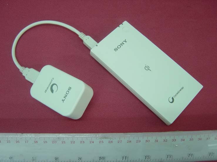
ELY547-CP-W5
Feb 23, 2014Wireless Portable Charger
Equipment Class
DCD - Part 15 Low Power Transmitter Below 1705 kHz
ELY547-36-0029-R
Oct 16, 2013Transceiver Module
Equipment Class
DXX - Part 15 Low Power Communication Device Transmitter
ELY547-47-1012E-T
Oct 12, 2011Remote Controller
Equipment Class
DXX - Part 15 Low Power Communication Device Transmitter
ELY547-47-1004J-R
Nov 25, 20073-Stage On/Off Remote with EEPROM (433MHz Rx)
Equipment Class
CRR - Superregenerative Receiver
ELY547-47-1020
Nov 12, 2007RF Wireless Remote Switch (433MHz Rx)
Equipment Class
CRR - Superregenerative Receiver