ELY547-CP-W5Wireless Portable Charger
Jeckson Electric Co., Ltd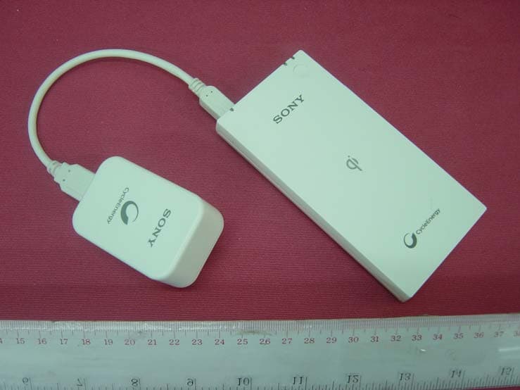
Click to zoom
Application Details
- Equipment Class
- DCD - Part 15 Low Power Transmitter Below 1705 kHz
- Date of Grant
- Feb 23, 2014
- Application Purpose
- Original Equipment
- Date of Application
- Feb 20, 2014
- Equipment Note
- Wireless Portable Charger
- Frequency Range
- 0.11100000 - 0.20500000
- Company
- Jeckson Electric Co., Ltd
- Country
- Hong Kong
Documents & Files
Document Text
Text extracted from the exhibit documents filed with the FCC. Open a document above to read the original.
Users Manual
CP-W5 0904-390-00301A US/ES CP-W5 0904-390-00301A US/ES Supplying power using wireless power supply 1. Connect the micro USB connector of the USB cable to the micro USB input port of the unit and connect the other end of the USB cable to the USB port of AC adaptor. 2. Plug AC adaptor into a wall outlet, holding the AC adaptor. The orange LED indicator turns on. Refer to “Troubleshooting” if the orange LED indicator turns off a few minutes later or does not turn on. 3. Press the button on the unit and Red LED indicator turns on. The red LED indicator turns on, and the unit starts to ready to supply power. The orange LED indicator flashes depending on the remaining power. 4. Quickly put your device on the unit. The unit detects your device and supply the power. Then the colors of LED indicator change from red to blue. Wireless charging cannot be done when the coil between the receiver and the transmitter is off center. Make sure the LED color change from Red to Blue and your device is charged. While your device is charged, the Blue LED turns on until your device finished charging. Supplying power using the USB cable In order to supply power to the portable device, a USB charging cable is required (not supplied). Please check the portable device for specific pin connection. USB Type-A is required for the unit. 1. Connect the micro USB connector of the supplied USB cable to the micro USB input port of the unit and connect the other end of the supplied USB cable to the USB port of AC adaptor. 2. Connect a USB charging cable (officially supported by the portable device) to the portable device. 3. Connect the other end of the cable to the USB port of the unit. 4. Plug AC adaptor into a wall outlet, holding the AC adaptor. The orange LED indicator turns on. Refer to “Troubleshooting” if the orange LED indicator turns off a few minutes later or does not turn on. 5. Press the button on the unit. The green LED indicator turns on, and the unit starts supplying power. The orange and green LED indicators turn on, and charging the unit and supplying power to a portable device start. Power supply stops automatically when the portable device is fully charged. If you want to stop the power supply, press the button on the portable power supply. Charging Time Built-in BatteryCharging Time 3.7 V (typ. 5,000 mAh / min. 4,880 mAh) Approx. 4 hours (from 1.5 A AC Adaptor) Approx. 11 hours (from standard USB port) Recharging using a USB output AC adaptor rated at 5 V 0.5 A or greater is possible. Please note that this product’s maximum input current is 1.5 A. Supply Time OutputSupply Time USB output: 5 V, 1.5 AApprox. 120 minutes Supply time varies depending on battery condition, storage condition and portable device. Specifications Input DC 5 V Output USB: DC 5 V, 1.5 A (Max.) Dimensions 66.0 mm × 130.0 mm × 16.5 mm (2 5/8 inches × 5 1/8 inches × 21/32 inches) (W/H/L) Weight Approx. 188 g (6.6 oz) Operating temperature 32 °F - 95 °F (0 °C - 35 °C) Design and specifications are subject to change without notice. Troubleshooting The unit cannot be charged. When the PC is in sleep mode, you cannot charge the unit. Recover the PC from the sleep mode. When it takes time for USB authentication, plug in and out the USB cable from the PC, and try again. The orange LED indicator does not turn on. The usage environment is out of operating temperature range. Use in the operating temperature range. There is a bad connection in the micro USB input port. Clean the micro USB input port. The orange LED indicator flashes quickly. Charging is abnormal. Stop use. Contact your Sony dealer or authorized Sony service facility. Charging time of the unit is short [charging takes less than 4 hours (from AC adaptor) or 11 hours (from standard USB port)]. The unit has reached the end of its service life or is malfunctioning. When the supply time is extremely short even when the unit is fully charged, the unit has reached the end of its service life. Purchase a new product (service life varies depending on use). If a malfunction occurs, contact your Sony dealer or authorized Sony service facility. The usage environment is out of operating temperature range. Use in the operating temperature range. The unit cannot supply power to a portable device, or the green LED or blue LED indicator does not turn on. * * * Supplying power using the USB cable The USB cable between the unit and the portable device is connected incorrectly. Connect the USB cable correctly. The usage environment is out of operating temperature range. Use in the operating temperature range. The remaining battery capacity is low. Charge the unit. The portable device is not in charging mode. Check and set up the portable device in charging mode. Turn the portable device on before charging. Supplying power using wireless power supply The device is not placed in an appropriate place. Wireless charging cannot be done when the coil between the receiver and the transmitter is off center. Check the charging status of the device, and place the device in a chargeable location, or place the device in a location so that the unit’s blue LED indicator illuminates. The placed device does not support Qi. If the device is not Qi certified, wireless power supply is unavailable. Foreign material such as a sticker may be located between the device and the unit. Remove the foreign material immediately. A cover is on the device. Remove the cover before charging. The supply time to the portable device is short. Supplying power using the USB cable The connector or USB port on the portable device is dirty. Clean it. The usage environment is out of operating temperature range. Use in the operating temperature range. The unit has reached the end of its service life or is malfunctioning. When the supply time is extremely short, even when the unit is fully charged, the unit has reached the end of its service life. Purchase a new product (service life varies depending on use). If a malfunct…
Text truncated - open the document above for the full version.
External Photos
INTERTEK TESTING SERVICE Report No.: 13120567HKG-001 Equipment Photographs Model : CP-W5 (External) FCC ID: ELY547-CP-W5
Internal Photos
INTERTEK TESTING SERVICE Report No.: 13120567HKG-001 Equipment Photographs Model : CP-W5 (Internal) FCC ID: ELY547-CP-W5 INTERTEK TESTING SERVICE Report No.: 13120567HKG-001 Equipment Photographs Model : CP-W5 (Internal) FCC ID: ELY547-CP-W5 INTERTEK TESTING SERVICE Report No.: 13120567HKG-001 Equipment Photographs Model : CP-W5 (Internal) FCC ID: ELY547-CP-W5
RF Exposure Info
- The test report only allows to be revised within the retention period unless further standard or the requirement was noticed. - This report is for the exclusive use of Intertek's Client and is provided pursuant to the agreement between Intertek and its Client. Intertek's responsibility and liability are limited to the terms and conditions of the agreement. Intertek assumes no liability to any party, other than to the Client in accordance with the agreement, for any loss, expense or damage occasioned by the use of this report. Only the Client is authorized to permit copying or distribution of this report and then only in its entirety. Any use of the Intertek name or one of its marks for the sale or advertisement of the tested material, product or service must first be approved in writing by Intertek. The observations and test results in this report are relevant only to the sample tested. This report by itself does not imply that the material, product, or service is or has ever been under an Intertek certification program. PAGE 1 OF 6 Intertek Testing Services Hong Kong Ltd. 2/F., Garment Centre, 576 Castle Peak Road, Kowloon, Hong Kong. Tel: (852) 2173 8888 Fax: (852) 2785 5487 Website: www.hk.intertek-etlsemko.com TEST REPORT Applicant: Number: 13120567HKG-003 Date: 14 Feb 2014 Jeckson Electric Co., Ltd. 18/F., China Aerospace Centre, 143 Hoi Bun Road, Kwun Tong, Kowloon, Hong Kong. Sample Description Product : Wireless Portable Charger Brand Name : Sony Model No. : CP-W5 Electrical Rating : 100 - 240VAC, 50 / 60Hz Adaptor : Model: CP-AD2, Input: 100-240VAC 50/60Hz, Output: 5VDC 2.1A Date Received : 12 Feb 2014 Date Test Conducted : 13 Feb 2014 Test Requested : Test for compliance with evaluation of environmental impact of human exposure to radiofrequency (RF) radiation according to FCC CFR47 Part 1 – 1.1307 and 1.1310 Test Method : Magnetic field strength (A/m) and Electric field strength (V/m) measurement Applied Limit : Limit for Maximum Permissible Exposure (MPE) Test Result : Pass Note : N/A Remark : N/A ************************************************ End of Page ******************************************************* Prepared and checked by: ____________________ Chow Chi Ming, Billy Manager PAGE 2 OF 6 Intertek Testing Services Hong Kong Ltd. 2/F., Garment Centre, 576 Castle Peak Road, Kowloon, Hong Kong. Tel: (852) 2173 8888 Fax: (852) 2785 5487 Website: www.hk.intertek-etlsemko.com TEST REPORT Applicant / Company: Jeckson Electric Co., Ltd. Report No.: 13120567HKG-003 Model: CP-W5 Magnetic field strength (A/m) and Electric field strength (V/m) measurement (0.3 – 3.0MHz) 1. Equipment Equipment No. Equipment Manufacturer Model No. Serial No. EW-2193 Exposure Level Meter Narda Safety ETL-400 H-0035 EW-2508 RF Electric Field Probes EMCO HI-6105USB 00090198 2. Applicable Limit Table 1 – Limits for Maximum Permissible Exposure (MPE) Frequency range (MHz) Electric field strength (V/m) Magnetic field strength (A/m) Power density (mW/cm 2 ) Averaging time (minutes) (A) Limits for Occupational/Controlled Exposures 0.3-3.0 614 1.63 *(100) 6 3.0-30 1842/f 4.89/f *(900/f 2 ) 6 30-300 61.4 0.163 1.0 6 300-1500 f/300 6 1500-100,000 5 6 (B) Limits for General Population/Uncontrolled Exposure 0.3-1.34 614 1.63 *(100) 30 1.34-30 824/f 2.19/f *(180/f 2 ) 30 30-300 27.5 0.073 0.2 30 300-1500 f/1500 30 1500-100,000 1.0 30 Note: f denotes for frequency in MHz * denotes for plane-wave equivalent power density PAGE 3 OF 6 Intertek Testing Services Hong Kong Ltd. 2/F., Garment Centre, 576 Castle Peak Road, Kowloon, Hong Kong. Tel: (852) 2173 8888 Fax: (852) 2785 5487 Website: www.hk.intertek-etlsemko.com TEST REPORT Applicant / Company: Jeckson Electric Co., Ltd. Report No.: 13120567HKG-003 Model: CP-W5 3. Result Magnetic Field (H-Field) strength at 10cm from the boundaries of the EUT Test Mode: Charging (without adaptor) Measuring DistanceMagnetic Field Limit Measurement point 1 10cm 0.73 Measurement point 2 10cm 0.90 Measurement point 3 10cm 0.98 Measurement point 4 10cm 0.82 Measurement point 5 10cm 0.87 Measurement point 6 10cm 1.03 1.63 A/m Electric Field (E-Field) strength at 10cm from the boundaries of the EUT Test Mode: Charging (without adaptor) Measuring DistanceElectric Field Limit Measurement point 1 10cm 3.00 Measurement point 2 10cm 4.27 Measurement point 3 10cm 2.90 Measurement point 4 10cm 3.94 Measurement point 5 10cm 5.40 Measurement point 6 10cm 5.61 614 V/m PAGE 4 OF 6 Intertek Testing Services Hong Kong Ltd. 2/F., Garment Centre, 576 Castle Peak Road, Kowloon, Hong Kong. Tel: (852) 2173 8888 Fax: (852) 2785 5487 Website: www.hk.intertek-etlsemko.com TEST REPORT Applicant / Company: Jeckson Electric Co., Ltd. Report No.: 13120567HKG-003 Model: CP-W5 3. Result Magnetic Field (H-Field) strength at 10cm from the boundaries of the EUT Test Mode: Charging (with adaptor) Measuring DistanceMagnetic Field Limit Measurement point 1 10cm 0.89 Measurement point 2 10cm 0.83 Measurement point 3 10cm 1.05 Measurement point 4 10cm 0.97 Measurement point 5 10cm 0.90 Measurement point 6 10cm 1.07 1.63 A/m Electric Field (E-Field) strength at 10cm from the boundaries of the EUT Test Mode: Charging (with adaptor) Measuring DistanceElectric Field Limit Measurement point 1 10cm 3.11 Measurement point 2 10cm 4.59 Measurement point 3 10cm 2.78 Measurement point 4 10cm 3.93 Measurement point 5 10cm 5.45 Measurement point 6 10cm 5.76 614 V/m PAGE 5 OF 6 Intertek Testing Services Hong Kong Ltd. 2/F., Garment Centre, 576 Castle Peak Road, Kowloon, Hong Kong. Tel: (852) 2173 8888 Fax: (852) 2785 5487 Website: www.hk.intertek-etlsemko.com TEST REPORT Applicant / Company: Jeckson Electric Co., Ltd. Report No.: 13120567HKG-003 Model: CP-W5 4. Test set-up Note: Position 5 (Top), Position 6 (bottom) 5. Test Summary: Testing have been conducted with two operation modes (with and without connecting to adaptor), the worst cases were found while the product was connected with the adaptor. Distance Field Strength Limit…
Text truncated - open the document above for the full version.
Test Report
Intertek Testing Services Hong Kong Ltd. 2/F., Garment Centre, 576 Castle Peak Road, Kowloon, Hong Kong. Tel: (852) 2173 8888 Fax: (852) 2785 5487 Website: www.hk.intertek-etlsemko.com TEST REPORT Report No.: 13120567HKG-001 Jeckson Electric Co., Ltd. Application For Certification (Original Grant) (FCC ID: ELY547-CP-W5) Transmitter Prepared and Checked by: Approved by: Signed On File Lam Hon Ming, Kenneth Senior Lead Engineer Ng Mei Nar, Chris Lead Engineer Date: January 23, 2014 INTERTEK TESTING SERVICES Report No.: 13120567HKG-001 FCC ID: ELY547-CP-W5 i GENERAL INFORMATION Jeckson Electric Co., Ltd. BRAND NAME: SONY, MODEL: CP-W5 FCC ID: ELY547-CP-W5 Grantee: Jeckson Electric Co., Ltd. Grantee Address: 18/F., China Aerospace Centre, 143 Hoi Bun Road, Kwun Tong, Kowloon, Hong Kong. Contact Person: Mr. K. H. Ho Tel: 852-2793 5274 Fax: 852-2343 0391 e-mail: [email protected] Manufacturer: Huizhou Factory Jeckson Electric Co., Ltd. Manufacturer Address: China Aerospace Industrial Park, Zhongkai High-Technology Industrial Zone, Huizhou, Guangdong, P.R. China. 516006 Brand Name: SONY Model: CP-W5 Type of EUT: Transmitter Description of EUT: Wireless Portable Charger Serial Number: N/A FCC ID: ELY547-CP-W5 Date of Sample Submitted: December 13, 2013 Date of Test: December 13, 2013 to December 17, 2013 Report No.: 13120567HKG-001 Report Date: January 23, 2014 Environmental Conditions: Temperature: +10 to 30°C (performance guarateed) 0 to 35°C (operation guarateed) Humidity: 10 to 90% INTERTEK TESTING SERVICES Report No.: 13120567HKG-001 FCC ID: ELY547-CP-W5 ii SUMMARY OF TEST RESULT Jeckson Electric Co., Ltd. BRAND NAME: SONY, MODEL: CP-W5 FCC ID: ELY547-CP-W5 TEST SPECIFICATION REFERENCE RESULTS Transmitter Field Strength 15.209 Pass Transmitter Power Line Conducted Emissions 15.207 Pass The equipment under test is found to be complying with the following standards: FCC Part 15, October 1, 2012 Edition Note: 1. The EUT uses a permanently attached antenna which, in accordance to section 15.203, is considered sufficient to comply with the pervisions of this section. 2. Pursuant to FCC part 15 Section 15.215(c), the 20 dB bandwidth of the emission was contained within the frequency band designated (mentioned as above) which the EUT operated. The effects, if any, from frequency sweeping, frequency hopping, other modulation techniques and frequency stability over excepted variations in temperature and supply voltage were considered. INTERTEK TESTING SERVICES Report No.: 13120567HKG-001 FCC ID: ELY547-CP-W5 iii Table of Contents 1.0 General Description....................................................................................... 1 1.1 Product Description ...................................................................................... 1 1.2 Related Submittal(s) Grants .......................................................................... 1 1.3 Test Methodology ......................................................................................... 1 1.4 Test Facility .................................................................................................. 1 2.0 System Test Configuration ............................................................................ 2 2.1 Justification................................................................................................... 2 2.2 EUT Exercising Software .............................................................................. 2 2.3 Special Accessories...................................................................................... 2 2.4 Equipment Modification................................................................................. 2 2.5 Measurement Uncertainty ............................................................................. 3 2.6 Support Equipment List and Description........................................................ 3 3.0 Emission Results ........................................................................................... 4 3.1 Field Strength Calculation ............................................................................. 4 3.2 Radiated Emission Configuration Photograph ............................................... 5 3.3 Radiated Emission Data ............................................................................... 5 3.4 Conducted Emission Configuration Photograph ............................................ 5 3.5 Conducted Emission Data............................................................................. 5 4.0 Equipment Photographs .............................................................................. 14 5.0 Product Labelling......................................................................................... 14 6.0 Technical Specifications .............................................................................. 14 7.0 Instruction Manual....................................................................................... 14 8.0 Miscellaneous Information.......................................................................... 15 8.1 Discussion of Pulse Desensitization ............................................................ 15 8.2 Calculation of Average Factor ..................................................................... 15 8.3 Emissions Test Procedures ........................................................................ 16 9.0 Confidentiality Request ............................................................................... 18 10.0 Equipment List ............................................................................................. 18 INTERTEK TESTING SERVICES Report No.: 13120567HKG-001 FCC ID: ELY547-CP-W5 1 1.0 General Description 1.1 Product Description The model CP-W5 is a portable power supply with a built-in Li-ion rechargeable battery. It can be used in charging Qi compatible device with the unit wirelessly, and also can charge up the portable devices with the unit USB output. The ope…
Text truncated - open the document above for the full version.
Test Setup Photos
INTERTEK TESTING SERVICE Report No: 13120567HKG-001 Configuration Photographs Worst-Case Radiated Emissions (Front View) Model: CP-W5 FCC ID: ELY547-CP-W5 INTERTEK TESTING SERVICE Report No: 13120567HKG-001 Configuration Photographs Worst-Case Radiated Emissions (Back View) Model: CP-W5 FCC ID: ELY547-CP-W5
Test Setup Photos
INTERTEK TESTING SERVICE Report No: 13120567HKG-001 Configuration Photographs Worst-Case Line-Conducted Emissions (Front View) Model : CP-W5 FCC ID: ELY547-CP-W5 i INTERTEK TESTING SERVICE Report No: 13120567HKG-001 Configuration Photographs Worst-Case Line-Conducted Emissions (Back View) Model : CP-W5 FCC ID: ELY547-CP-W5 ii INTERTEK TESTING SERVICE Report No: 13120567HKG-001 Configuration Photographs Worst-Case Line-Conducted Emissions (Side View) Model : CP-W5 FCC ID: ELY547-CP-W5 iii
Contact Information
Applicant
Henry Chan(Senior Electronic Engineer)
Technical Contact
Intertek Testing Services Hong Kong Ltd.Terry Chan
[email protected](852) 2173 8503
2/F., Garment Centre, · Kowloon · Hong Kong
Non-Technical Contact
Intertek Testing Services Hong Kong Ltd.Terry Chan
[email protected](852) 2173 8503
Test Firm
Intertek Testing Services Hong Kong Ltd.Billy Chow
Technical Specifications
| # | Rule Parts | Frequency Range | Power Output |
|---|---|---|---|
| 1 | 15C | 0.111 MHz - 0.205 MHz | - |
Other Applications from Jeckson Electric Co., Ltd

ELY547-36-0029-R
Oct 16, 2013Transceiver Module
Equipment Class
DXX - Part 15 Low Power Communication Device Transmitter
ELY547-47-1012E-R
Nov 01, 2011Tranceiver Module
Equipment Class
DXX - Part 15 Low Power Communication Device Transmitter
ELY547-47-1012E-T
Oct 12, 2011Remote Controller
Equipment Class
DXX - Part 15 Low Power Communication Device Transmitter
ELY547-47-1004J-R
Nov 25, 20073-Stage On/Off Remote with EEPROM (433MHz Rx)
Equipment Class
CRR - Superregenerative Receiver
ELY547-47-1020
Nov 12, 2007RF Wireless Remote Switch (433MHz Rx)
Equipment Class
CRR - Superregenerative Receiver