EV9N2-4XE1-5G3Point to Point Transceiver
Wireless Inc
Click to zoom
Application Details
- Equipment Class
- NII - Unlicensed National Information Infrastructure TX
- Date of Grant
- May 10, 2000
- Application Purpose
- Original Equipment
- Date of Application
- Feb 29, 2000
- Equipment Note
- Point to Point Transceiver
- Frequency Range
- 5260.80000000 - 5332.48000000
- Company
- Wireless Inc
- Country
- United States
Documents & Files
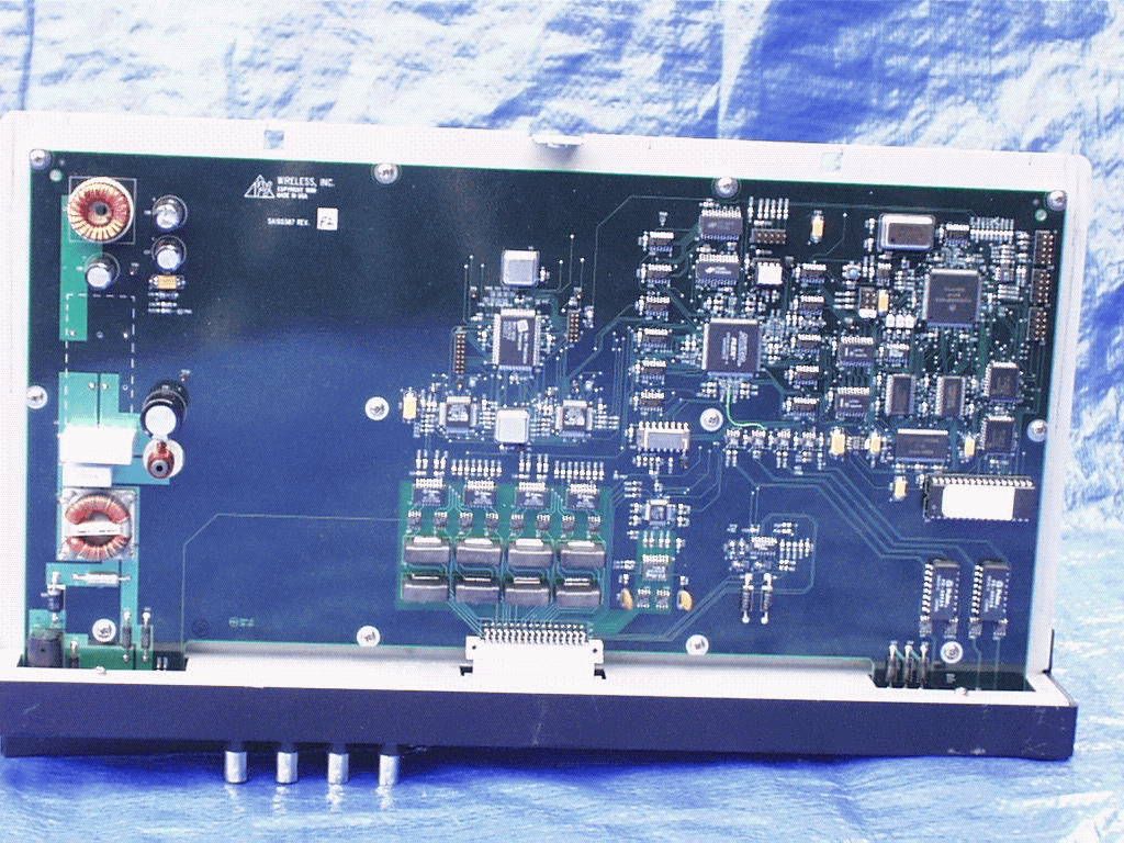
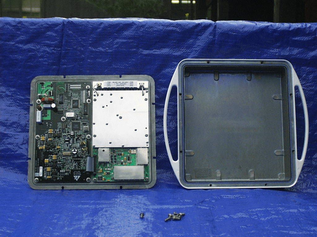
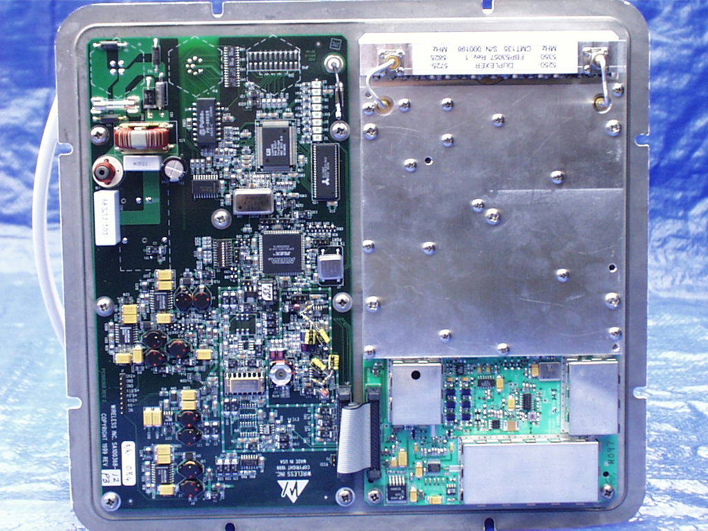
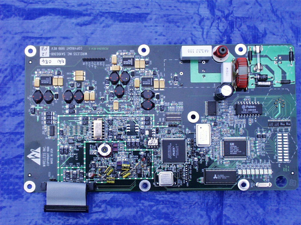
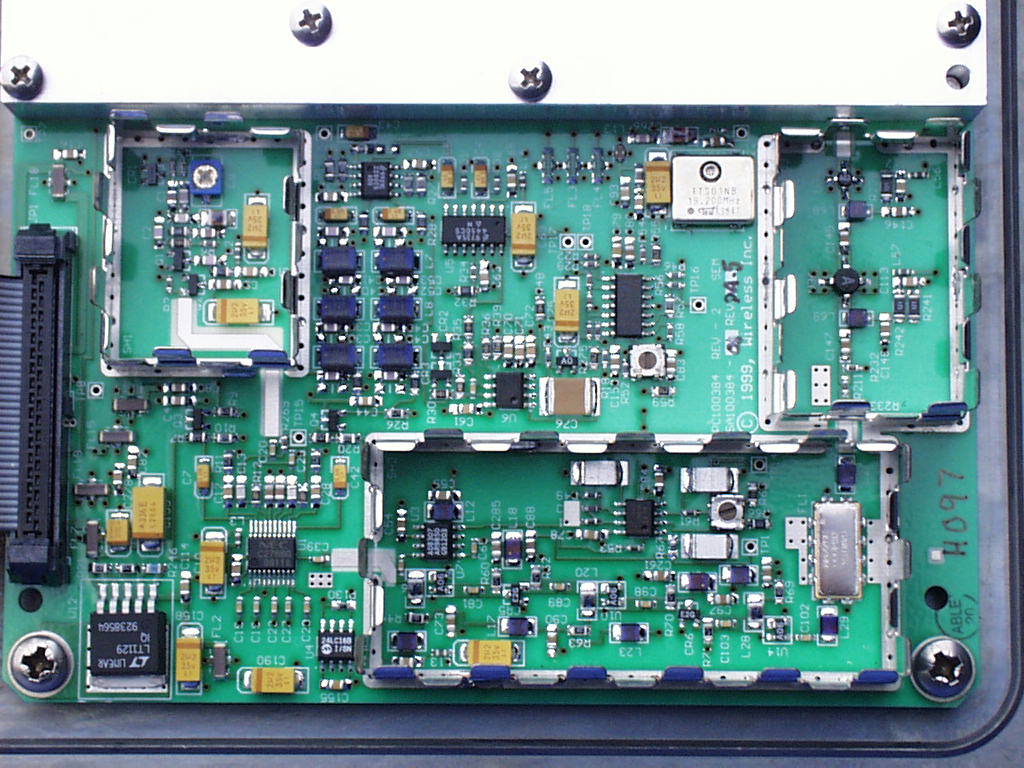
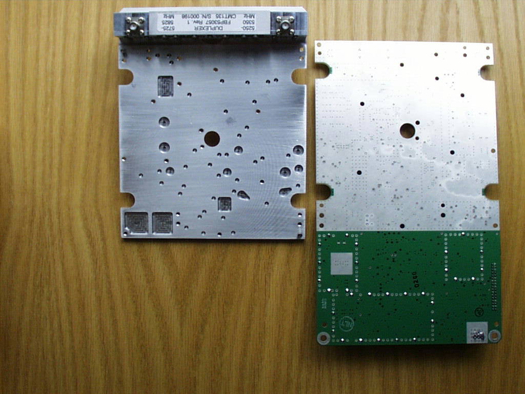
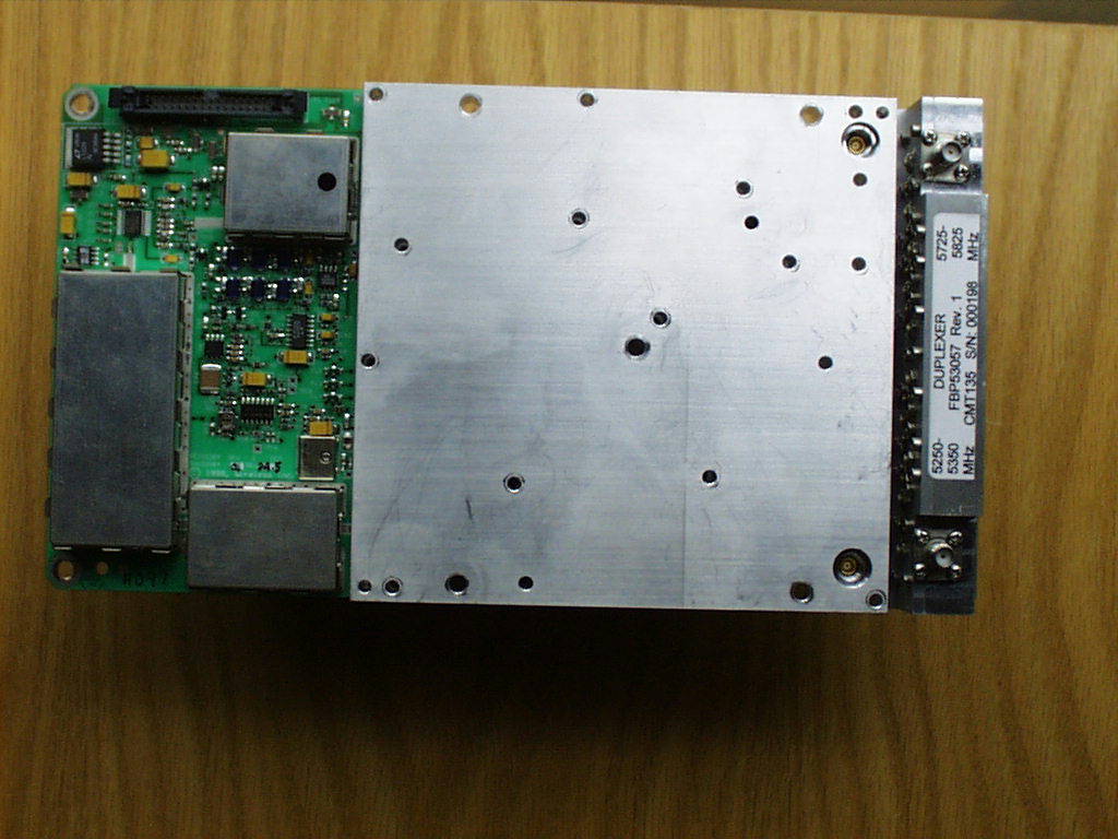
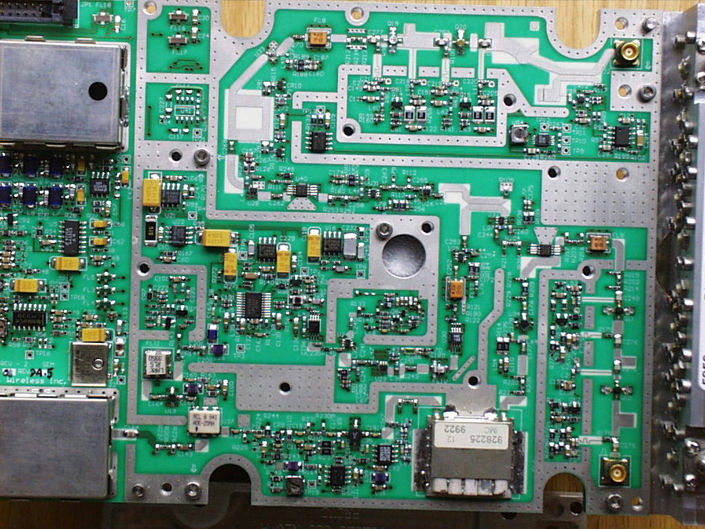
Document Text
Text extracted from the exhibit documents filed with the FCC. Open a document above to read the original.
Users Manual
vii N2-4XE1 Installation and Operation Manual Microwave Antenna Radiation Warning Designed for point-to-point operation,an N2-4XE1 microwave radio system will use directional antennas to transmit and receive microwave signals.These directional antennas are usually circular or rectangular n shape,are generally located outdoors,and are usually mounted on a tower or mast. Referencing OET Bulletin 65 (Edition 97-01,August 1997)from the Federal Communication Commission ’s Office of Engineering &Technology,limits for maximum permissible exposure (MPE)to microwave signals have been adopted by the FCC for both Occupational/Controlled environments and General Population/Uncontrolled environments. These limits are 5.0 mW/ cm2 and 1.0 mW/cm2 respectively. The closer you are to the front center-point of a microwave antenna,the greater the power density of its transmitted microwave signal.Unless you are very close,however,microwave exposure levels will fall far below the MPE limits.To determine how close to a microwave antenna you can be and still re main below the MPE limits noted above,“worst case ”predictions of the field strength and power density levels in the vicinity of an N2-4XE1 ™ microwave antenna can be made from the following calculations.The equation is generally accurate in the far-field of an antenna,and will over-predict power density n the near-field (i.e.close to the antenna). S = P G/4 π R2 where: S =power density (in mW/cm2) P =power input to the antenna (mW) G =power gain of the antenna in the direction of nterest relative to an isotropic radiator R =distance to the center of radiation of the antenna (cm) Note that G,the power gain factor,is usually expressed in logarithmic terms (i.e.,dB),and must be converted using the following equation: G =10 dB/10 In order to satisfy FCC RF ezposure requirements, the antennas used with this product must be installed in such a way as to insure a minum separation distance between the antennas and all persons of the amounts shown in the table below: RF Exposure Safety Information Max RF Power TX Antenna Uncontrolled Environment Controlled MPE 1 mW/cm2 P, dBmG, dBi MPE 1 mW/cm2 MPE 5 mW/cm2 P, dBmG, dBi Safe Distance, cm Safe Distance, cm 12.018.0 20* 20* 12.023.0 20* 20* 12.026.0 22.4 20* 12.028.5 29.9 20* * For fixed and mobile antenna installations, FCC requires a minimum separation distance of 20 cm, regardless of whether calculations would indicate a lesser distance. Wireless,Inc.fully supports the FCC ’s adopted MPE limits,and recommends that personnel maintain appropriate distances from the front of all directional microwave antennas.Should you have questions about N2-4XE1 ™ microwave signal radiation,please contact the Wireless,Inc. Customer Service Department.
Users Manual
2.2.5 Antennas . . Antenna TypeManufacturer and Part Number 2' dish plane polarized, 28.5 dbiGabriel SSP2-52ARI 2' dish dual polarized, 28.5 dBiGabriel SSD2-52ARI *4 ' diameter dish, plane polarized, 33.5 dBiGabriel SSP4-52A *4' diameter dish, dual polarized, 33.5 dBiGabriel SSD4-52A 14" flat panel . 23 dBiMTI Technology MT30102 2 ft dish, 26 dBiRadiowaves SP1-5.2NL 6" ft flat panel, 18 dBiGabiriel DFPD 5-52 • The 4-foot dish antennas are for use outside the USA only, and are not FCC compliant. Maximum Power, dBm, into a ntenna 23 dBi Mti Panel 18 dBi Gabriel panel 26 dBi Radiowaves dish 28.5dBi Gabriel dish fo MHz Max P, dBmMax P, dBmMax P, dBmMax P, dBm 5250- 5350 480not used 5807.3 4**12 4** 0** 5733.612121212 all others 12121212 ** limited by EIRP restrictions in 15.407(b)2 2.2.6 Diagnostics
Users Manual
2.2.5 Antennas . . Antenna TypeManufacturer and Part Number 2' dish plane polarized, 28.5 dbiGabriel SSP2-52ARI 2' dish dual polarized, 28.5 dBiGabriel SSD2-52ARI *4 ' diameter dish, plane polarized, 33.5 dBiGabriel SSP4-52A *4' diameter dish, dual polarized, 33.5 dBiGabriel SSD4-52A 14" flat panel . 23 dBiMTI Technology MT30102 2 ft dish, 26 dBiRadiowaves SP1-5.2NL 6" ft flat panel, 18 dBiGabiriel DFPD 5-52 • The 4-foot dish antennas are for use outside the USA only, and are not FCC compliant. Maximum Power, dBm, into a ntenna 23 dBi Mti Panel 18 dBi Gabriel panel 26 dBi Radiowaves dish 28.5dBi Gabriel dish fo MHz Max P, dBmMax P, dBmMax P, dBmMax P, dBm 5250- 5350 NOT USED** 0**NOT USED**NOT USED** 5807.3 4**12 4** 0** 5733.6121212 8** all others 121212 8** ** limited by EIRP and PSD restrictions in 15.407(a),(b) of FCC Rules 2.2.6 Diagnostics
Users Manual
N2-4XE1 Installation and Operations Manual Part Number 281-102471-201 February 2000 Wireless, Inc. 5452 Betsy Ross Drive Santa Clara, CA 95054-1101 ii N2-4XE1 nstallation and Operation Manual Notice Information in this document is subject to change without notice. No part of this document may be reproduced or transmitted in any form or by any means, electronic or mechanical, for any purpose, without the express written permission of Wireless, Inc. © Copyright 2000, Wireless, Inc. All rights reserved. N2-4XE1 ™ and ACCESS™ Series are trademarks of Wireless, Inc. iii N2-4XE1 Installation and Operation Manual Table of Contents 1.0 General Overview ................................................................................................................. 1 1.1 N2-Link Series Product Family.................................................................................. 1 1.2 Introduction to the N2-4XE1...................................................................................... 1 1.3 Regulatory Information.............................................................................................. 2 2.0 N2-4XE1 Product Profile....................................................................................................... 3 2.1 General Overview...................................................................................................... 3 2.2 Specifications............................................................................................................ 7 2.3 User Interfaces........................................................................................................ 10 2.4 ODU Performance Monitoring................................................................................. 13 2.5 Theory of Operation ................................................................................................ 13 3.0 Equipment Installation and Commissioning........................................................................ 20 3.1 Installation............................................................................................................... 20 3.2 Install the IDU.......................................................................................................... 21 3.3 Outdoor RF Unit Installation.................................................................................... 22 3.4 Commissioning........................................................................................................ 28 4.0 Maintenance and Troubleshooting...................................................................................... 30 4.1 N2-4XE1 Maintenance............................................................................................ 30 4.2 Identifying and Resolving Receive Signal Strength Issues..................................... 31 4.3 Where to Get Further Assistance............................................................................ 32 4.4 Return Procedure.................................................................................................... 33 Appendix A Grounding Practices and Lightning Protection Information.......................................A-1 Appendix B Installation Instructions..............................................................................................B-1 Appendix C Adjustable Panel Antenna Mount..............................................................................C-1 iv N2-4XE1 Installation and Operation Manual Figures Figure 2.1 Typical Deployment of a N2-4XE1 in a Point-to-Point Configuration........................5-6 Figure 2.2 N2-4XE1 Link IDU......................................................................................................10 Figure 2.2a Outdoor Unit, Front View............................................................................................12 Figure 2.2b Outdoor Unit, Back View............................................................................................ 12 Figure 2.3 Block Diagram, IDU....................................................................................................14 Figure 2.4 N2-4XE1 Block Diagram.......................................................................................18-19 Figure 3.1 N2-4XE1 Link Rack Mount......................................................................................... 21 Figure 3.2 Outdoor Unit Mounting Hardware .............................................................................. 22 Figure 3.3 Mounting the Outdoor RF Unit to the Bracket............................................................ 23 Figure 3.3a Mounting the Bracket Latch and Stand Mount Detail................................................. 24 Figure 3.3b Locking the Mounting Hardware ................................................................................ 25 Figure 3.3c N-Type Antenna and Siamesed Ethernet/Power Connections.................................. 26 Figure 3.3d Ground Connection....................................................................................................27 Figure B.1 Two Foot Diameter Antenna.....................................................................................B-1 Figure B.2 Mount Configuration..................................................................................................B-3 Figure B.3 Mounting Hardware Packed......................................................................................B-5 Figure B.4 Mounting Hardware Unpacked..................................................................................B-5 Figure B.5 Parabolic Reflector....................................................................................................B-8 Figure B.6 Unpacking the Radome.............................................................................................B-8 Figure B.7 Antenna Mount Assembly........................................................................................…
Text truncated - open the document above for the full version.
Block Diagram
WL272904 Antenna AGC Test Point Antenna Figure 2.1 - Typical Deployment of a N2-4XE1 Link in a Point-to-Point Configuration 1 Meter ODU-Antenna Interconnect Cable N2-4XE1 Outdoor Unit (as viewed from rear) Catagory 3 Data/Power Cable AGC Test Point 1 Meter ODU-Antenna Interconnect Cable N2-4XE1 Outdoor Unit (as viewed from rear) Catagory 3 Data/Power Cable Status Alarms 12 34 Digital Input Digital Output DC AC 21-56V 250V3A Link Rx Tx NMS Port AUX Port 1 AUX Port 2 + - Data ODU Interface + - Status Alarms 12 34 Digital Input Digital Output DC AC 21-56V 250V3A Link Rx Tx NMS Port AUX Port 1 AUX Port 2 + - Data ODU Interface + - Data 21-56 VDC Data 21-56 VDC N2-4XE1 Indoor Unit N2-4XE1 Indoor Unit N2 - Link TM N2 - Link TM 4 x E1 Input / Outputs 4 x E1 Input / Outputs 8.192 Mbit/sec,4.096 MHz 5.775 GHz +/- 50MHz Baseband Filter Modulator Switchable Attenuation Variable Attenuation Power Amp ALC Circuitry Power Control Circuitry Frequency Doubler Prescaler 2.887 GHz +/- 25MHz VCO Loop Filter Dual Frequency Synthesizer Loop Filter 404.88 MHz VCO FPGA Power Programming and Frequency Programming Carrier Recovery Circuitry 70 MHz VCO AGC Control Circuitry Baseband Filters Quad Demod. Chip Variable Attenuator Variable AttenuatorVariable Attenuator 8.192 Mbit/sec, 4.096 MHz70 MHz474.88 MHz5.300 GHz +/- 50 MHz Preamp Duplexer External Antenna Transmit Chain Frequency Synthesis Receive Chain WL272902 Tx Data From IDU Rx Data To IDU Figure 2.4 - N2-4XE1 Block Diagram
Cover Letter(s)
Thomas N. Cokenias EMC &Radio Approvals Test & Consulting Services for Commercial, Military, International Compliance P.O. Box 1086 El Granada, CA 94018 4 March 2000 FCC Laboratory 7435 Oakland Mills Road Columbia, MD 21046 Attention: Application Examiner Reviewing Engineer Re: Request for confidentiality per Section 0.459 of FCC Rules Applicant: Wireless Inc. FCC ID: EV9-4XE1-5G3 To whom it may concern, Request is hereby submitted, on behalf of my client Wireless Inc., to withhold from public review certain portions of the application for equipment certification for the referenced FCC identifier. In particular, the following sections of the application and report are requested to be kept confidential: Schematics Rationale for request for confidentiality: Wireless Inc. has invested considerable time and materials in research and development to produce the referenced product. Disclosure of the confidential portions of this application to competitors would give them competitive advantage in developing similar products. The $135 fee for confidentiality has been submitted along with the fee for certification. If you have questions or need further information, please contact the undersigned. Sincerely, THOMAS N. COKENIAS EMC Consultant/Agent for Utilicom Inc. Tel 650 726 1263 fax 650 726 [email protected]
ID Label/Location Info
FCC ID Label Format and Location: FCC ID: EV9N2-4XE1-5G3 This device complies with Part 15 of the FCC Rules. Operation is subject to the following two conditions: (1) this device may not cause harmful interference, and (2) this device must accept any interference received, including interference that may cause undesired operation.
RF Exposure Info
To:Thomas Cokenias, T.N. Cokenias Consulting From:Joe Dichoso [email protected] FCC Application Processing Branch Re:FCC ID EV9N2-4XE1-5G3 Applicant:Wireless Inc Correspondence Reference Number: 13451 731 Confirmation Number:EA96901 Date of Original E-Mail:04/13/2000 Place your reply in the RF exposure info folder. Send a separate correspondence letter from any previous request. This is a 5.25-5.35 GHz UNII tx, 15.8 mW listed. Still waiting on the user's manual. Re RF Exposure, please ask the following: 1. The antenna gain list in Exhibit 6 does not match that in the manual submitted for EA 96902 (assuming the same manual is used for both products). Please address. ANS1: New pages have been added to the manual used for these products. A new page vii has the correct wording for RF safety, along with a table of MPE distances vs antenna used. The new page 8 has a revised antenna list to include all those that were tested. The list in the manual includes antennas not tested - the 34 dBi antenna for export only, and a dual polarized dish with the same gain as the single polarized dish that was tested. 2. Please be sure the language in the manual complies with the requests made in reference to EA 96902. ANS2: Refer to revised page vii submitted as separate attachment
RF Exposure Info
vii N2-4XE1 Installation and Operation Manual Microwave Antenna Radiation Warning Designed for point-to-point operation,an N2-4XE1 microwave radio system will use directional antennas to transmit and receive microwave signals.These directional antennas are usually circular or rectangular n shape,are generally located outdoors,and are usually mounted on a tower or mast. Referencing OET Bulletin 65 (Edition 97-01,August 1997)from the Federal Communication Commission ’s Office of Engineering &Technology,limits for maximum permissible exposure (MPE)to microwave signals have been adopted by the FCC for both Occupational/Controlled environments and General Population/Uncontrolled environments. These limits are 5.0 mW/ cm2 and 1.0 mW/cm2 respectively. The closer you are to the front center-point of a microwave antenna,the greater the power density of its transmitted microwave signal.Unless you are very close,however,microwave exposure levels will fall far below the MPE limits.To determine how close to a microwave antenna you can be and still re main below the MPE limits noted above,“worst case ”predictions of the field strength and power density levels in the vicinity of an N2-4XE1 ™ microwave antenna can be made from the following calculations.The equation is generally accurate in the far-field of an antenna,and will over-predict power density n the near-field (i.e.close to the antenna). S = P G/4 π R2 where: S =power density (in mW/cm2) P =power input to the antenna (mW) G =power gain of the antenna in the direction of nterest relative to an isotropic radiator R =distance to the center of radiation of the antenna (cm) Note that G,the power gain factor,is usually expressed in logarithmic terms (i.e.,dB),and must be converted using the following equation: G =10 dB/10 In order to satisfy FCC RF ezposure requirements, the antennas used with this product must be installed in such a way as to insure a minum separation distance between the antennas and all persons of the amounts shown in the table below: RF Exposure Safety Information Max RF Power TX Antenna Uncontrolled Environment Controlled MPE 1 mW/cm2 P, dBmG, dBi MPE 1 mW/cm2 MPE 5 mW/cm2 P, dBmG, dBi Safe Distance, cm Safe Distance, cm 12.018.0 20* 20* 12.023.0 20* 20* 12.026.0 22.4 20* 12.028.5 29.9 20* * For fixed and mobile antenna installations, FCC requires a minimum separation distance of 20 cm, regardless of whether calculations would indicate a lesser distance. Wireless,Inc.fully supports the FCC ’s adopted MPE limits,and recommends that personnel maintain appropriate distances from the front of all directional microwave antennas.Should you have questions about N2-4XE1 ™ microwave signal radiation,please contact the Wireless,Inc. Customer Service Department.
RF Exposure Info
2.2.5 Antennas . . Antenna TypeManufacturer and Part Number 2' dish plane polarized, 28.5 dbiGabriel SSP2-52ARI 2' dish dual polarized, 28.5 dBiGabriel SSD2-52ARI *4 ' diameter dish, plane polarized, 33.5 dBiGabriel SSP4-52A *4' diameter dish, dual polarized, 33.5 dBiGabriel SSD4-52A 14" flat panel . 23 dBiMTI Technology MT30102 2 ft dish, 26 dBiRadiowaves SP1-5.2NL 6" ft flat panel, 18 dBiGabiriel DFPD 5-52 • The 4-foot dish antennas are for use outside the USA only, and are not FCC compliant. Maximum Power, dBm, into a ntenna 23 dBi Mti Panel 18 dBi Gabriel panel 26 dBi Radiowaves dish 28.5dBi Gabriel dish fo MHz Max P, dBmMax P, dBmMax P, dBmMax P, dBm 5250- 5350 480not used 5807.3 4**12 4** 0** 5733.612121212 all others 12121212 ** limited by EIRP restrictions in 15.407(b)2 2.2.6 Diagnostics
RF Exposure Info
vii N2-4XE1 Installation and Operation Manual Microwave Antenna Radiation Warning Designed for point-to-point operation,an N2-4XE1 microwave radio system will use directional antennas to transmit and receive microwave signals.These directional antennas are usually circular or rectangular n shape,are generally located outdoors,and are usually mounted on a tower or mast. Referencing OET Bulletin 65 (Edition 97-01,August 1997)from the Federal Communication Commission ’s Office of Engineering &Technology,limits for maximum permissible exposure (MPE)to microwave signals have been adopted by the FCC for both Occupational/Controlled environments and General Population/Uncontrolled environments. These limits are 5.0 mW/ cm2 and 1.0 mW/cm2 respectively. The closer you are to the front center-point of a microwave antenna,the greater the power density of its transmitted microwave signal.Unless you are very close,however,microwave exposure levels will fall far below the MPE limits.To determine how close to a microwave antenna you can be and still re main below the MPE limits noted above,“worst case ”predictions of the field strength and power density levels in the vicinity of an N2-4XE1 ™ microwave antenna can be made from the following calculations.The equation is generally accurate in the far-field of an antenna,and will over-predict power density n the near-field (i.e.close to the antenna). S = P G/4 π R2 where: S =power density (in mW/cm2) P =power input to the antenna (mW) G =power gain of the antenna in the direction of nterest relative to an isotropic radiator R =distance to the center of radiation of the antenna (cm) Note that G,the power gain factor,is usually expressed in logarithmic terms (i.e.,dB),and must be converted using the following equation: G =10 dB/10 In order to comply with FCC RF Exposure requirements for fixed and mobile operations, the antenna must be installed such that the minimum separation distance, as shown for each antenna, is always maintained between the antenna and all persons. RF Exposure Safety Information Max RF Power TX Antenna Uncontrolled Environment Controlled MPE 1 mW/cm2 P, dBmG, dBi MPE 1 mW/cm2 MPE 5 mW/cm2 P, dBmG, dBi Safe Distance, cm Safe Distance, cm 12.018.0 20* 20* 12.023.0 20* 20* 12.026.0 22.4 20* 12.028.5 29.9 20* • For fixed and mobile antenna installations, FCC requires a minimum separation distance of 20 cm, regardless of whether calculations would indicate a lesser distance. In order to comply with FCC RF Exposure requirements for fixed and mobile operations, the antenna must be installed such that the minimum separation distance, as shown for each antenna, is always maintained between the antenna and all persons. Wireless,Inc.fully supports the FCC ’s adopted MPE limits,and recommends that personnel maintain appropriate distances from the front of all directional microwave antennas.Should you have questions about N2-4XE1 ™ microwave signal radiation,please contact the Wireless,Inc. Customer Service Department.
Test Report
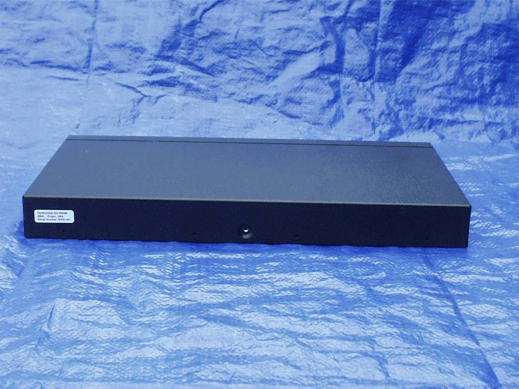
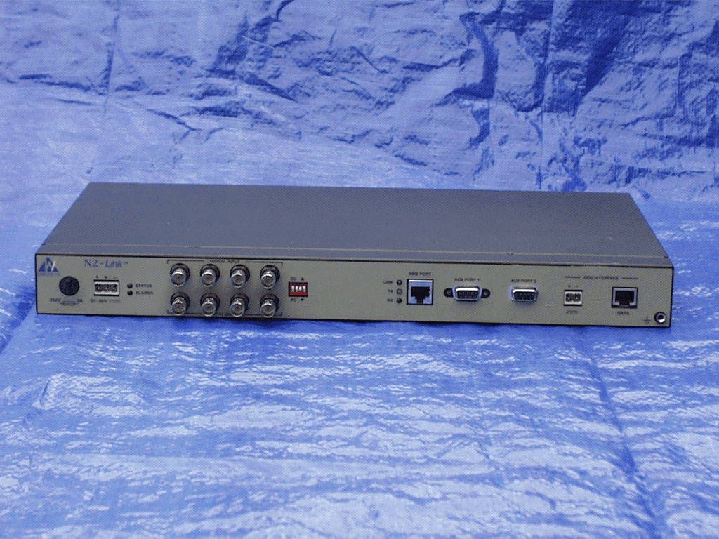
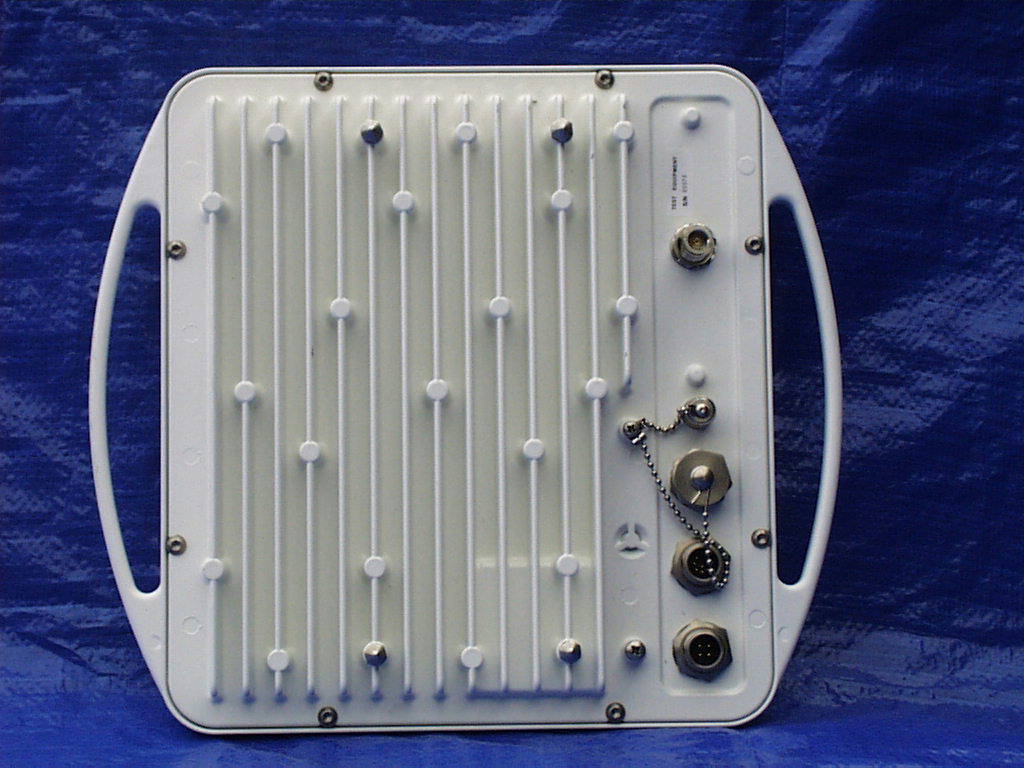
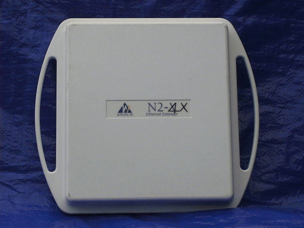
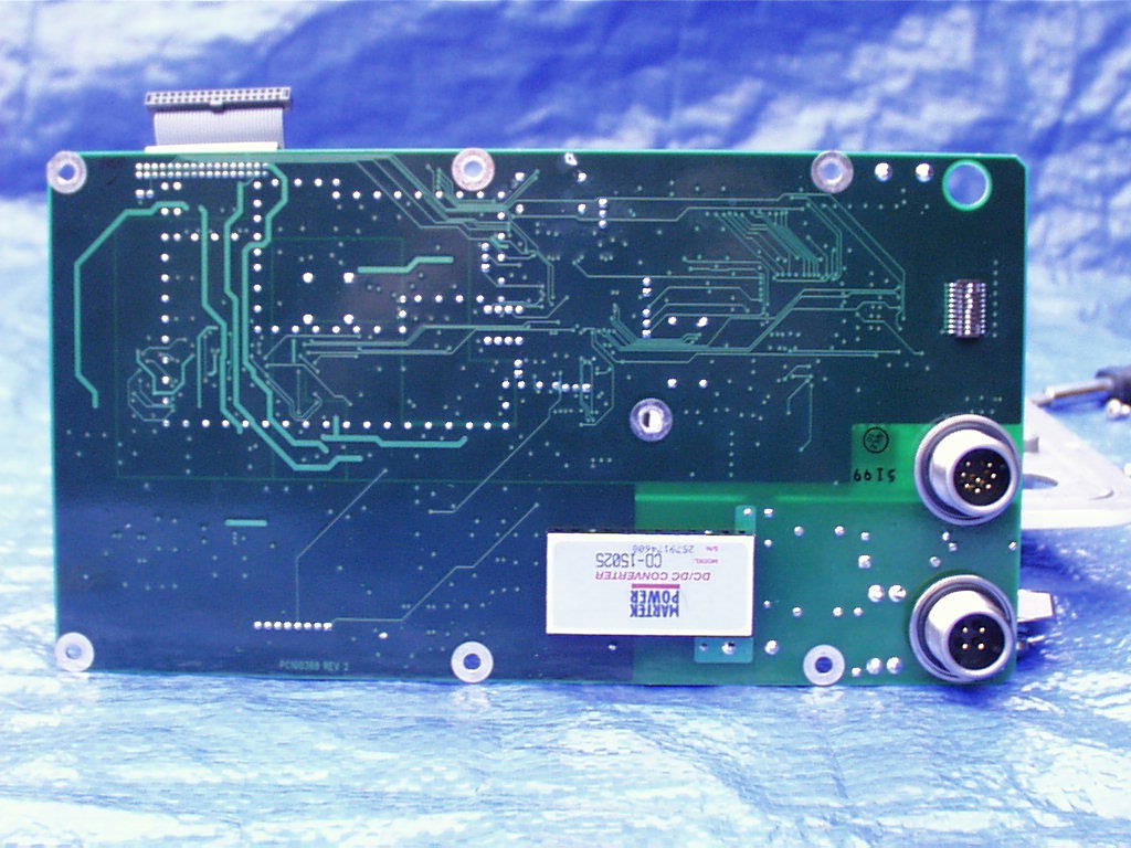
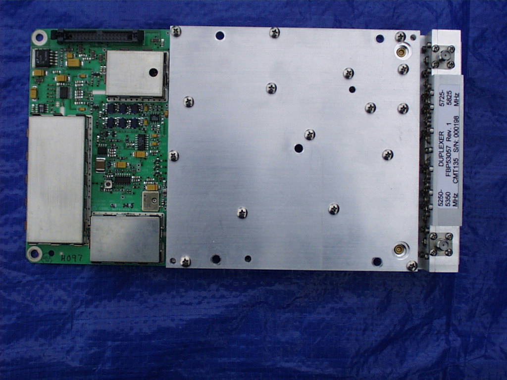
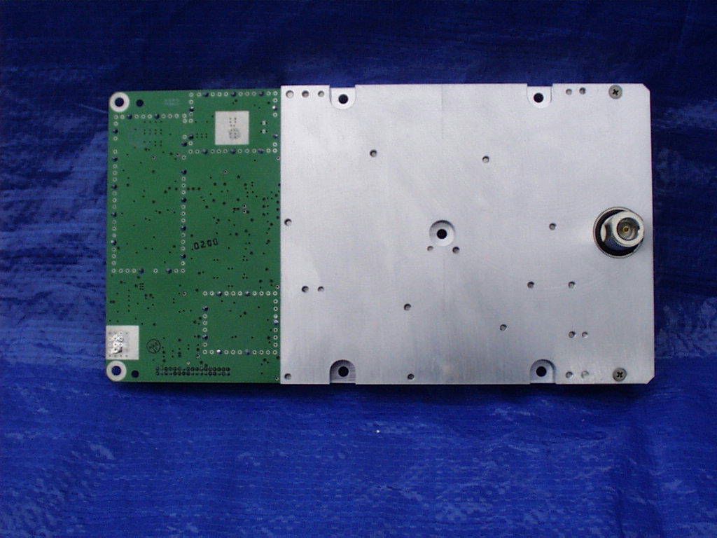
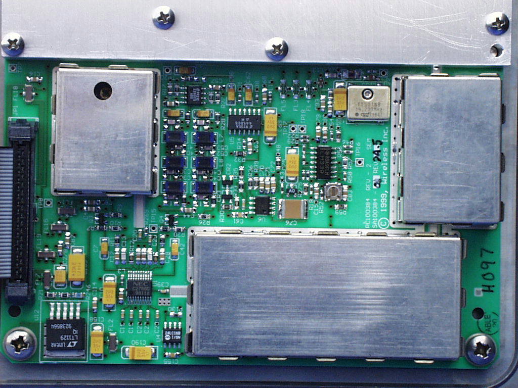
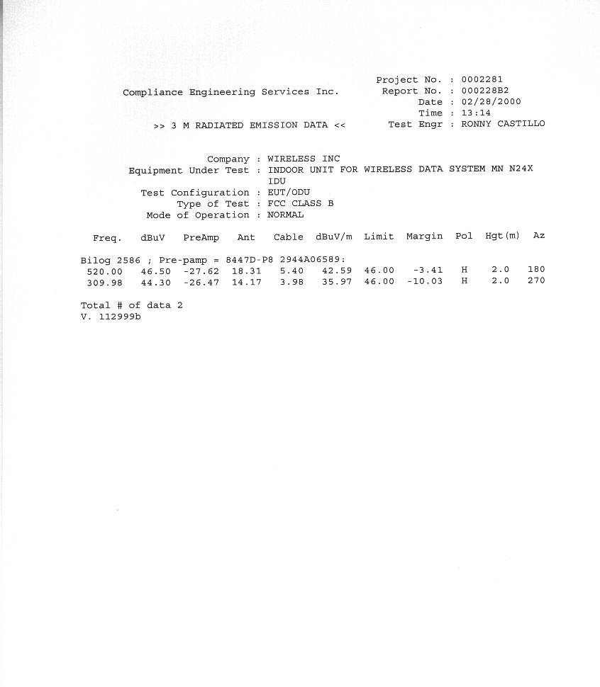
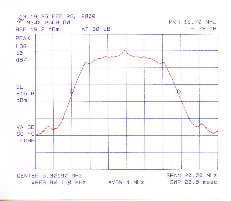
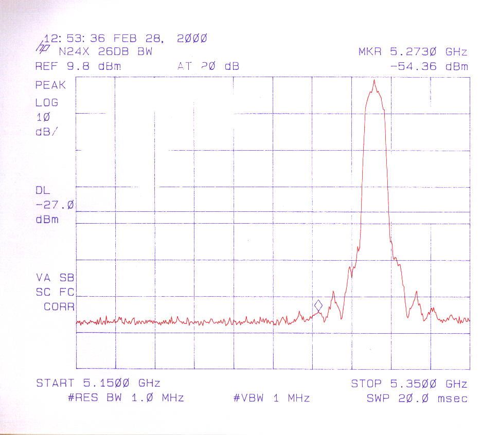
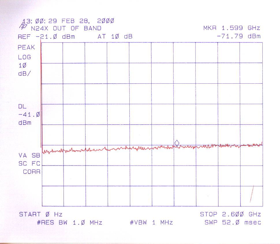
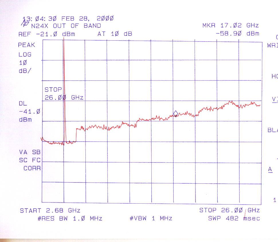
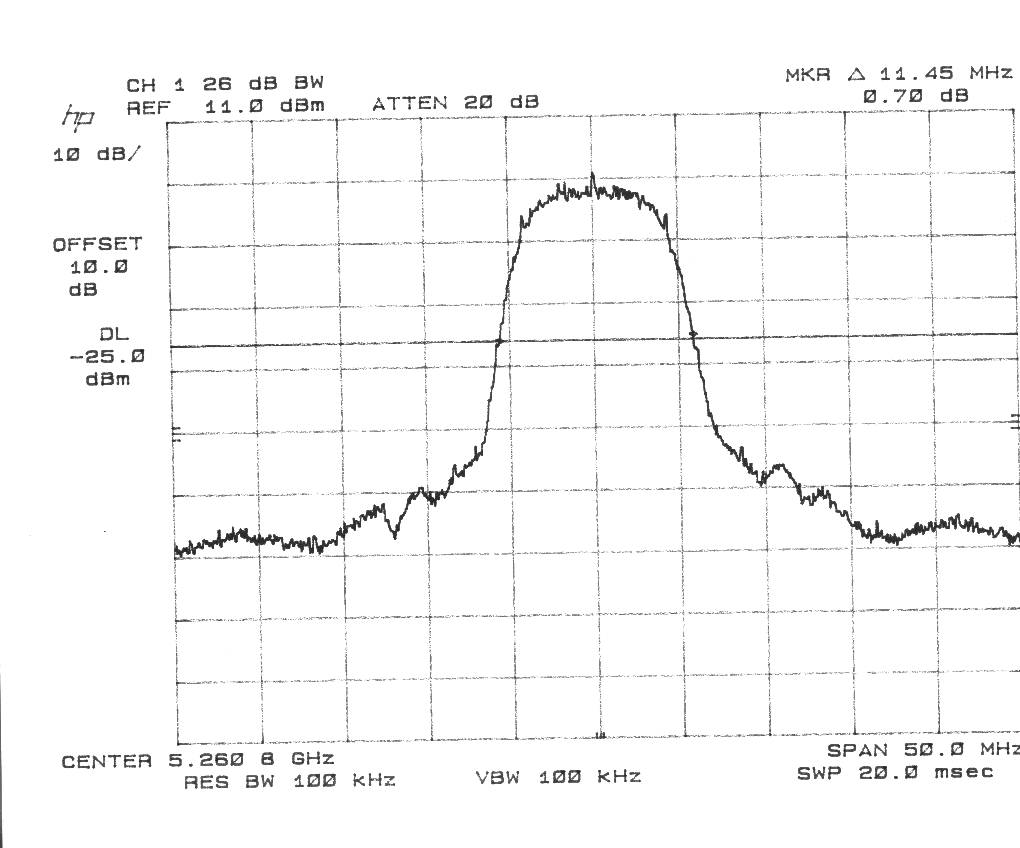
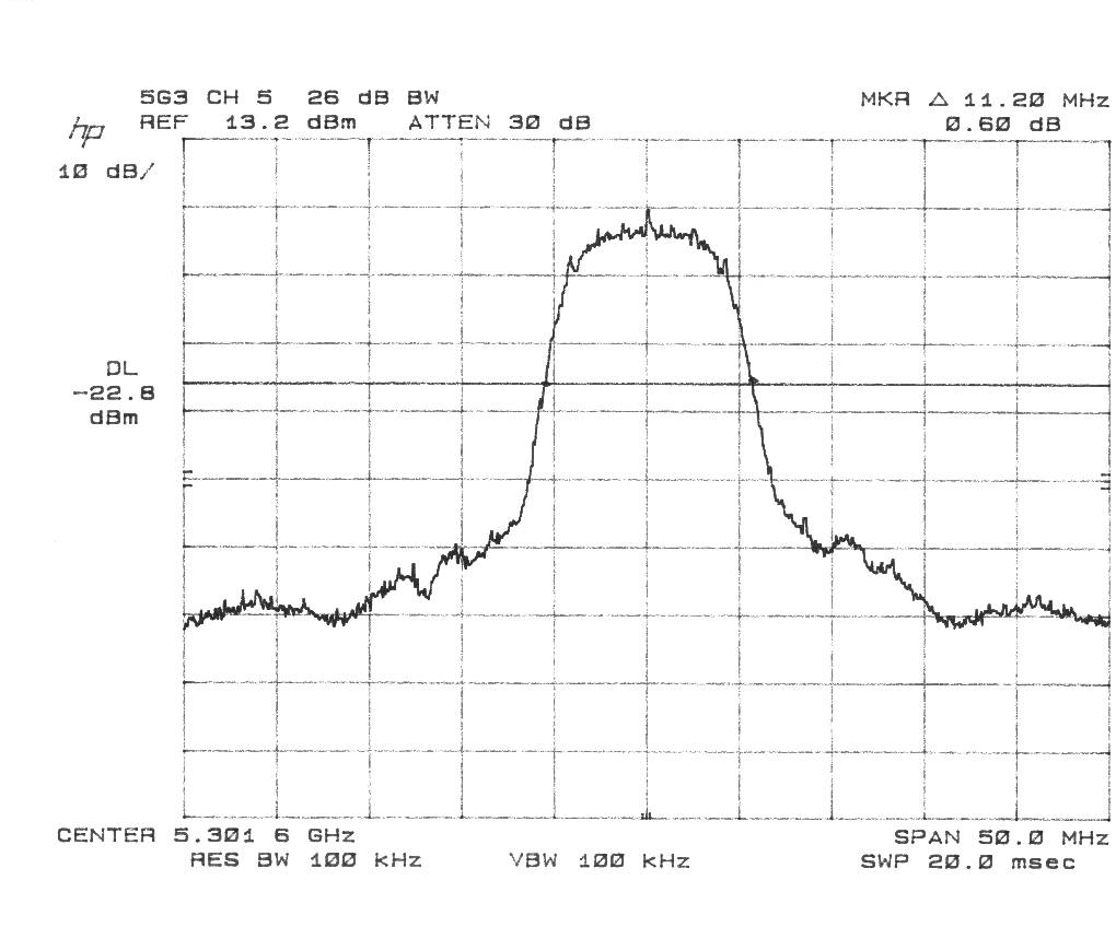
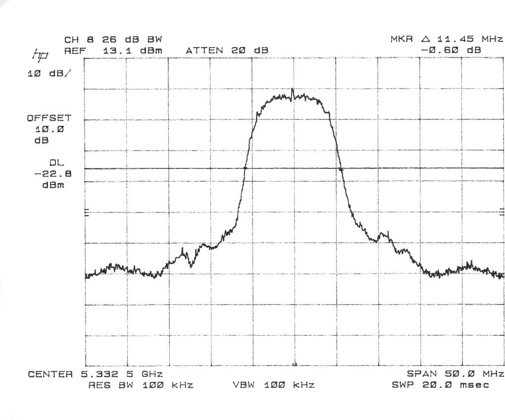
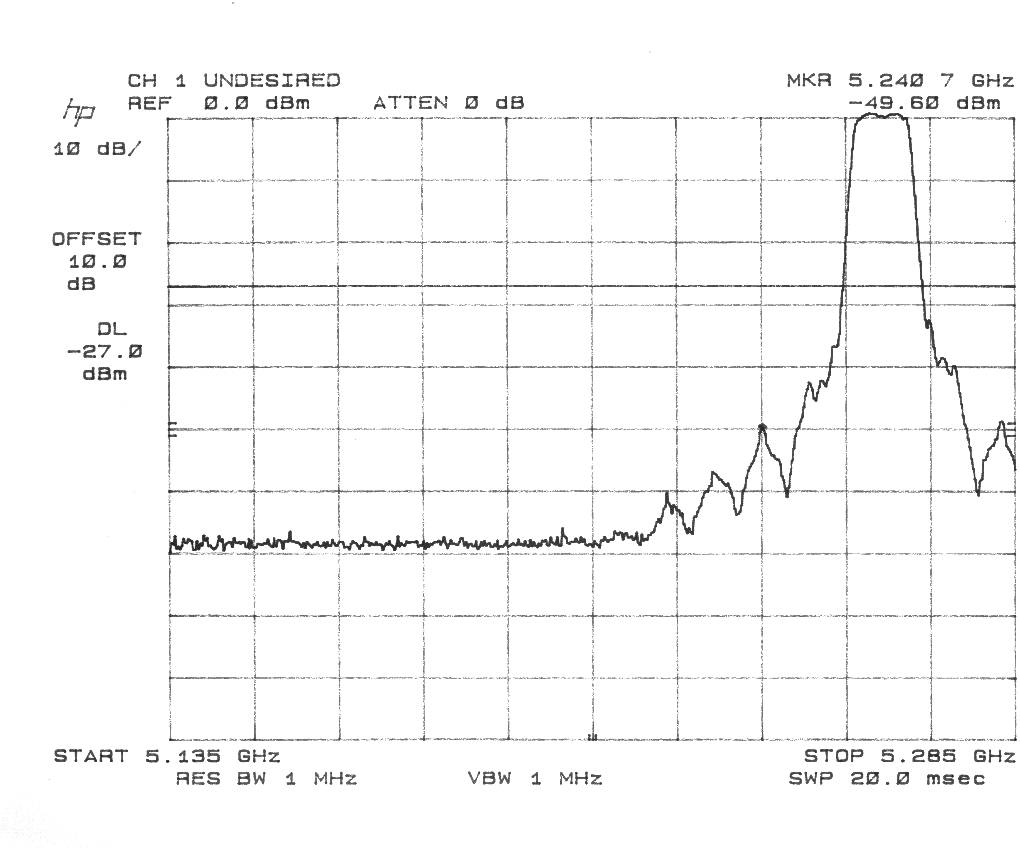
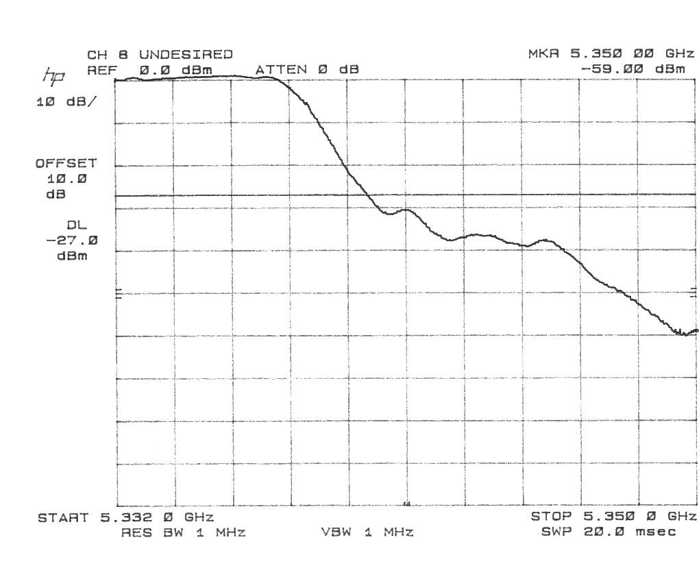
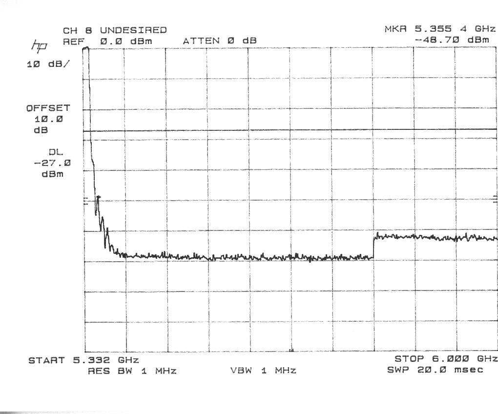
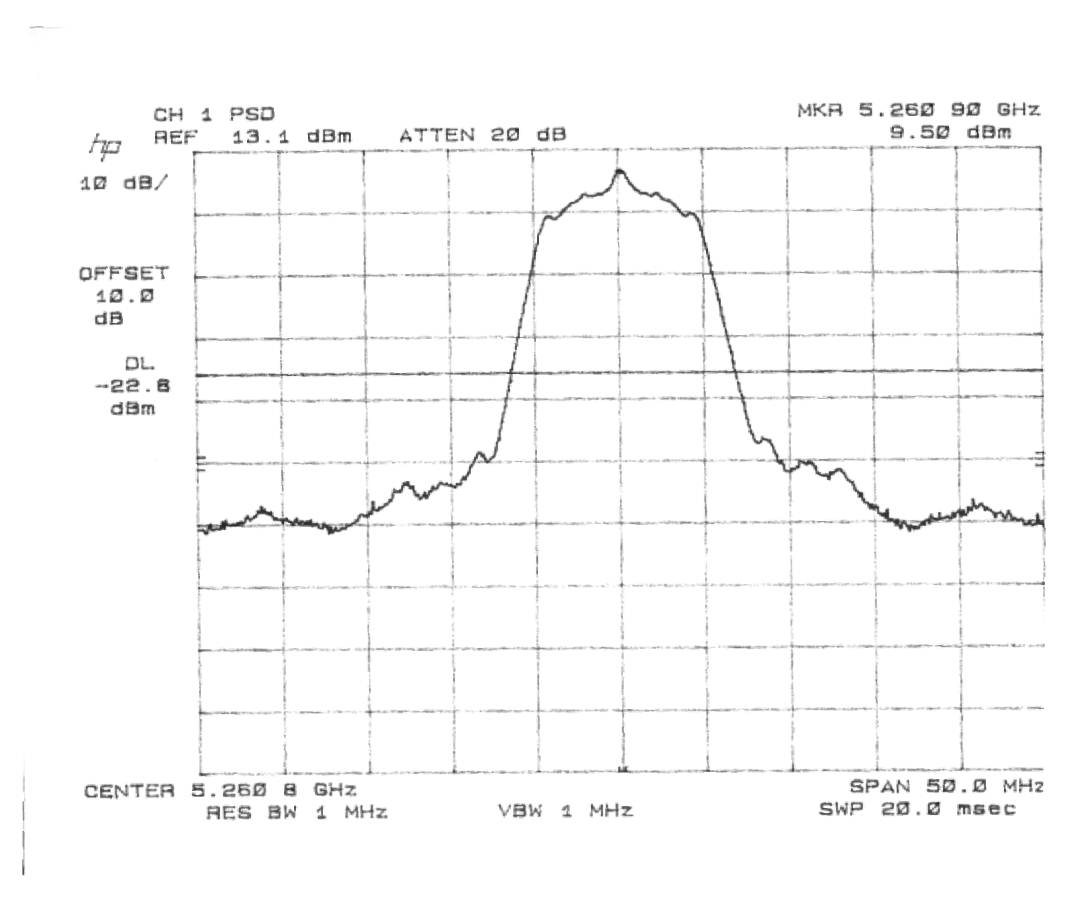
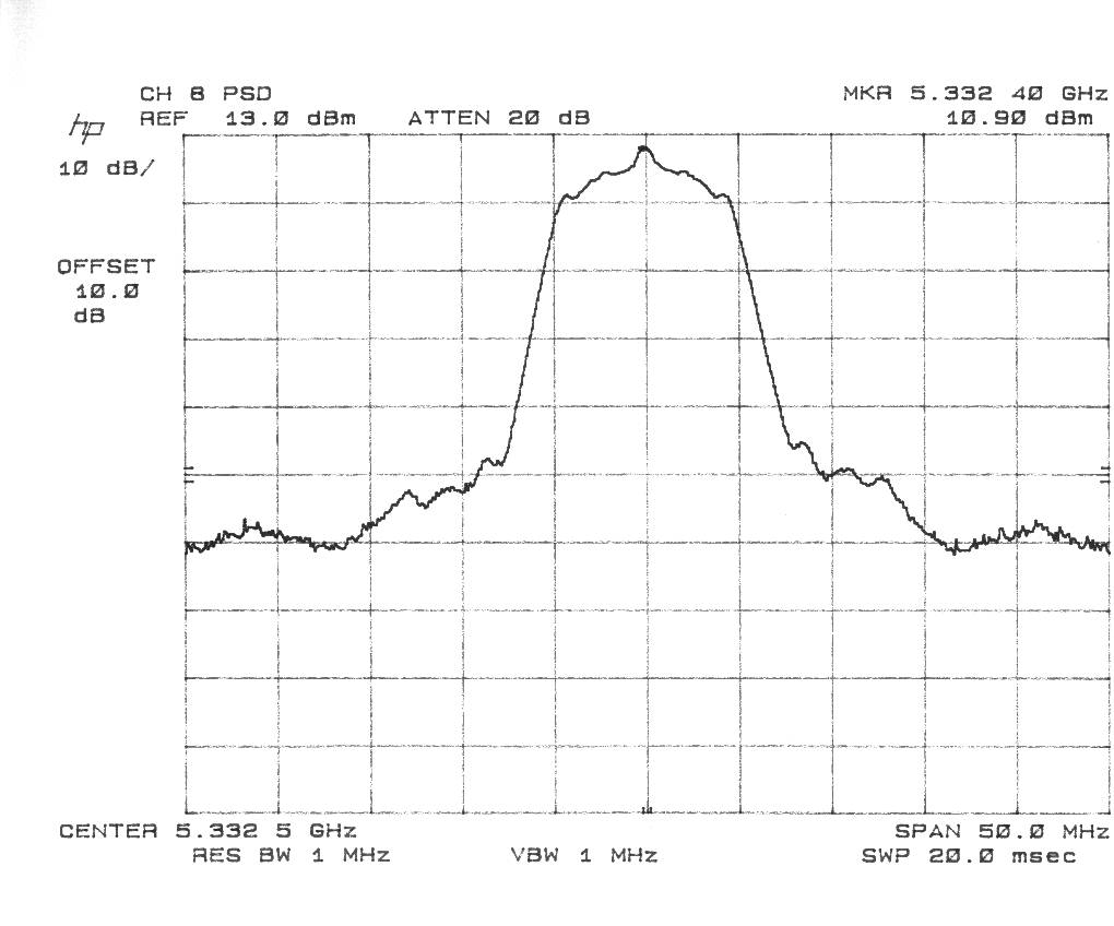
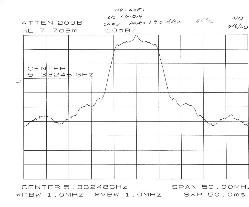
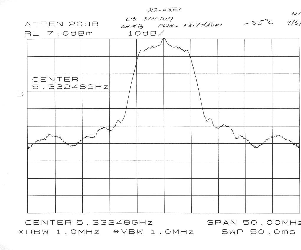
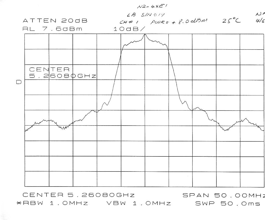
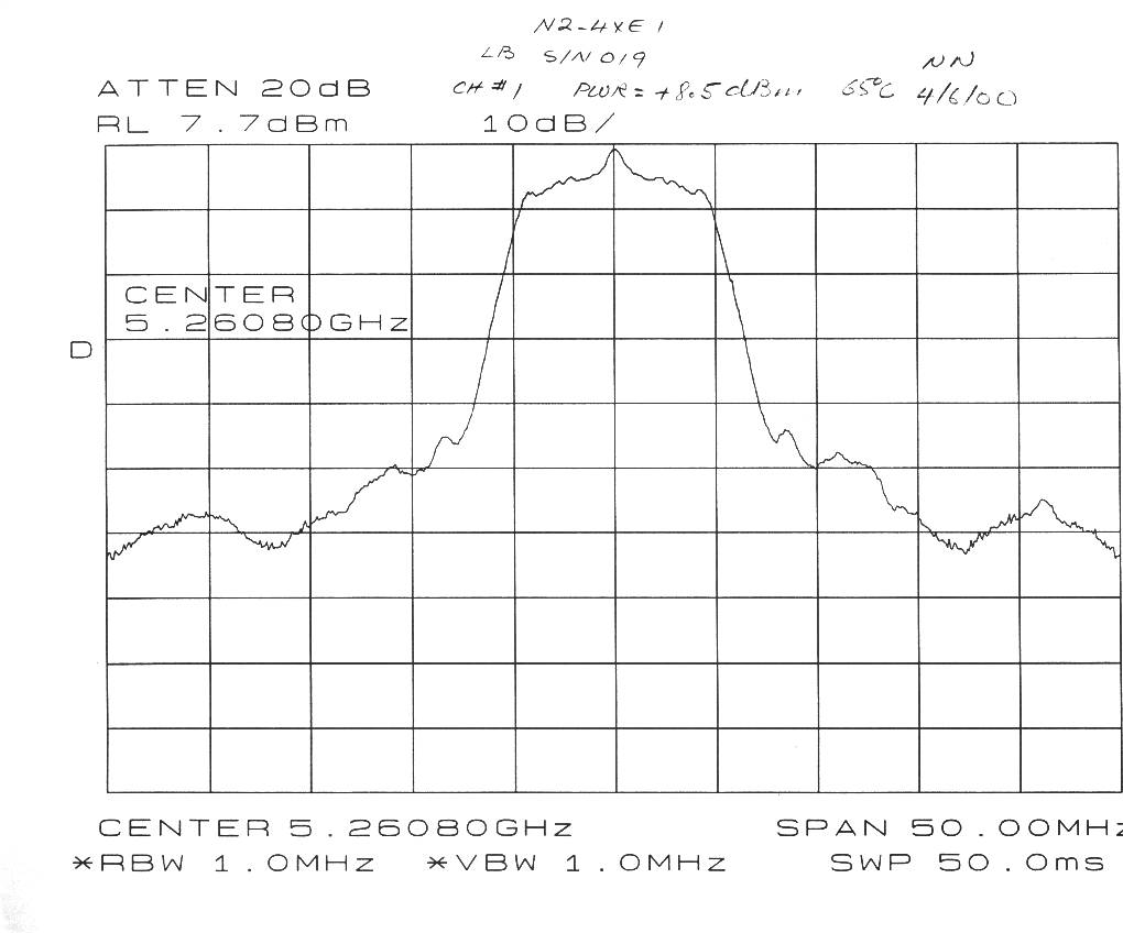
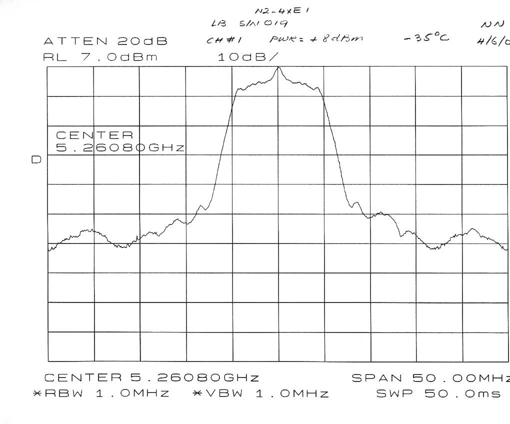
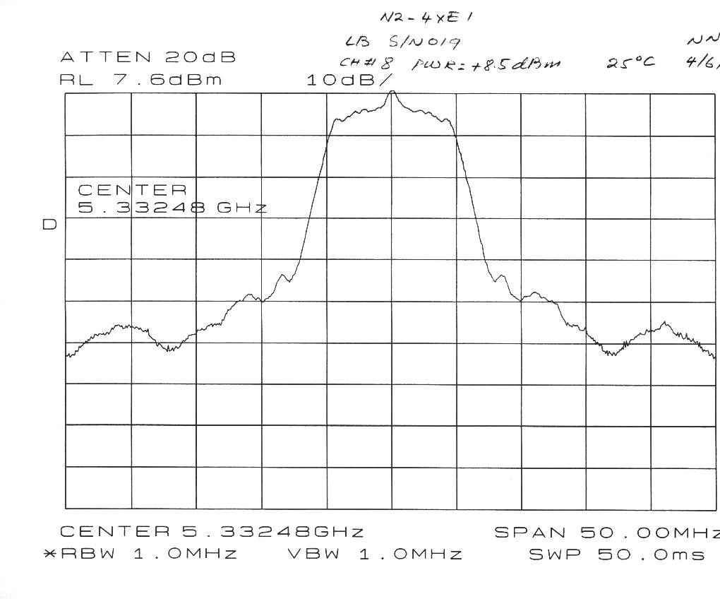
Wireless Inc.FCC ID: EV9N2-4XE1-5G3 1 of 31 EXHIBITS EXHIBIT 1:Letter Requesting Confidentiality under Sec. 0.457(d) EXHIBIT 2: Product Description and Operation Overview EXHIBIT 3:Information for which Confidentiality is Requested Schematics EXHIBIT 4:Product Photographs EXHIBIT 5:User Manual and FCC ID Label EXHIBIT 6:RF Hazard Information per Sec. 1.1307 EXHIBIT 7: Report of Measurements Wireless Inc.FCC ID: EV9N2-4XE1-5G3 2 of 31 EXHIBIT 1:Letter Requesting Confidentiality under Sec. 0.457(d) - refer to separate Word attachment Wireless Inc.FCC ID: EV9N2-4XE1-5G3 3 of 31 EXHIBIT 2:Product Description and Operation Overview General Overview The N2-4XE1 is a point to point Wireless Extension operating in the 5.3/5.7 GHz UNII band as authorized in rule sections 15.401 through 15.407.The unit is enclosed in a weather proof outdoor enclosure and is intended to provide data links over distances up to 10 km.The radio in the unit operates full duplex, transmitting and receiving data at the rate of 8.448 Mbps. The radio is modulated using BPSK. The product uses two separate 100 MHz bands within the U-NII frequency spectrum. Within these bands,the N2-4XE1 series operates in one of many independent channels providing for frequency reuse and network flexibility. Synthesized RF channel selection is field configurable,as are the power output options for the selection of antenna sizes.. Frequency Band: Full-duplex operation in the UNII band Frequency Range:5,250 -5,350 MHz and 5,725 -5,825 MHz Digital Interface Capacity Options:4xE1 IT U-T /E1 Type:Based on 4 E-1 inputs Line rate:4 x 2.048 Mb/s Line Code:HDB3 Interface:75 unbalanced or optional 120 unbalanced Connectors:BNC (75 )or RJ-48C (120 ) 5.3 GHz TX( Low Band) 5.7 GHz RX (High Band) Frequency Range:5,250 -5,350 MHz 5,725 -5,825 MHz Output power:0 dBm 0 dBm +4 dBm +4 dBm +8 dBm +8 dBm +12 dBm +12 dBm A description of the theory of operation and product configuration is found in an attachment to this application and report. Wireless Inc.FCC ID: EV9N2-4XE1-5G3 4 of 31 System Interconnection - refer to attachment fccbloc.pdf Wireless Inc.FCC ID: EV9N2-4XE1-5G3 5 of 31 EXHIBIT 3:Information for which Confidentiality is Requested Schematics Wireless Inc.FCC ID: EV9N2-4XE1-5G3 6 of 31 EXHIBIT 4: Product Photographs -refer to separate jpg attachments Wireless Inc.FCC ID: EV9N2-4XE1-5G3 7 of 31 EXHIBIT 5:User Manual and FCC ID Label -refer to separate .pdf attachment Wireless Inc.FCC ID: EV9N2-4XE1-5G3 8 of 31 EXHIBIT 6: RF Hazard Information Per Sec. 1.1307 For transmitters operating in the 5250-5350 MHz frequency range, paragraph 1.1310 limits maximum permissible exposure (MPE) to 1 mW/cm2 for uncontrolled environments. The maximum distance from the antenna at which MPE is met or exceeded is calculated from the equation relating field strength in V/m, transmit power in watts, transmit antenna gain, and separation distance in meters: E,V/m = ( √ (30*P*G))/d Power density, mW/m2 = E 2 /3770 E for MPE 1mW/m2 = 61.4 V/m Simplifying and rearranging terms: d = ( √ (30*P*G))/61.4 Converting to decibels: 20 log d = 10 log 30 + 10 log P watts + G dBi -35.8 dB 20 log d = 14.77 + PdBm - 30 dB -35.8 + GdBi 20 log d = P dBm + G dBi -51 ; d = 10^(PdBm+GdBi-51)/20 EUT 26 dB bandwidth: 11.7 MHz Maximum allowed EUT output power: 11 dBm + 10 log(11.7) = 21.7 dBm Defacto EIRP limit: 21.7 dBm + 6 dBi = 27.7 dBm EIRP MPE for 27.7dBm EIRP = 10^(27.7-51)/20 = 7 cm Instructions will be placed in the user manual instructing installers and users to maintain 20 cm separation distance during operation of the EUT. Wireless Inc.FCC ID: EV9N2-4XE1-5G3 9 of 31 EXHIBIT 7:Report of Measurements Wireless Inc.FCC ID: EV9N2-4XE1-5G3 10 of 31 FCC CERTIFICATION INFORMATION The following information is in accordance with FCC Rules, 47CFR Part 2. 2.1033(b)1Applicant: Wireless Inc. 5452 Betsy Ross Drive Santa Clara CA 95054-1101 2.1033(b)2FCC ID : EV9N2-4XE1-5G3 2.1033(b)3 Installation instructions are found in attached document. 2.1033(b)4 A brief description of the circuit functions is found in attached document 2.1033(b)5 Block diagram is found in attached document 2.1033(b)6 Report of measurements is found below. 2.1033(b)7 Product photographs are attached in JPEG format. 2.1033(b)8 The EUT is operated with accessory devices described below and in the attachments submitted. 2.1033(b) 9 NOT APPLICABLE 2.1033(b)10 - 12 NOT APPLICABLE 15.203 The Wireless UNII radio will be professionally installed. At present, there are four antennas specified for use with the radio: Gabriel SSP2-52ARI 28.5 dBi dish MTI Technology MT 30102 23 dBi flat panel array Radiowaves SP1-5.2NL26 dBi dish Gabriel DFPD.5-52 18 dBi flat panel array Wireless Inc.FCC ID: EV9N2-4XE1-5G3 11 of 31 SUMMARY OF TEST RESULTS 15.407 General Technical Requirements The UNII requirements for maximum power, peak power spectral density, minimum 26 dB emissions bandwidth, and maximum EIRP are interdependent variables. In addition, the level of transmitter spectral re-growth at the UNII band edges will limit the power output that may be transmitted into a particular antenna, since the emission limit is -17dBm/MHz and /or -27dBm/MHz EIRP, dependent on both antenna gain and power input. The Wireless UNII radio has user programmable output power levels from 0 - 12 dBm. The 26 dB channel bandwidth is 11.7 MHz. A number of antennas can be used with the point-to-point UNII radio, with gains that vary between 18.5 dBi and 34 dBi. 15.407(a)3 Power limits 11 dBm + 10 log (11.7) = 21.7 dBm max. for 5.25 - 5.35 GHZ band Peak power spectral density: = 11 dBm/MHz Defacto EIRP limit: 21.7 dBm + 6 dBi = 27.7 dBm EIRP Maximum Power, dBm, into antenna 23 dBi Mti Panel 18 dBi Gabriel panel 26 dBi Radiowaves dish 28.5dBi Gabriel dish fo MHzMax P, dBmMax P, dBmMax P, dBmMax P, dBm 57394 pre-set8 pre-set0 pre-set-1 using ext. atten 5736480-1 5733480-1 Wireless Inc.FCC ID: EV9N2-4XE1-5G3 12 of 31 RF Output Power Measurements Ref: 15.407(a)2 Measure…
Text truncated - open the document above for the full version.
Test Report
Wireless Inc.FCC ID: EV9N2-4XE1-5G3 1 of 31 EXHIBITS EXHIBIT 1:Letter Requesting Confidentiality under Sec. 0.457(d) EXHIBIT 2: Product Description and Operation Overview EXHIBIT 3:Information for which Confidentiality is Requested Schematics EXHIBIT 4:Product Photographs EXHIBIT 5:User Manual and FCC ID Label EXHIBIT 6:RF Hazard Information per Sec. 1.1307 EXHIBIT 7: Report of Measurements Wireless Inc.FCC ID: EV9N2-4XE1-5G3 2 of 31 EXHIBIT 1:Letter Requesting Confidentiality under Sec. 0.457(d) - refer to separate Word attachment Wireless Inc.FCC ID: EV9N2-4XE1-5G3 3 of 31 EXHIBIT 2:Product Description and Operation Overview General Overview The N2-4XE1 is a point to point Wireless Extension operating in the 5.3/5.7 GHz UNII band as authorized in rule sections 15.401 through 15.407.The unit is enclosed in a weather proof outdoor enclosure and is intended to provide data links over distances up to 10 km.The radio in the unit operates full duplex, transmitting and receiving data at the rate of 8.448 Mbps. The radio is modulated using BPSK. The product uses two separate 100 MHz bands within the U-NII frequency spectrum. Within these bands,the N2-4XE1 series operates in one of many independent channels providing for frequency reuse and network flexibility. Synthesized RF channel selection is field configurable,as are the power output options for the selection of antenna sizes.. Frequency Band: Full-duplex operation in the UNII band Frequency Range:5,250 -5,350 MHz and 5,725 -5,825 MHz Digital Interface Capacity Options:4xE1 IT U-T /E1 Type:Based on 4 E-1 inputs Line rate:4 x 2.048 Mb/s Line Code:HDB3 Interface:75 unbalanced or optional 120 unbalanced Connectors:BNC (75 )or RJ-48C (120 ) 5.3 GHz TX( Low Band) 5.7 GHz RX (High Band) Frequency Range:5,250 -5,350 MHz 5,725 -5,825 MHz Output power:0 dBm 0 dBm +4 dBm +4 dBm +8 dBm +8 dBm +12 dBm +12 dBm A description of the theory of operation and product configuration is found in an attachment to this application and report. Wireless Inc.FCC ID: EV9N2-4XE1-5G3 4 of 31 System Interconnection - refer to attachment fccbloc.pdf Wireless Inc.FCC ID: EV9N2-4XE1-5G3 5 of 31 EXHIBIT 3:Information for which Confidentiality is Requested Schematics Wireless Inc.FCC ID: EV9N2-4XE1-5G3 6 of 31 EXHIBIT 4: Product Photographs -refer to separate jpg attachments Wireless Inc.FCC ID: EV9N2-4XE1-5G3 7 of 31 EXHIBIT 5:User Manual and FCC ID Label -refer to separate .pdf attachment Wireless Inc.FCC ID: EV9N2-4XE1-5G3 8 of 31 EXHIBIT 6: RF Hazard Information Per Sec. 1.1307 For transmitters operating in…
Text truncated - open the document above for the full version.
Contact Information
Applicant
Robert A Czerwinski(Director, Compliance/QA)
Technical Contact
T.N. Cokenias ConsultingThomas N Cokenias
[email protected]650 726 1263
355 El Granada Blvd · El Granada, California · United States
Non-Technical Contact
T.N. Cokenias ConsultingThomas N Cokenias
[email protected]650 726 1263
Test Firm
Compliance Certification Services IncSteve Cheng
Technical Specifications
| # | Rule Parts | Frequency Range | Power Output |
|---|---|---|---|
| 1 | 15E | 5.26 GHz - 5.33 GHz | 1.00 mW |
Other Applications from Wireless Inc
EV9N2WLAX-5G7
Jan 17, 2001Link AX ATM25 Extender
Equipment Class
NII - Unlicensed National Information Infrastructure TX
EV9N2WLAX-5G3
Dec 11, 2000UNII WLAN
Equipment Class
NII - Unlicensed National Information Infrastructure TX
EV9N2-4XE1-5G7
May 10, 2000Point to Point Data Transceiver
Equipment Class
NII - Unlicensed National Information Infrastructure TX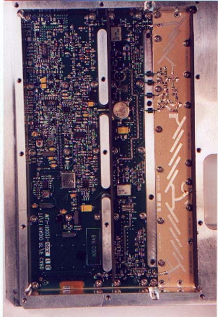
EV9N2X5-7S1-16B
Jan 23, 2000NII - Unlicensed National Information Infrastructure TX
Equipment Class
NII - Unlicensed National Information Infrastructure TX
EV9N2X5-3S1-16B
Jan 23, 2000NII - Unlicensed National Information Infrastructure TX
Equipment Class
NII - Unlicensed National Information Infrastructure TX