EV9N2WLAX-5G7Link AX ATM25 Extender
Wireless Inc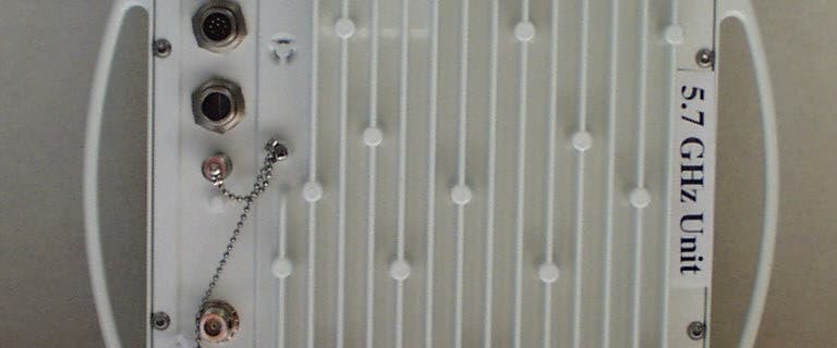
Click to zoom
Application Details
- Equipment Class
- NII - Unlicensed National Information Infrastructure TX
- Date of Grant
- Jan 17, 2001
- Application Purpose
- Original Equipment
- Date of Application
- Jan 17, 2001
- Equipment Note
- Link AX ATM25 Extender
- Frequency Range
- 5735.68000000 - 5807.36000000
- Company
- Wireless Inc
- Country
- United States
Documents & Files
Document Text
Text extracted from the exhibit documents filed with the FCC. Open a document above to read the original.
Users Manual
WaveNet Link AX ATM-25 U-NII Band Digital Radio System Installation and Operations Manual Part Number 100273-001 Version 0.8 October 2000 Wireless Inc. 5452 Betsy Ross Drive Santa Clara, CA. 95054-1101 (408) 727-8383 ii WaveNet Link AX Installation and Operations Manual Notice Information in this document is subject to change without notice. No part of this document may be reproduced or transmitted in any form or by any means, electronic or mechanical, for any purpose, without the express written permission of Wireless, Inc. © Copyright 2000, Wireless, Inc. All rights reserved. Link AX™ and WaveNet Link™ Series are trademarks of Wireless, Inc. iii WaveNet Link AX Installation and Operations Manual Table of Contents 1.0General Overview ................................................................................................................. 1 1.1WaveNet Link Series Product Family ........................................................................ 1 1.2Introduction to the Link AX ........................................................................................ 1 1.3Regulatory Information .............................................................................................. 2 2.0Link AX Product Profile ......................................................................................................... 3 2.1General Overview ...................................................................................................... 3 2.2Specifications ............................................................................................................ 5 2.3User Interfaces .......................................................................................................... 8 2.4ODU Performance Monitoring ................................................................................... 8 2.5Theory of Operation .................................................................................................. 9 3.0Equipment Installation and Commissioning ........................................................................ 15 3.1Installation ............................................................................................................... 15 3.2ATM25 Data Connectors ......................................................................................... 19 3.3Connect the Power Supply ...................................................................................... 19 3.4Outdoor RF Unit Installation .................................................................................... 20 3.5Indoor Unit ............................................................................................................... 27 3.6DIP Switch Function and Configuration .................................................................. 28 3.7Commissioning ........................................................................................................ 30 4.0Antenna Installation ............................................................................................................. 35 4.1Equipment Inventory List ......................................................................................... 35 4.2Antenna Installation and Rough Alignment ............................................................. 36 4.3RF Cable Install and Seal ........................................................................................ 50 5.0Maintenance and Troubleshooting ...................................................................................... 63 5.1Link AX Maintenance .............................................................................................. 63 5.2Where to get Further Assistance ............................................................................. 64 5.3Return Procedure .................................................................................................... 65 Appendix A Grounding Practices and Lightning Protection Information ....................................... A-1 iv WaveNet Link AX Installation and Operations Manual Figures Figure 2.1Typical Deployment of a Link AX in a Point-to-Point Configuration ............................. 4 Figure 2.2a Outdoor Unit, Front View ............................................................................................10 Figure 2.2b Outdoor Unit, Back View ............................................................................................ 10 Figure 2.2c Outdoor Unit, Front View, Integral Antenna ............................................................... 11 Figure 2.2d Outdoor Unit, Back View, Integral Antenna ............................................................... 11 Figure 2.3Link AX Indoor Unit (IDU) ........................................................................................... 13 Figure 2.4Link AX Block Diagram ............................................................................................... 14 Figure 3.1Power Cord Connection ............................................................................................. 19 Figure 3.2Outdoor Unit Mounting Hardware .............................................................................. 20 Figure 3.3Attaching the Pole or Tilt Mount Adaptor Bracket ...................................................... 21 Figure 3.4Mounting the Outdoor RF Unit to the Bracket ............................................................ 22 Figure 3.5a Mounting Bracket Latch and Stud Mount Detail ......................................................... 23 Figure 3.5b Locking the Mounting Hardware ................................................................................ 24 Figure 3.6a N-Type Antenna and Siamesed Ethernet/Power Connections .................................. 25 Figure 3.6b Ground Connection ....................................................................................................26 Figure 3.7Link Ax Indoor Unit (IDU) .....................…
Text truncated - open the document above for the full version.
Users Manual
NOTE: After switch settings are entered, the screw-on cap is permanently attached using LOK TITE adhesive, to deny user access to the settings.
Attestation Statements
TCB RF Exposure Review Procedure Statement FCC ID:EV9N2WLAX-5G7 Transmitter Category Device Type Product Category Approval and Review Procedures Used Specific Procedures: V Part 15 Fixed and Mobile Transmitter UNII (b) Section K SP(2), SP(3), SP(7), SP(8) and SP(9) • Grant Condition : This device requires professional installation. The antenna(s) used for this transmitter must be fixed-mounted on outdoor permanent structures with a separation distance of at least 1.5meters from all persons during normal operation. Users and installers must be provided with antennainstallation instructions and transmitter operating conditions, including antenna co-location requirements of§1.1307(b)(3), for satisfying RF exposure compliance. SP2 Output power verified :Page 11 of test report. Measured 12.2dBm. 0.158Watts on the GrantCable loss: As indicated in page 4 of test report. Output power will bedecreased due to Cable loss ( length)Antenna Gain: From 17.5 to 28.1dBiDuty Cycle : 100%Installation Instruction : Section 3.0 of user manual SP3 VI to VIII and page 15, ,16 and 17 of user manual SP7 Page 15, 16, 17 and 29 of user manual. Manufactu rer provided statement to certify the device required to have professional installation, SP8 VI to VIII and page 15, 16 and 17 of user manual SP9 Within A4 of TCB scope, complied with TCB limitations. Met RF exposure review and procedures. Reviewed by Mike Kuo Compliance Certification ServicesJan. 17,2001
Attestation Statements
Professional Installation statement Bill Kunz at Wireless Inc "This PT-PT radio, the LINK AX, is built into carrier and CLEC Asynchrous Transfer Mode protocol based networks by professional installers.The products are directly sold to radio system integrators and distributors carriers and CLECs by Wireless, Inc. We offer and frequently insist on training by Wireless, Inc both inthe factory and in the field. We have a full time trainer and a larger customer service department. We always recommend installation of our products per our instructions." The products aren't available to the general public. Most links are used over very short distances, typically one to two miles. We recommend the smaller, internal flat panel antennas for the majority of installations. This minimizes customer equipment and installation cost and EIRP. We recommend the lowest EIRP that will do thejob to avoid congestion. The larger antennas are infrequently used on tower installations to tighten the antenna pattern, therefore minimizing the susceptibility to interference and beamwidth over which energy is emitted. The installers can select multiple channels to avoid internal system interference and still comply with the EIRP limitations. In the past roughly 90 % of installations of similiar products in the US have been with one foot flat panels or dishes" We believe this rationale for professional installation is in keeping with the intent of the Rules and is consistent with previously submitted similar applications which received certification from FCC. If there is further information or justification you need us to provide, please let us know what that is so that we can get it to you.
Block Diagram
14 WaveNet Link AX Installation and Operations Manual 8.192 Mbit/sec,4.096 MHz 5.775 GHz +/- 50MHz Baseband Filter Modulator Switchable Attenuation Scrambler and Diff. Encoder Variable Attenuation Power Amp ALC Circuitry Power Control Circuitry Frequency Doubler Prescaler 2.887 GHz +/- 25MHz VCO Loop Filter Dual Frequency Synthesizer Loop Filter 404.88 MHz VCO FPGA Power Programming and Frequency Programming ATM 25 Interface Bridge Chip Descrambler and Decoding Clock Recovery Circuitry Data Slicer Carrier Recovery Circuitry 70 MHz VCO AGC Control Circuitry Baseband Filters Quad Demod. Chip Variable Attenuator Variable Attenuator Variable Attenuator 8.192 Mbit/sec, 4.096 MHz 70 MHz 474.88 MHz 5.300 GHz +/- 50 MHz Preamp Duplexer External Antenna Transmit Chain Frequency Synthesis Receive Chain WL292005 Figure 2.4 - Link AX Block Diagram
Cover Letter(s)
tel: 650-726-1263 fax: 650-726-1252 internet: [email protected] Thomas N. Cokenias EMC & Radio Type Approvals Test & Consulting Services for Commercial, Military, International Compliance P.O. Box 1086 El Granada, CA 94018 5 Sept 2000 FCC Laboratory 7435 Oakland Mills Road Columbia, MD 21046 Attention: Application Examiner Reviewing Engineer Re: Request for confidentiality per Section 0.459 of FCC Rules Applicant: Wireless Inc. FCC ID: EV9N2WLAX-5G7 To whom it may concern, Request is hereby submitted, on behalf of my client Wireless Inc., to withhold from public review certain portions of the application for equipment certification for the referenced FCC identifier. In particular, the following sections of the application and report are requested to be kept confidential: Schematics Rationale for request for confidentiality: Wirless Inc. has invested considerable time and materials in research and development to produce the referenced product. Disclosure of the confidential portions of this application to competitors would give them competitive advantage in developing similar products. If you have questions or need further information, please contact the undersigned. Sincerely, THOMAS N. COKENIAS EMC Consultant/Agent for Wireless Inc.
External Photos
Antennas Used with Wireless Inc AX UNII Transmitters FCC ID: EV9N2WLAX-5G7 Gabriel SSP2-52ARI 28.5 dBi dish MTI Technology MT 30102 23 dBi flat panel array Radiowaves SP1-5.2NL26 dBi dish Gabriel DFPS2-5227.5 dBi 2ft flat panel antenna RadioWaves Inc. model FP17.5-5.5Integrated 9” x 9” flat panel, 18 dBi FCC ID: EV9N2WLAX-5G3 RadioWaves Inc. model FP17.5-5.5Integrated 9” x 9” flat panel, 18 dBi Antenna Used with Wireless Inc. 5.7 GHz Transmitter FCC ID: EV9N2WLAX-5G7 Gabriel 28,5 dBi panel antenna, Antenna rear Antenna Used with Wireless Inc. 5.7 GHz Transmitter FCC ID: EV9N2WLAX-5G7 Gabriel 28.5 dBi panel antenna, Antenna Front Antenna Used with Wireless Inc. 5.7 GHz Transmitter FCC ID: EV9N2WLAX-5G7 Gabriel 28 dBi Dish antenne, front Antenna Used with Wireless Inc. 5.7 GHz Transmitter FCC ID: EV9N2WLAX-5G7 Gabriel 28 dBi dish, Rear Antenna Used with Wireless Inc. 5.7 GHz Transmitter FCC ID: EV9N2WLAX-5G7 Radiowaves 26 dBi dish, front Antenna Used with Wireless Inc. 5.7 GHz Transmitter FCC ID: EV9N2WLAX-5G7 Radiowaves 26 dBi dish, rear Antenna Used with Wireless Inc. 5.7 GHz Transmitter FCC ID: EV9N2WLAX-5G7 MTI Panel, front Antenna Used with Wireless Inc. 5.7 GHz Transmitter FCC ID: EV9N2WLAX-5G7 MTI Panel, rear Antenna Used with Wireless Inc. 5.7 GHz Transmitter FCC ID: EV9N2WLAX-5G7 and EV9N2WLAX-5G3 Radiowaves built-in antenna, front
ID Label/Location Info
5G7 FCC ID Label Mock-up and Location FCC ID: EV9N2WLAX-5G7Wireless Inc. This device complies with Part 15 of the FCC rules. Operation is subject to the following two conditions: (1) This devicemay not cause harmful interference, and (2) this device must accept any interference that may cause undesired operation.
Operational Description
9 WaveNet Link AX Installation and Operations Manual 2.5Theory of Operation General Overview The Link AX is a point to point Wireless ATM-25 Extender operating in the 5.3/5.7 GHz U-NII band as authorized in rule sections 15.401 through 15.407. The unit is enclosed in a weather proof outdoor enclosure and is intended to provide data links over distances up to 15 km. The radio in the unit operates full duplex, transmitting and receiving data at the rate of 8.192 Mbps. The radio is modulated using BPSK. Circuit Description The following circuit description is intended to explain the operation of the radio at the block diagram level. This text is written with the idea that the reader has the block diagram readily available, as it will aid in understanding the signal flow in the radio. 2.5.1 Link AX Transmitter The physical interface to the radio consists of ATM-25 cells that are routed to ATM physical interface (PHY) chip. The PHY chip stores the data cells, and then converts them into a synchronous 8.448 Mbps data stream that is fed into the transmitter. To mark cell boundries, a SYNC byte (01111110) is inserted at the beginning of every cell. Zero insertion circuitry, inserts a zero after five consecutive ones, guaranteeing SYNC byte uniqueness while transmiting the cell’s content. The data is differentially encoded and scrambled before it is routed through the transmit baseband filter to provide spectral shaping. The baseband filter is a five pole low pass filter. After amplification, the baseband signal is fed to the modulator consisting of a doubly balanced mixer. The modulator is running directly at the transmitter frequency of 5.775 GHz ± 50 MHz. The local oscillator signal of the mixer is supplied from the frequency synthesizer section, with the frequency dependant on the RF channel selected. From the output of the modulator, the signal is amplified and then passed through a 150 MHz wide bandpass filter to remove any local oscillator products from the output spectrum. After filtering, the signal is passed through a series of amplifier and attenuator stages that are used to control the output power level. With a combination of fixed and variable attenuation the output power can be set to one of four different levels to accommodate different antennas used with the product. The power setting is maintained by an active ALC circuit that samples the transmitter output power and then adjusts the variable attenuator to keep the output power constant over the operating temperature of the unit. The power level is controlled to within +1/-2 dB of the set point. Following the attenuators the signal is fed through additional amplification to bring the output level to a maximum of +14 dBm at the output of power amplifier. A lowpass matching section follows the power amplifier to aid in filtering harmonics of the signal. After passing through the duplexer, the power level at the antenna port is a maximum of +12 dBm. 10 WaveNet Link AX Installation and Operations Manual Figure 2.2a - Outdoor Unit, Front View, External Antenna Figure 2.2b - Outdoor Unit, Back View, External Antenna WL293001 DIP Switch Access Antenna Connection (N Type, Female) ODU Ground Connection Mounting Studs WL292002 Receive Signal Strength Indicator (RSSI) (BNC Type, Female) Siamesed Category 5 ATM and Power cables connections 11 WaveNet Link AX Installation and Operations Manual ODU Ground Connection Mounting Studs WL291003 Receive Signal Strength Indicator (RSSI) (BNC Type, Female) Siamesed Category 5 ATM and Power Cables Connections DIP Switch Access Figure 2.2c - Outdoor Unit, Front View, Integral Antenna Figure 2.2d - Outdoor Unit, Back View, Integral Antenna Outdoor RF unit with integral Antenna WL241008 12 WaveNet Link AX Installation and Operations Manual 2.5.2 Link AX Receiver The receiver in theLink AX is a conventional dual conversion design with IF frequencies of 474.88 MHz and 70 MHz. From the receive port of the duplexer, the low level input signal is passed through a low noise preamplifier that provides 25 dB of gain. Following the preamplifier the signal is passed through a 200 MHz wide bandpass filter to provide image rejection for the first mixer. The signal is then mixed with the first LO to convert the signal to 474.88 MHz. Following further amplification the signal is passed through a five pole, 20 MHz wide bandpass filter. This filter provides image filtering for the second mixer, and also helps attenuate signals on the adjacent receive channels. After filtering, the signal is further amplified and then passed through a variable attenuator stage before it is applied to the second mixer. The output of the second mixer is at 70 MHz. The 70 MHz IF stages provide additional gain along with two sections of variable attenuation for the AGC function. The primary adjacent channel filtering is also at 70 MHz where the signal is passed through a 12 MHz wide SAW filter. The combination of filters provide a minimum of 47 dB of attenuation at the adjacent receive channels (±10.24 MHz). At the end of the 70 MHz IF chain the signal is fed into a quadrature demodulator. The carrier recovery loop consists of a four quadrant multiplier that multiplies I and Q baseband signals to create an error voltage. This error voltage is then amplified and fed back to the 70 MHz VCO. This forms a phase locked loop that is locked to the received carrier frequency. The 70 MHz output is also fed into a wide band logarithmic amplifier that provides a DC voltage output proportional to the 70 MHz signal strength. The DC voltage is then integrated and fed back to the variable attenuator stages to form an AGC control loop. This control loop keeps the signal level at the input to the demodulator chip constant over the entire operating range of the receiver. Data recovery from the I baseband signal begins by passing the I signal through a slicer. The output of the slicer is a digital signal that contains both data and clocking information. A cloc…
Text truncated - open the document above for the full version.
Parts List/Tune Up Info
PARTS LIST AND TUNE-UP INFORMATION Applicant: Wireless Inc. FCC ID: EV9N2WLAX-5G7 Equipment: UNII Transceiver, 5.7 GHz Band TX/5.3 GHz Band RX Parts values are found printed on the schematics. Tune-up information is found in the installation manual.
RF Exposure Info
15.407(f) RF Exposure Information RF Haz ard Dista nce Calculatio n mW/cm2 from Table1:1.00 Max RF PowerTX AntennaMPE P, dBmG, dBiSafe Distance, cm 12.018.08.9 12.023.015.9 12.026.022.4 8.028.518.9 RF Haz ard Dista nce Calculatio n Basis of Calculations: E^2/3770 = S, mW/cm2 E, V/m = (Pwatts*Ggain*30)^.5/d, meters d = ((Pwatts*G*30)/3770*S))^0.5Pwatts*Ggain = 10^(PdBm-30+GdBi)/10) The Wireless UNII radio will be professionally installed. Antenna cables are provided with the EUT, antennas are specified for the installer to purchase. At present, there are four antennas specified for use with the radio: Gabriel SSP2-52ARI 28.5 dBi dish MTI Technology MT 30102 23 dBi flat panel array Radiowaves SP1-5.2NL26 dBi dish Gabriel DFPD.5-52 18 dBi flat panel array The radio will be provided with a 6 ft or a 12 ft long coaxial cable. 6 ft cable cable loss: 1.0 dB 12 ft cable loss: 1.9 dB Cable loss will decrease RF power level delivered to the antenna. Antennas will be fixed mounted in outdoor locations such as pole tops, building roofs, and similar structures. Professional installation is required for these antennas. Installer will be instructed to mount antennas so that a minimum distance of 1.5 meters is maintained between all persons and the antenna. Refer to page vii of the user manual.
RF Exposure Info
Microwave Antenna Radiation Warning Designed for point-to-point operation, a Link AX microwave radio system uses directional antennas to transmit and receive microwave signals. These directional antennas are usually circular or rectangular in shape, and are usually mounted outdoors on a tower or mast,well above ground level. Referencing OET Bulletin 65 (Edition 97-01,August 1997)from the Federal Communication Commission ’s Office of Engineering &Technology, limits for maximum permissible exposure (MPE)to microwave signals have been adopted by the FCC for General Population/Uncon- trolled environments. This limit is 1.0 mW/cm 2 ,with averaging times of thirty-minutes. The closer you are to the front center-point of a microwave antenna,the greater the power density of its transmitted microwave signal.Unless you are very close,however,microwave exposure levels will fall far below the MPE limits.To determine how close to a microwave antenna you can be and still remain below the MPE limits noted above,“worst case ” predictions of the field strength and power density levels in the vicinity of an Link AX ™ microwave antenna can be made from the following calculations. The equation is generally accurate in the far-field of an antenna, and will over-predict power density in the near-field (i.e.close to the antenna). S =PG/4πR 2 where:S =power density (in mW/cm 2 ) P =power input to the antenna (mW) G =power gain of the antenna in the direction of interest relative to an isotropic radiator R =distance to the center of radiation of the antenna (cm) Note that G,the power gain factor,is usually expressed in logarithmic terms (i.e.,dB),and must be converted using the following equation: G =10 dBi/10 For example,a logarithmic power gain of 17.5 dB is equal to a numeric gain of 56.23. Assuming (1)maximum output power from the Link AX (+12 dBm [15.8 mW ]),(2)no signal loss in the cable connecting the Link AX to the antenna,and (3)the use of a 17.5 dBi gain flat panel antenna,the 1.0 mW/cm 2 MPE power density limit would be reached at a distance of approximately 8.4 cm. The Link AX is classified as a fixed installation product ,and per FCC policy guidelines regarding MPE, antennas used for this Wireless Inc. transmitter must be installed to provide a separation distance of 1.5 meters (5 feet)or more from all persons during normal operation to satisfy FCC RF exposure compliance. Wireless,Inc. fully supports the FCC ’s adopted MPE limits, and recommends that personnel maintain appropriate distances from the front of all directional microwave antennas. Should you have questions about Link AX microwave signal radiation, please contact the Wireless, Inc. Customer Service Department.
Test Report
Wireless Inc.FCC ID: EV9N2WLAX-5G7 1 of 30 EXHIBITS EXHIBIT 1.ID Label/Location Info EXHIBIT 2. Attestation Statements EXHIBIT 3. External Photos EXHIBIT 4. Block Diagrams EXHIBIT 5. Schematics EXHIBIT 6. Test Report EXHIBIT 7. Test Setup Photos EXHIBIT 8. User's Manual EXHIBIT 9. Internal Photos EXHIBIT 10. Parts List/Tune-up Info EXHIBIT 11. RF Exposure Info EXHIBIT 12. Operational Description EXHIBIT 13. Cover Letters Wireless Inc.FCC ID: EV9N2WLAX-5G7 2 of 30 Wireless Inc.FCC ID: EV9N2WLAX-5G7 3 of 16 EXHIBIT 6: Test Report Product Overview The N2-4XE1 is a point to point Wireless Extension operating in the 5.3/5.7 GHz UNII band as authorized in rule sections 15.401 through 15.407. The transmit section operates at 5.7 GHz, and the receive section operates at 5.3 GHz, at which the companion unit transmits. The FCC ID for the companion transceiver is EV9N2WLAX-5G3. Each unit is enclosed in a weather proof outdoor enclosure and is intended to provide data links over distances up to 10 km. The radio in the unit operates full duplex, transmitting and receiving data at the rate of 8.448 Mbps. The radio is modulated using BPSK. The product uses two separate 100 MHz bands within the U-NII frequency spectrum. Within these bands,the N2-4XE1 series operates in one of many independent channels providing for frequency reuse and network flexibility. Synthesized RF channel selection is field configurable, as are the power output options for the selection of antenna sizes.. Frequency Band: Full-duplex operation in the UNII band Transmit (TX) Frequency Range: 5,725 -5,825 MHz Digital Interface ATM 5.3 GHz RX( Low Band) 5.7 GHz TX (High Band) Frequency Range:5,250 -5,350 MHz 5,725 -5,825 MHz Output power:0 dBm 0 dBm +4 dBm +8 dBm +12 dBm The Wireless UNII radio will be professionally installed. Antenna cables are provided with the EUT, antennas are specified for the installer to purchase. At present, the following antennas are specified for use in the United States: Gabriel SSP2-52ARI 28.5 dBi dish Gabriel SSD2-52ARI 28.5 dBi dish (dual polarized GabrielDFPD-55217.5 dBi flat panel antenna GabrielDFPD1-52 23 dBi flat panel array Radiowaves SP1-5.2NL23.3 dBi dish Gabriel DFPS2-5227.5 dBi 2ft flat panel antenna RadioWaves Inc. model FP17.5-5.5Integrated 9” x 9” flat panel, 18 dBi Wireless Inc.FCC ID: EV9N2WLAX-5G7 4 of 16 The radio will be provided with a 6 ft or a 12 ft long coaxial cable. 6 ft cable cable loss: 1.0 dB 12 ft cable loss:1.9 dB Cable loss will decrease RF power level delivered to the antenna. Wireless Inc.FCC ID: EV9N2WLAX-5G7 5 of 3015 January 2001 FCC CERTIFICATION INFORMATION The following information is in accordance with FCC Rules, 47CFR Part 2. 2.1033(b)1Applicant: Wireless Inc. 5452 Betsy Ross Drive Santa Clara CA 95054-1101 2.1033(b)2FCC ID : EV9N2WLAX-5G7 2.1033(b)3 Installation instructions are found in attached document. 2.1033(b)4 A brief description of the circuit functions is found in attached document 2.1033(b)5 Block diagram is found in attached document 2.1033(b)6 Report of measurements is found below. 2.1033(b)7 Product photographs are attached in JPEG format. 2.1033(b)8 The EUT is operated with accessory devices described below and in the attachments submitted. 2.1033(b) 9 NOT APPLICABLE 2.1033(b)10 - 12 NOT APPLICABLE Wireless Inc.FCC ID: EV9N2WLAX-5G7 6 of 3015 January 2001 PART 15 REQUIREMENTS AND TEST RESULTS 15.15(b) Controls available to user The Wireless AX UNII transceiver FCC ID EV9N2WLAX-5G7 and its companion transceiver FCC ID EV9N2WLAX-5G3, must be professionally installed. There is a DIP switch adjustment required to set power output and channel of operation. After settings are made, installer will seal the DIP switch access port with LOK-TITE adhesive to prevent setting changes that may cause operation to the device in violation of the regulations. Refer to p 29 of the user manual . 3. Labeling Refer to separate attachment for label and label location. 15.21 Information to user A statement cautioning user against making unauthorized modifications to the equipment is found on page viii of the user manual , submitted in separate attachment. 3. (b) Special Accessories The Wireless UNII radio will be professionally installed. Antenna cables are provided with the EUT, antennas are specified for the installer to purchase. The following antennas were used for testing RF radiated emissions: Gabriel SSP2-52ARI 28.5 dBi dish Gabriel SSD2-52ARI 28.5 dBi dish (dual polarized GabrielDFPD-55217.5 dBi flat panel antenna GabrielDFPD1-52 23 dBi flat panel array Radiowaves SP1-5.2NL23.3 dBi dish Gabriel DFPS2-5227.5 dBi 2ft flat panel antenna RadioWaves Inc. model FP17.5-5.5Integrated 9” x 9” flat panel, 18 dBi The radio will be provided with a 6 ft or a 12 ft long coaxial cable. 6 ft cable cable loss: 1.0 dB 12 ft cable loss:1.9 dB Cable loss will decrease RF power level delivered to the antenna. 15.31 Measurement standards Where applicable, ANSI C63.4 was followed. At the time of this writing there are no published official UNII test procedures. Test procedures for UNII parameters as Wireless Inc.FCC ID: EV9N2WLAX-5G7 7 of 3015 January 2001 described below were derived after discussions with FCC Laboratory staff, and from general RF measurement practices employed throughout the industry. 15.33 (a)1 Frequency range of radiated measurements Measurements were performed from the lowest frequency generated by device to 40 GHz. Wireless Inc.FCC ID: EV9N2WLAX-5G7 8 of 3015 January 2001 15.109 Radiated emission limits (digital device) Radiated emissions from digital portion of the EUT are attached below. 15.205 Restricted bands of operation Radiated emissions data was performed up to 40 GHz. Emissions in the restricted bands were at least 20 dB below limit or were undetected above measurement system noise floor. Refer to separate attachment. 15.207 Conducted limits The AX UNII product is designed to operate from DC only. AC line conducted data shown below was taken using an AC-DC…
Text truncated - open the document above for the full version.
Test Report
000821f2 Tom & Thu Wireless Inc. Built-in Antenna EUT Out of Band Emissions Channel 8, Highest Power 5.807Ghz Fundamental Freq. ReadingAFCloss Pre-amp DistOtherLevelLimitMarginPolHeight Mark (MHz) (dBuV)(dB)(dB)(dB)dBdB(dBuV/m) FCC_B(dB)(H/V) (Meter) (P/Q/A) 591840.1034.55.031.2520.01.0029.3574.00-44.65V1.0P 5918 30.50 34.5 5.0 31.25 20.0 1.00 19.75 54.00 -34.25 V1.0Av 1161447.1039.26.031.2520.01.0042.0574.00-31.95V1.0P 11614 35.00 39.2 6.0 31.25 20.0 1.00 29.95 54.00 -24.05 V1.0Av 1742150.9545.810.031.2520.01.0056.5074.00-17.50V1.0P 17421 38.50 45.8 10.0 31.25 20.0 1.00 44.05 54.00 -9.95V1.0Av 2322855.5832.44.831.2520.00.0041.5374.00-32.47V1.0P 23228 43.80 32.4 4.8 31.25 20…
Text truncated - open the document above for the full version.
Contact Information
Applicant
Robert A Czerwinski(Director, Compliance/QA)
Technical Contact
T.N. COKENIAS CONSULTINGTOM COKENIAS
[email protected]650 726 1263
El Granada, California · United States
Test Firm
Compliance Certification Services IncSteve Cheng
Technical Specifications
| # | Rule Parts | Frequency Range | Power Output |
|---|---|---|---|
| 1 | 15E | 5.74 GHz - 5.81 GHz | 15.80 mW |
Other Applications from Wireless Inc

EV9N2WLAX-5G3
Dec 11, 2000UNII WLAN
Equipment Class
NII - Unlicensed National Information Infrastructure TX
EV9N2-4XE1-5G3
May 10, 2000Point to Point Transceiver
Equipment Class
NII - Unlicensed National Information Infrastructure TX
EV9N2-4XE1-5G7
May 10, 2000Point to Point Data Transceiver
Equipment Class
NII - Unlicensed National Information Infrastructure TX
EV9N2X5-7S1-16B
Jan 23, 2000NII - Unlicensed National Information Infrastructure TX
Equipment Class
NII - Unlicensed National Information Infrastructure TX
EV9N2X5-3S1-16B
Jan 23, 2000NII - Unlicensed National Information Infrastructure TX
Equipment Class
NII - Unlicensed National Information Infrastructure TX