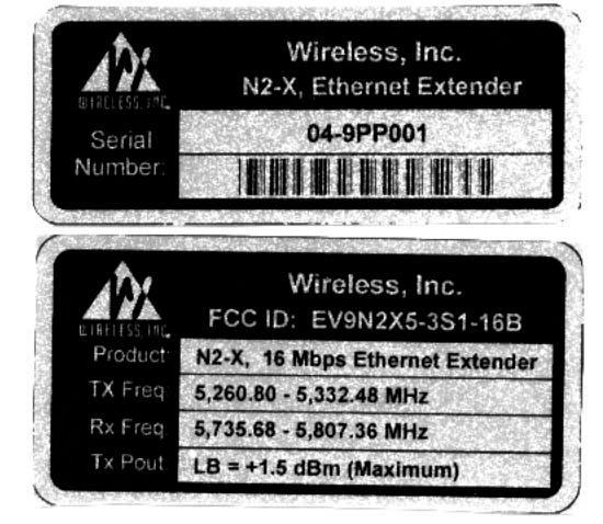
EV9N2X5-3S1-16B
Wireless Inc
Click to zoom
Application Details
- Equipment Class
- NII - Unlicensed National Information Infrastructure TX
- Date of Grant
- Jan 23, 2000
- Application Purpose
- Original Equipment
- Date of Application
- Jul 02, 1999
- Frequency Range
- 5260.00000000 - 5330.00000000
- Company
- Wireless Inc
- Country
- United States
Documents & Files
Document Text
Text extracted from the exhibit documents filed with the FCC. Open a document above to read the original.
Users Manual
N2-X Ethernet Extender Installation and Operations Manual Part Number 281-104101-201 Version 0.1 February 1999 Wireless, Inc. 19 Davis Drive Belmont, CA 94002-3001 ii N2-X Ethernet Extender Installation and Operation Manual Notice Information in this document is subject to change without notice. No part of this document may be reproduced or transmitted in any form or by any means, electronic or mechanical, for any purpose, without the express written permission of Wireless, Inc. © Copyright 1999, Wireless, Inc. All rights reserved. N2-Ethernet Extender TM and ACCESS TM Series are trademarks of Wireless, Inc. iii N2-X Ethernet Extender Installation and Operation Manual Table of Contents 1.0General Overview ...............................................................................................................................1 1.1N2-ACCESS Series Product Family................................................................................................1 1.2Introduction to the N2- X Ethernet Extender ..............................................................1 1.3Regulatory Information .........................................................................................................2 2.0N2- X Ethernet Extender Product Profile .........................................................................................3 2.1General Overview ..................................................................................................................3 2.2Specifications .........................................................................................................................7 2.3User Interfaces.....................................................................................................................12 2.4Alarms, Indicators and Displays (Outdoor Unit) .............................................................17 2.5Theory of Operation ............................................................................................................18 3.0Equipment Installation and Commissioning .................................................................................21 3 . 1Installation.............................................................................................................................21 3.2Data Connectors..................................................................................................................28 3.3Outdoor RF Unit Installation ..............................................................................................32 3 . 4Commissioning....................................................................................................................36 4.0Maintenance and Troubleshooting ................................................................................................39 4.1N2- X Ethernet Extender Maintenance .............................................................................39 4.2Identifying and Resolving Receive Signal Strength Issues..........................................40 4.3N2- X Ethernet Extender Digital Board Switch Settings ................................................42 4.4Where to Get Further Assistance .....................................................................................47 4.5Return Procedure ................................................................................................................48 Appendix ANetwork Management ..........................................................................................................A-1 Appendix B Installation Instructions ........................................................................................................B-1 Appendix CAdjustable Panel Antenna Mount .......................................................................................C-1 iv N2-X Ethernet Extender Installation and Operation Manual Figures Figure 2.1 Typical Deployment of a N2-X Ethernet Extender in a Point-to-Point Configuration 4-5 Figure 2.2 User Interfaces........................................................................................................................12 Figure 2.3 Outdoor Unit, Interior Interfaces ...........................................................................................13 Figure 2.4 N2- X Ethernet Extender Bock Diagram ..............................................................................17 Figure 3.1 Power Cord Connection .........................................................................................................23 Figure 3.2a Upper Pole Mounting Bracket ..............................................................................................24 Figure 3.2b Upper Pole Mounting Bracket Equipment .........................................................................24 Figure 3.2c Lower Pole Mounting Bracket ..............................................................................................25 Figure 3.2d Lower Pole Mounting Bracket Equipment .........................................................................25 Figure 3.3a V-Clamps and Hardware ......................................................................................................26 Figure 3.3b V-Clamps and Hardware (Rear View) ................................................................................26 Figure 3.4 N-Type Antenna and Ground Connections .......................................................................27 Figure 4.1 Frequency Selection for the N2-X Ethernet Extender Radio...........................................40 Figure B.1 Two Foot Diameter Antenna ...............................................................................................B-1 Figure B.2Mount Configuration.............................................................................................................B-3 Figure B.3 Mounting Hardware Packed ................................................................................................B-5 Figu…
Text truncated - open the document above for the full version.
Users Manual
Page 1 of 3 Please make the following changes to the N2-X Ethernet Extender Manual: Change antenna gain numbers (dBi) in Table 3.1 to values shown below, and add text between table heading and table as shown: Table 3.1 - Maximum Transmit Power Level Setting vs. Antenna Type (for compliance with FCC EIRP limits) in the 5.3 GHz band Per the following table, in the 5.3 GHz band the highest power setting (approximately +12 dBm) can only be installed with the lowest gain antenna which is the 6” Flat Panel Plane Polarized (DFPD.5-52) with 17.5 dBi. Each radio is shipped from the factory with a standard 6’ coaxial cable for connection between the radio and the antenna. The cable has a nominal loss of approximately 2.6 dB. UNII radios are covered under CFR 47 FCC part 15, 15.407 Subpart E. 15.407.a.2 which states Ptransmit = 11 dBm + 10 log B where B is the -26 dB BW with a 6 dBi antenna. Above 6 dBi antenna gain there is a 1:1 reduction in Ptransmit to maintain the same MAXIMUM EIRP. This is accomplished by the changes in output power setting for the alternative antennas. The FCC EIRP limit for the 5.3 GHz band with our transmitter bandwidth is +28 dBm. With the transmit power set to +12 dBm, the EIRP with the 6” Flat Panel antenna, and standard 6’ coaxial cable will be: 12 dBm + 17.5 dBi –2.6 dB = 26.9 dBm. Antenna TypeManufacturer P/NMaximum Transmit Power Setting (dBm) 2’ diameter dish with radome, Plane Polarized, 28.1 dBiGabriel SSP2-52ARI0 2’ diameter dish with radome, Dual Polarized, 28.1 dBiGabriel SSD2-52ARI0 6” Flat Panel, Plane Polarized, 17.5 dBiGabriel DFPD.5-52+12 12” Flat Panel, Plane Polarized, 23 dBiGabriel DFPD1-52+4 24” Flat Panel, Plane Polarized, 27.5 dBiGabriel DFPD2-520 Page 2 of 3 Please insert the following in section 2.3 on page 10 between the last paragraph in the text that describes the “outdoor unit” interfaces and Table 2.4. This is a duplicate of the above statements. Table X.X - Maximum Transmit Power Level Setting vs. Antenna Type (for compliance with FCC EIRP limits) in the 5.3 GHz band Per the following table, in the 5.3 GHz band the highest power setting (approximately +12 dBm) can only be installed with the lowest gain antenna which is the 6” Flat Panel Plane Polarized (DFPD.5-52) with 17.5 dBi. Each radio is shipped from the factory with a standard 6’ coaxial cable for connection between the radio and the antenna. The cable has a nominal loss of approximately 2.6 dB. UNII radios are covered under CFR 47 FCC part 15, 15.407 Subpart E. 15.407.a.2 which states Ptransmit = 11 dBm + 10 log B where B is the -26 dB BW with a 6 dBi antenna. Above 6 dBi antenna gain there is a 1:1 reduction in Ptransmit to maintain the same MAXIMUM EIRP. This is accomplished by the changes in output power setting for the alternative antennas. The FCC EIRP limit for the 5.3 GHz band with our transmitter bandwidth is +28 dBm. With the transmit power set to +12 dBm, the EIRP with the 6” Flat Panel antenna, and standard 6’ coaxial cable will be: 12 dBm + 17.5 dBi –2.6 dB = 26.9 dBm. Antenna TypeManufacturer P/NMaximum Transmit Power Setting (dBm) 2’ diameter dish with radome, Plane Polarized, 28.1 dBiGabriel SSP2-52ARI0 2’ diameter dish with radome, Dual Polarized, 28.1 dBiGabriel SSD2-52ARI0 6” Flat Panel, Plane Polarized, 17.5 dBiGabriel DFPD.5-52+12 12” Flat Panel, Plane Polarized, 23 dBiGabriel DFPD1-52+4 24” Flat Panel, Plane Polarized, 27.5 dBiGabriel DFPD2-520 Page 3 of 3 Table X.X - Maximum Transmit Power Level Setting vs. Antenna Type (for compliance with FCC EIRP limits) in the 5.7 GHz band, original and July 31, 1998 rules Per the following table, in the 5.7 GHz band the highest power setting (approximately +12 dBm) can only be installed with the lowest gain antenna which is the 6” Flat Panel Plane Polarized (DFPD.5-52) with 17.5 dBi. Each radio is shipped from the factory with a standard 6’ coaxial cable for connection between the radio and the antenna. The cable has a nominal loss of approximately 2.6 dB. UNII radios are covered under CFR 47 FCC part 15, 15.407 Subpart E. 15.407.a.3 which states Ptransmit = 17 dBm + 10 log B where B is the -26 dB BW with a 6 dBi antenna. Above 6 dBi antenna gain there is a 1:1 reduction in Ptransmit to maintain the same MAXIMUM EIRP. This is accomplished by the changes in output power setting for the alternative antennas. The original FCC EIRP limit for the 5.7 GHz band with our transmitter bandwidth is +33 dBm. With the transmit power set to +12 dBm, the EIRP with the 6” Flat Panel antenna, and standard 6’ coaxial cable will be: 12 dBm + 17.5 dBi –2.6 dB = 26.9 dBm. The corresponding settings are included in the following table. Antenna TypeManufacturer P/NMaximum Transmit Power Setting (dBm) 2’ diameter dish with radome, Plane Polarized, 28.1 dBiGabriel SSP2-52ARI0 2’ diameter dish with radome, Dual Polarized, 28.1 dBiGabriel SSD2-52ARI0 6” Flat Panel, Plane Polarized, 17.5 dBiGabriel DFPD.5-52+12 12” Flat Panel, Plane Polarized, 23 dBiGabriel DFPD1-52+8 24” Flat Panel, Plane Polarized, 27.5 dBiGabriel DFPD2-52+4 The FCC will also allow higher EIRP for point to point links with higher gain antennas. Page 703 of the FCC document, CFR 47 FCC part 15, 15.407 Subpart E, FR 40836, July 31, 1998 has the provisions for these power limits. The path length isn’t increased, since the 5.3 GHz transmitter isn’t allowed the higher EIRP. We recommend the higher power settings only when absolutely necessary. This rule states " fixed pt-pt U-NII devices operating in this band may employ transmitting antennas with directional gain up to 23 dBi without the corresponding reduction in transmitter peak output power or peak power spectral density”. Also above 23 dBi antenna gain there is a 1:1 reduction in Pout to maintain the same MAX EIRP. We are in compliance even at the maximum antenna gain and transmitter power, since the corresponding output power is over +27 dBm in our BW and the resulting EIRP for a 6 dBi antenna is +33 dBm. This EIRP limit is further …
Text truncated - open the document above for the full version.
Users Manual
N2-X Ethernet Extender Installation and Operation Manual Part Number 281-104101-201 Version 1.0 December 1999 Wireless, Inc. 5452 Betsy Ross Drive Santa Clara, CA 95054-1101 ii N2-X Ethernet Extender Installation and Operation Manual Notice Information in this document is subject to change without notice. No part of this document may be reproduced or transmitted in any form or by any means, electronic or mechanical, for any purpose, without the express written permission of Wireless, Inc. © Copyright 1999, Wireless, Inc. All rights reserved. N2-X Ethernet Extender™ and ACCESS™ Series are trademarks of Wireless, Inc. iii N2-X Ethernet Extender Installation and Operation Manual Table of Contents 1.0 General Overview ................................................................................................................. 1 1.1 N2-ACCESS Series Product Family ......................................................................... 1 1.2 Introduction to the N2-X Ethernet Extender .............................................................. 1 1.3 Regulatory Information .............................................................................................. 2 2.0 N2-X Ethernet Extender Product Profile ............................................................................... 3 2.1 General Overview...................................................................................................... 3 2.2 Specifications ............................................................................................................ 7 2.3 User Interfaces ........................................................................................................ 10 2.4 ODU Performance Monitoring ................................................................................. 15 2.5 Theory of Operation ................................................................................................ 15 3.0 Equipment Installation and Commissioning ........................................................................ 21 3.1 Installation ............................................................................................................... 21 3.2 Ethernet Data Connectors....................................................................................... 24 3.3 Connect the Power Supply...................................................................................... 25 3.4 Outdoor RF Unit Installation .................................................................................... 26 3.5 Commissioning ........................................................................................................ 33 4.0 Maintenance and Troubleshooting...................................................................................... 37 4.1 N2-X Ethernet Extender Maintenance .................................................................... 37 4.2 Identifying and Resolving Receive Signal Strength Issues..................................... 38 4.3 Dip Switch Function and Configuration ................................................................... 40 4.4 Where to Get Further Assistance ............................................................................ 42 4.5 Return Procedure .................................................................................................... 43 Appendix A Grounding Practices and Lightning Protection Information....................................... A-1 Appendix B Installation Instructions.............................................................................................. B-1 Appendix C Quick Align Antenna Mount Installation ....................................................................C-1 Appendix D Adjustable Panel Antenna Mount ..............................................................................D-1 iv N2-X Ethernet Extender Installation and Operation Manual v N2-X Ethernet Extender Installation and Operation Manual Figures Figure 2.1 Typical Deployment of a N2-X Ethernet Extender in a Point-to-Point Configuration ...................................................................................... 5-6 Figure 2.2a Outdoor Unit, Front View............................................................................................14 Figure 2.2b Outdoor Unit, Back View ............................................................................................ 14 Figure 2.3 N2-X Ethernet Extender Bock Diagram ................................................................ 19-20 Figure 3.1 Power Cord Connection ............................................................................................. 25 Figure 3.2 Outdoor Unit Mounting Hardware .............................................................................. 26 Figure 3.3 Attaching the Pole Mount Adapter Bracket ................................................................ 27 Figure 3.4 Mounting the Outdoor RF Unit to the Bracket ............................................................ 28 Figure 3.5a Mounting Bracket Latch and Stud Mount Detail......................................................... 29 Figure 3.5b Locking the Mounting Hardware ................................................................................ 30 Figure 3.6a N-Type Antenna and Siamesed Ethernet/Power Connections .................................. 31 Figure 3.6b Ground Connection ....................................................................................................32 Figure 4.1 Frequency Selection for the N2-X Ethernet Extender Radio ..................................... 38 Figure 4.2 Dip Switch Access and Configuration Information ..................................................... 41 Figure B.1 Two Foot Diameter Antenna ..................................................................................... B-1 Figure B.2 Mount Configuration ................................................................................................…
Text truncated - open the document above for the full version.
Users Manual
Corrections to N2-X Ethernet Extender Installation and Operation Manual (12-17-99 .pdf version) Page viii Change second paragraph to read: Referencing OET Bulletin 65 (Edition 97-01, August 1997) from the Federal Communications Commission's Office of Engineering & Technology, limits for the maximum permissible exposure (MPE) to microwave signals have been adopted by the FCC for General Population/Uncontrolled environments. This limit is 1.0 mW/cm 2 , with averaging time of thirty minutes. Change 8 th paragraph to read For example, a logarithmic power gain of 17.5 dB is equal to a numeric gain of 56.23. Change 9 th paragraph to read Assuming (1) maximum output power from the N2-X Ethernet Extender (+12 dBm[15.8 mW]), (2) no signal loss in the cable connecting the N2-X Ethernet Extender to the antenna, and (3) the use of a 17.5 dBi gain flat panel antenna, the 1.0 mW/cm 2 MPE power density limit would be reached at a distance of approximately 8.4 cm. The N2-X Ethernet Extender is classified as a fixed installation product, and per FCC policy guidelines regarding MPE, antenna installers must maintain a separation distance of 20 cm or the resulting calculation of distance from transmitter EIRP, whichever is the greater distance. Page B-2 Make the following changes to Table B.1: - Eliminate last column , heading: 2.5ft (0.8mm) antenna - Correct heading of second column to read: 2ft. (0.6m) Antenna - Correct dimension K, column 2 to read: 24" (610mm) Page 9 Change footnote to Table 2.3 - Recommended Antennas to read: *The 4-foot dish antennas are for use outside the USA only, and are not FCC compliant.
Users Manual
P.O. Box 70, Scarborough, Maine 04070 U.S.A. Tel: 207-883-5161Fax: 207-883-4469 email: [email protected]: http://www.gabrielnet.com 58 5.250 - 5.850 GHz Flat Panel Antennas 5.250 - 5.850 GHz Electrical Specifications Associated Equipment InformationPages Point-to-Point Antenna Specifications................................. 14 - 111 Special Application Antennas.............................................135 - 145 Antenna Mounts & Reference Dimensions.......................112 - 134 Radomes................................................................................122 - 124 Tower Accessories.............................................................146 - 154 Transmission Lines..............................................................155 - 243 Dry Air Pressurizers............................................................244 - 253 5 GHz Directional Flat Panel Antenna 5 GHz - Spread Spectrum / NII Band Directional Flat Panel Antenna (for Point-to-Point applications) Facts & Features • Gabriel Quality and Dependability. • Lightweight and durable construction. • Quick and easy installation. • Feed input, Type N Female connector. (Other types available on request.) • Input connector positioned on back of antenna assembly. • Antenna supplied with paintable rigid radome. • All Gabriel antennas meet or exceed Standards EIA-195-C and EIA-222-F. • Antenna accommodates +/-20° elevation adjustment. (specific installation limitations may apply) • Mini-Mounts accommodate a 1.9 in. to 4.5 in. (48 to 114 mm) O.D. mast pipe. Quick-Align Mounts mount to a 2.375 in. (60 mm) O.D. mast pipe. An optional 1.9 in. (48 mm) to 4.5 in. (114 mm) Mast Clamp Kit is available on request for the Quick-Align Mount. • To adapt the Quick Align Mount for use on a 1.9 in. to 4.5 in. O.D. mast pipe order Mast Clamp Kit MCKQ-19-45 • Special colors and / or logos available on request. • Dual band models are available. Diagonal - Directional Flat Panel - Plane Polarized DFPS.5-52**0.5(0.15)MM17.518.0 18.419.030351.50(14.0) DFPD1-521(0.3)MM23.023.5 23.99.430431.50(14.0) DFPD1-52 (M1)1(0.3)QAM23.023.5 23.99.430431.50(14.0) DFPD2-522(0.6)QAM27.528.0 28.44.630461.50(14.0) NOTE: Product information subject to change without notice. 5.250 - 5.850 VSWR (R.L. max. dB) Frequency GHz Model Number Diameter ft (m) Mount Type Gain at Low Mid High dBi Nominal Mid-Band Beamwidth degrees XPD dB F/B ratio dB MM=Mini - Mount QAM=Quick Align Mount ** Note: The DFPS.5-52 antenna model is square in configuration.
Cover Letter(s)
FCC ID: EV9N2X5-3S1-16B WIRELESS, INC.. ELECTRONIC COMPLIANCE LABORATORIES, INC. 1249 Birchwood Drive, Sunnyvale, California 94089 408/747-1490 { HYPERLINK http://www.eclabs.com } 800/707-LABS September 28, 1999 Federal Communications Commission Equipment Approval Services 7435 Oakland Mills Road Columbia, MD, 21046 Subject: Correspondance Reference Number: 8662 FCC ID: EV9N2X53S116B 731 Confirmation #: EA94738 Ms. Elliott, I apologize for just now getting back to you on the above-mentioned correspondence letter. The client has made several modifications to EUT and the plan was to submit a replacement package with all the new data and technical report. Included in the ”new” submittal package would be the ID Label as well as the location. Because the enclosure was to change the actual location was not yet defined. I was waiting to complete the new package. As far as the schematics, block diagrams and users manual the same thing is applicable. Please excuse my unorthodox approach but the replacement package will be submitted at the same time as this response. There was an error when submitting the initial 731 form with reference to the FCC ID number and at this time I would like to request that the 731 form be changed to the correct text and the entire application be updated with the following: INCORRECT FCC ID NUMBER: EV9N2X53S116B CORRECT FCC ID NUMBER:EV9N2X5-3S1-16B Please note the only difference is the addition of the dashes... I’ve included a copy of the LABEL in an attached file titled “Labels”. Please refer to the newly filed information packet for the Schematics, Blk. Diagrams and the replacement Users Manual located in APPENDIX J, titled Confidential Information. Again I apologize for any inconvenience or delays this may have caused. If there is anything else I need to do to correct this problem please do not hesitate to contact me at 408/747-1490 or by email at: [email protected] Sincerely, Chip Matheny Chief Technical Officer Filename:FCCGenericResponseLetter Directory:\\SCHWEIN-HUND\SERVER\Report Templates\FCC Template:C:\Program Files\Microsoft Office\Templates\Normal.dot Title:cover Subject:submission cover letter Author:N/A Keywords: Comments: Creation Date:09/29/99 11:10 PM Change Number:2 Last Saved On:09/29/99 11:10 PM Last Saved By:Chip Matheny Total Editing Time:21 Minutes Last Printed On:09/29/99 11:39 PM As of Last Complete Printing Number of Pages:1 Number of Words:260 (approx.) Number of Characters:1,483 (approx.)
Cover Letter(s)
FCC ID: EV9N2X5-3S1-16B WIRELESS, INC. ELECTRONIC COMPLIANCE LABORATORIES, INC. 1249 BIRCHWOOD DRIVE, SUNNYVALE, CALIFORNIA 94089 408/747-1490 www.eclabs.com 800/707-LABS September 30, 1999 Greg Czumak Federal Communications Commission Equipment Authorization Division Applications Processing Branch 7435 Oakland Mills Rd Columbia, MD 21046 Greg, Please find in the attached files a revised test report and supporting exhibits and documentation for the Wireless, Inc. N2-X Ethernet Extender Bridge product, submitted for approval and certification on or about July 12 th , 1999. FCC ID: EV9N2X5-3S1-16B, Confirmation number: EA94738 My Client has made several changes to the production version so please except the contents of this package for review and disregard what was previously submitted. The N2-X 5.3 GHz Radio has been modified and improved for performance. This product has variable power settings for each of the eight- (8) channels. The unit was tested at each of the power levels for the LO, MID and HIGH channels configured with four (4) different antenna types for your review. The gain of the antennas is paired with the various power settings to meet the limits called out in CFR Title 47, Part 15 of the Rules and Regulations. The report reflects the new limits called out in 15.407. Please review the file titled “N2-X differences” for a description of the design changes in the latest production model. Also enclosed is an original Agent Authorization letter from Wireless, Inc. authorizing Electronic Compliance Laboratories, Inc. to act on their behalf. In addition, all of the exhibits thought necessary to support this application are included, along with a confidentiality package. Due to size of the package the format in which I am submitting is a little different. The report document 9080501A references various appendices, Each appendix is a separate PDF file saved as “APPENDIX A” for example. Let me know if you have any problems with the format and I’ll make the adjustments as you see fit. The Theory of Operations can be located in “APPENDIX J” with the other confidential information. The following documents are being sent to replace the exhibits of the application presently in Technical Review. These documents are being submitted for FINAL consideration for Certification: FCC ID: EV9N2X5-3S1-16B WIRELESS, INC. ELECTRONIC COMPLIANCE LABORATORIES, INC. 1249 BIRCHWOOD DRIVE, SUNNYVALE, CALIFORNIA 94089 408/747-1490 www.eclabs.com 800/707-LABS 9080501A.PDFTest report Appendix A.PDFRadiated/Conducted results Appendix B.PDFExpalnation of Test Methodology Appendix C.PDFPeak Power Measurements Appendix D.PDFOut of Band Data and Plots Appendix E.PDFSet-up Configurations/Photos Appendix F.PDFRestricted Band Data /Harmonics Appendix G.PDFAntenna Data Sheets Appendix H provided in the report Appendix I.PDFEUT Photos Appendix J.PDFConfidentiality Material/ Proprietary Info. Labels.jpegLabel Photos Letters.PDFMisc. Letters 5.3ghzMPEMPE distance calculations Greg, I received the formal pre-grant sample request for both of the units. My hopes are that you would review this package and let me know if this will still be a requirement. The unit was tested very thoroughly and they are pretty solid radios. I was looking at my schedule and thinking about yours, and this will be just another thing I’ll have to prepare for. The stack is getting higher, so as soon as you know something. I would appreciate a notification and at that point, if it’s not a problem, I would request to take your earliest available opening and I will make sure the unit or units will be hand carried there for testing. Just an effort to try and expedite the time involved and to eliminate any complications or hassles with the shipping or whatever... If there are any questions or problems please don’t hesitate to contact me at the number listed above, or by email, [email protected]. I look forward to hearing from you and I’ll talk to you then. Sincerely, Chip Matheny Chief Technical Officer
Cover Letter(s)
May 26, 1999 Federal Communications Commission Authorization and Evaluation Division Laboratory Division 7435 Oakland Mills Road Columbia, MD 21046 Sir / Madam: We, Wireless Inc., hereby authorize Electronic Compliance Laboratories to act on our behalf in all matters relating to applications for equipment authorization, including the signing of all documents relating to these matters. Any and all acts carried out by Electronic Compliance Laboratories on our behalf shall have the same effect as acts of our own. We also hereby certify that no party to the applications authorized hereunder is subject to a denial of benefits, that includes FCC benefits, pursuant to Section 5301 of the Anti- Drug Abuse Act of 1988, 21 U.S.C. 853(a). This agreement expires one year from the current date. Sincerely yours, Bill Anderson Director of Product Development Wireless Inc. Wireless, Inc. 19 Davis Drive Belmont, CA 94002 Phone: 650-595-3300 FAX: 650-595-4907
Cover Letter(s)
October 1, 1999 Greg Czumak Federal Communications Commission Equipment Authorization Division Applications Processing Branch 7435 Oakland Mills Rd Columbia, MD 21046 FCC ID: EV9N2X5-3S1-16B, Confirmation number: EA94738 Greg, Please find in the attached files, exhibits and documentation for the Wireless, Inc. N2-X Ethernet Extender Bridge product. These are the remaining documents which did not get uploaded sucessfu…
Text truncated - open the document above for the full version.
Contact Information
Applicant
Robert A Czerwinski(Director, Compliance/QA)
Technical Contact
T.N. Cokenias ConsultingThomas n. Cokenias
P.O. Box 1086 · El Granada, California · United States
Technical Specifications
| # | Rule Parts | Frequency Range | Power Output | Tolerance |
|---|---|---|---|---|
| 1 | 15E | 5.26 GHz - 5.33 GHz | 16.00 mW | ppm |
Other Applications from Wireless Inc
EV9N2WLAX-5G7
Jan 17, 2001Link AX ATM25 Extender
Equipment Class
NII - Unlicensed National Information Infrastructure TX
EV9N2WLAX-5G3
Dec 11, 2000UNII WLAN
Equipment Class
NII - Unlicensed National Information Infrastructure TX
EV9N2-4XE1-5G3
May 10, 2000Point to Point Transceiver
Equipment Class
NII - Unlicensed National Information Infrastructure TX
EV9N2-4XE1-5G7
May 10, 2000Point to Point Data Transceiver
Equipment Class
NII - Unlicensed National Information Infrastructure TX
EV9N2X5-7S1-16B
Jan 23, 2000NII - Unlicensed National Information Infrastructure TX
Equipment Class
NII - Unlicensed National Information Infrastructure TX