EV9WAL2-4S1-01Point-to-Point Data Transmitter
Wireless Inc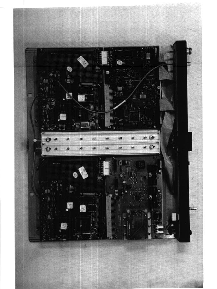
Click to zoom
Application Details
- Equipment Class
- DSS - Part 15 Spread Spectrum Transmitter
- Date of Grant
- Oct 18, 1998
- Application Purpose
- Original Equipment
- Date of Application
- Aug 12, 1998
- Equipment Note
- Point-to-Point Data Transmitter
- Frequency Range
- 2466.50000000 - 2466.50000000
- Company
- Wireless Inc
- Country
- United States
Documents & Files
Document Text
Text extracted from the exhibit documents filed with the FCC. Open a document above to read the original.
RF Exposure Info
August 17, 1998 Federal Communications Commission Equipment Authorization Division 7435 Oakland Mills Road Columbia, MD 21046 Subject: Maximum Permissible Exposure calculations for FCC ID: EV9WAL2-4S1-01 To whom it may concern, Multipoint is submitting a low power transmitter for the Access Link. The unit has a low power direct sequence spread spectrum radio operating in the 2480 - 2483.5 MHz range with an output power of 76.9 mW. Assuming a worst case of no duty cycle. For an Isotropic radiator the surface area of a sphere can be used to determine the area over which the transmitter energy is radiated. Surface area of a sphere = 4*Π*radius 2 In the case where there is antenna gain, the worst case energy density is increased by the antenna gain. The exposure level can be calculated as follows for the antenna gain: MPE distance = (output power*duty cycle*10(antenna gain/10)/(4*Π*Exposure Limit (mW/cm 2 ) 1/2 EV9WAL2-4S1-01 MPE calculation California Amplifier 21dBi QLP Parabolic Antenna MPE distance = (76.9 mW*1*21.0/4*3.14*1) 1/2 = 11.3 cm = 4.45 in California Amplifier 24dBi QLP Parabolic Antenna MPE distance = (76.9 mW*1*24.0/4*3.14*1) 1/2 = 12.1 cm = 4.77 in Gabriel 26 dBi Grid Parabolic Antenna MPE distance = (76.9 mW*1*26.0/4*3.14*1) 1/2 = 12.6 cm = 4.96 in Gabriel 21 dBi Solid Parabolic Antenna MPE distance = (76.9 mW*1*21.0/4*3.14*1) 1/2 = 11.3 cm = 4.43 in Gabriel 17 dBi Panel Antenna MPE distance = (76.9 mW*1*17.0/4*3.14*1) 1/2 = 10.2 cm = 4.01 in Cushcraft 7 dBi Panel Antenna MPE distance = (76.9 mW*1*7.0/4*3.14*1) 1/2 = 6.54cm = 2.57 in Andrew 24 dBi Grid Parabolic Antenna MPE distance = (76.9 mW*1*24.0/4*3.14*1) 1/2 = 12.1 cm = 4.77 in COMSAT RSI 21 dBi Solid Parabolic Antenna MPE distance = (76.9 mW*1*21.0/4*3.14*1) 1/2 = 11.3 cm = 4.43 in If you have any questions please do not hesitate to call me. Sincerely, Chris Byleckie Technical Director Electronic Compliance Laboratories
Test Report
A801005.DOC1 CFR Title 47 PartsCFR Title 47 Parts 15.247 cer15.247 certtificationification FCC ID:FCC ID: EV9WAL2-4S1-01 EV9WAL2-4S1-01 EMI TEST REPORTEMI TEST REPORT onon Access LinkAccess Link California Amplifier 21dBi Parabolic AntennaCalifornia Amplifier 21dBi Parabolic Antenna California Amplifier 24dBi Parabolic AntennaCalifornia Amplifier 24dBi Parabolic Antenna Gabriel 26 dBi Parabolic AntennaGabriel 26 dBi Parabolic Antenna Gabriel 21 dBi Parabolic AntennaGabriel 21 dBi Parabolic Antenna Gabriel 17 dBi Panel AntennaGabriel 17 dBi Panel Antenna Cushcraft 7 dBi Panel AntennaCushcraft 7 dBi Panel Antenna Andrew 24 dBi Parabolic AntennaAndrew 24 dBi Parabolic Antenna COMSAT RSI 21 dBi Parabolic AntennaCOMSAT RSI 21 dBi Parabolic Antenna Prepared ForPrepared For Multipoint NetworksMultipoint Networks 19 Davis Drive19 Davis Drive Belmont, CA 94002-3001Belmont, CA 94002-3001 TEL: (650)595-3300TEL: (650)595-3300 FAX: (650)595-4907FAX: (650)595-4907 Prepared byPrepared by Electronic Compliance Laboratories, Inc.Electronic Compliance Laboratories, Inc. 1249 Birchwood Drive1249 Birchwood Drive Sunnyvale, CA 94089Sunnyvale, CA 94089 408/747-1490408/747-1490 Test Report Number: A801005Test Report Number: A801005 Date of Test: April14,15, and 18, 1998Date of Test: April14,15, and 18, 1998 If this document is reproduced, it must be reproducedIf this document is reproduced, it must be reproduced in its entirety.in its entirety. A801005.DOC2 Table of Contents 1.0 Certification of Compliance .........................................................................3 2.0 General Information ......................................................................................4 3.0 Test Facility....................................................................................................5 4.0 Test equipment..............................................................................................5 5.0 Data Reporting Format..................................................................................6 6.0 Detector Functions........................................................................................6 7.0 Frequency Range of Investigation................................................................6 8.0 FCC Class Types...........................................................................................7 9.0 FCC Limits......................................................................................................8 9.1 Conducted Emission Limits..................................................................8 9.2 Radiated Emission Limits.....................................................................8 10.0 Test Methods................................................................................................9 10.1 Line Conducted Emissions Test Procedure.......................................9 10.2 Line Conducted Emissions Test Example..........................................9 10.3 Radiated Emissions Test Procedure..................................................10 10.4 Radiated Emissions Test Example....................................................10 11.0 Labeling Requirements...............................................................................11 12.0 Summary of Measurements........................................................................12 APPENDIX A Spread Spectrum Plots.................................................................16 APPENDIX B Restricted Band Data....................................................................29 APPENDIX C Radiated Emissions.......................................................................38 APPENDIX D Antenna and Antenna Connector Drawings................................41 APPENDIX E Set-up Photos................................................................................51 APPDENIX F Direct Sequence Measurement Techniques................................57 APPENDIX G Processing Gain............................................................................61 A801005.DOC3 1.0 Certification of Compliance Description:Access Link The EUT consists of the following: Access Link 1 x DS1 Terminal unit (TU) RG-8 Type N coaxial cable TU to antenna jumper California Amplifier 21dBi QLP Parabolic Antenna P/N 130093 California Amplifier 24dBi QLP Parabolic AntennaP/N 130094 Gabriel 26 dBi Grid Parabolic AntennaP/N GHF4-23A Gabriel 21 dBi Solid Parabolic AntennaP/N RFF2-23BSE Gabriel 17 dBi Panel AntennaP/N SSFP23-17 Cushcraft 7 dBi Panel AntennaP/N S2307 Andrew 24 dBi Grid Parabolic AntennaP/N KPR3F-23 COMSAT RSI 21 dBi Solid Parabolic AntennaP/N P-24A24N-1 Model Number:1 x DS1 2.4 GHz Serial Number: 00001 Applicant: Mutlipoint Networks Type of Test: FCC-15, Class B (Certification) part 15.247; Date of Test: April 14, 15 and 18, 1998 Tested By:Suresh Kondapalli The above equipment was tested by Electronic Compliance Laboratories, Inc. and found to be in compliance with the requirements set forth in the FCC Rules and Regulations, Part 15, Subpart C (15.203, 15.205, 15.207, 15.209, 15.247). The equipment, in the configuration described in this report, shows that the maximum emission levels emanating from this equipment are within the compliance requirements. ____________________________________ Chris ByleckieDate Technical Director A801005.DOC4 2.0 General Information Applicant:Mutlipoint Networks 19 Davis Drive. Belmont, CA 94002-3001 Contact Person: Bob Czerwinski Equipment Under Test: Access Link Model Number: 1 x DS1 2.4 GHz Serial Number: 00001 FCC ID#:WEGWAL2-4S1-01 Report Number: A801005 Date of Test: April 14,15 and 18, 1998 Manufacturer: Mutlipoint Networks Type of Test:FCC part 15, Subpart C, (15.203, 15.205, 15.209, 15.247), Class A Digital Device. Frequency Range:30 MHz to 1000 MHz - Radiated Emissions, Class A 2400 MHz to 2483.5 MHz - part 15.247 Up to the 10th harmonic of the fundamental (24.835 GHz) part 15.35(a) Summary Pass/Fail: Passed 15.209 Radiated Emissions: The Access Li…
Text truncated - open the document above for the full version.
Test Report
Addendum to Report A801005Addendum to Report A801005 FCC ID:FCC ID: EV9WAL2-4S1-01 EV9WAL2-4S1-01 EMI TEST REPORTEMI TEST REPORT onon Access LinkAccess Link Prepared ForPrepared For Multipoint NetworksMultipoint Networks 19 Davis Drive19 Davis Drive Belmont, CA 94002-3001Belmont, CA 94002-3001 TEL: (650)595-3300TEL: (650)595-3300 FAX: (650)595-4907FAX: (650)595-4907 Prepared byPrepared by Electronic Compliance Laboratories, Inc.Electronic Compliance Laboratories, Inc. 1249 Birchwood Drive1249 Birchwood Drive Sunnyvale, CA 94089Sunnyvale, CA 94089 408/747-1490408/747-1490 Test Report Number: A801005Test Report Number: A801005-add-add Date of Test: April14,15, and 18, 1998Date of Test: April14,15, and 18, 1998 If this document is reproduced, it must be reproducedIf this document is reproduced, it must be reproduced in its entirety.in its entirety. 15.247 (b) Maximum Peak Output Power The Access Link was placed in continuous transmit mode and tested at 2417 and 2466.5 MHz. Table 1 shows the maximum peak power of the transmitter at these three frequencies, respectively. The highest level (at 2466.5 MHz) is at +18.86 dBm, or 76.9milliwatts. Maximum permitted is 1.0 watts, or +30 dBm. The Access Link output was connected to a Spectrum Analyzer through a 20dB pad. Frequency, MHzReading, dBmPad & Cable Loss, dB Corrected Reading, dBm / mW 2417.0-2.5020.417.90 dBm / 61.6 mW 2466.5-1.5020.418.86 dBm / 76.9 mW Table 1. Summary of Access Link Output Power(Conducted) The Access Link was tested with 8 different antennas. The maximum EIRP ( Equivalent Isotropically Radiated Power) for each antenna is : California Amplifier 21dBi QLP Parabolic Antenna Power = 18.86 dBm (peak reading) + 21 dBi ( ant. gain) = +39.86 dBm / 9.68 W EIRP California Amplifier 24dBi QLP Parabolic Antenna Power = 18.86 dBm (peak reading) + 24 dBi ( ant. gain) = +42.86 dBm / 19.3 W EIRP Gabriel 26 dBi Grid Parabolic Antenna Power = 18.86 dBm (peak reading) + 26 dBi ( ant. gain) = +44.86 dBm / 30.6 W EIRP Gabriel 21 dBi Solid Parabolic Antenna Power = 18.86 dBm (peak reading) + 21 dBi ( ant. gain) = +39.86 dBm / 9.68 W EIRP Gabriel 17 dBi Panel Antenna Power = 18.86 dBm (peak reading) + 17 dBi ( ant. gain) = +35.86 dBm / 3.85 W EIRP Cushcraft 7 dBi Panel Antenna Power = 18.86 dBm (peak reading) + 7 dBi ( ant. gain) = +25.86 dBm / 385 mW EIRP Andrew 24 dBi Grid Parabolic Antenna Power = 18.86 dBm (peak reading) + 24 dBi ( ant. gain) = +42.86 dBm / 19.3 W EIRP COMSAT RSI 21 dBi Solid Parabolic Antenna Power = 18.86 dBm (peak reading) + 21 dBi ( ant. gain) = +39.86 dBm / 9.68 W EIRP Manufacturers antenna drawings are in Appendix F. 15.247 (c) Out Of Band Emissions (Not Falling within Restricted Bands) The Access Link was placed in transmit mode at the low (2417 MHz) and the high (2466.5 MHz) channels. The spectrum analyzer was placed in the MAX HOLD mode. Out of Band emissions were investigated and found to be better than 20 dB (in power) below the highest in-band emission. In addition, out of band emissions (radiated) were below the limits specified in 15.209. See Plots in Appendix A. Plot TitleFrequency Range of Plot, MHz Purpose of Plot Out Of Band Emissions Lower Edge 2400 - 2440Show Emissions are down by 20 dB Out Of band Emissions Upper Edge 2440 - 2483.5Show Emissions are down by 20 dB Out Of band Emissions 2417 MHz 0 - 1000 1000 - 2750 2750 - 26,500 Show Emissions are down by 20 dB Out Of band Emissions 2466.5 MHz 0 - 1000 1000 - 2750 2750 - 26,500 Show Emissions are down by 20 dB 15.247 (d). Transmitted Power Density The Access Link exhibits a transmitted power density of less than +8 dBm in any 3 kHz bandwidth over any one second interval. This test was performed in accordance with the guidelines set forth in “Guidance on Measurements for Direct Sequence Spread Spectrum Systems”, as published by Federal Communication, Authorization and Evaluation Division. Please refer to a copy of this document in Appendix J. The Access Link was connected to the Spectrum Analyzer via a short length of test cable (4 inches RG214) and a 20 dB Pad. The detector in the Spectrum Analyzer was set to Peak mode, the resolution and video bandwidths were set to 3 kHz, and the sweep time was set per the following relation: Sweep Time (seconds) = Spectrum Analyzer Span in Hertz Resolution Bandwidth, Hertz For this case, We have a sweep time of 250kHz/3kHZ = 83.3 seconds. Note that the peak level of the Access Link’s Spectral Mask was selected prior to reducing the span to 250 kHz. In this manner, the maximum level was observed and selected for this test. Table 2 below summarizes the results, Plots labeled “Spectral Power Density” are in Appendix A. Frequency, MHzReading dBm 2417.08.00 2466.5.07.00 note; FCC LIMIT< than + 8 dBm Table 2. Summary of Spectral Power Density measurements for the Access Link
Contact Information
Applicant
Robert A Czerwinski(Director, Compliance/QA)
Technical Contact
electronic compliance laboratorieschris byleckie
[email protected]408-747-1490
1249 birchwood drive · sunnyvale, California · United States
Non-Technical Contact
electronic compliance laboratorieschris byleckie
[email protected]408-747-1490
Test Firm
Electronic Compliance LaboratoriesChip Matheny
[email protected]408-747-1490
Technical Specifications
| # | Rule Parts | Frequency Range | Power Output | Tolerance |
|---|---|---|---|---|
| 2 | - | 2.47 GHz - 2.47 GHz | 80.00 mW | % |
Other Applications from Wireless Inc
EV9N2WLAX-5G7
Jan 17, 2001Link AX ATM25 Extender
Equipment Class
NII - Unlicensed National Information Infrastructure TX
EV9N2WLAX-5G3
Dec 11, 2000UNII WLAN
Equipment Class
NII - Unlicensed National Information Infrastructure TX
EV9N2-4XE1-5G3
May 10, 2000Point to Point Transceiver
Equipment Class
NII - Unlicensed National Information Infrastructure TX
EV9N2-4XE1-5G7
May 10, 2000Point to Point Data Transceiver
Equipment Class
NII - Unlicensed National Information Infrastructure TX
EV9N2X5-7S1-16B
Jan 23, 2000NII - Unlicensed National Information Infrastructure TX
Equipment Class
NII - Unlicensed National Information Infrastructure TX