EW4-WLPS3VoIP Mobile Phone Terminal
Mitsumi Electric Co Ltd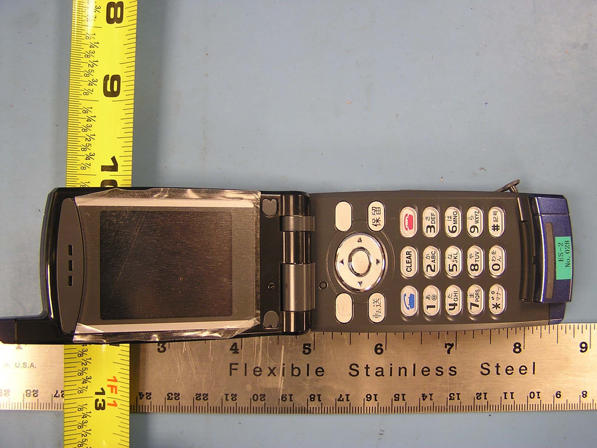
Click to zoom
Application Details
- Equipment Class
- DTS - Digital Transmission System
- Date of Grant
- Sep 26, 2006
- Application Purpose
- Original Equipment
- Date of Application
- Sep 26, 2006
- Equipment Note
- VoIP Mobile Phone Terminal
- Frequency Range
- 2412.00000000 - 2462.00000000
- Company
- Mitsumi Electric Co Ltd
- Country
- Japan
Documents & Files
Document Text
Text extracted from the exhibit documents filed with the FCC. Open a document above to read the original.
Users Manual
MH250 U SERS G UIDE NEC Infrontia Corporation 2006 August NWA-xxxxxx-001 Issue 1.0 LIABILITY DISCLAIMER NEC Infrontia Corporation reserves the right to change the specifications, functions, or features, at any time, without notice. NEC Infrontia Corporation has prepar ed this document for use by its employees and customers. The informat ion contained herein is the property of NEC Infrontia Corporation and sh all not be reproduced without prior written approval from NEC Infrontia Corporation. All brand names and product names on this docu ment are trademarks or registered trademarks of their respective companies. Copyright 2006 NEC Infrontia Corporation User Safety Protocol ............................................................ ...................................................... Important: Read this information before using your MH250 Handset. Observe the following instructions to use this product sa fely, prevent you and other people from possible injury, and protect properties. Improper handling may cause heat, explosion, and fire. Danger Recharge the battery with the matching ba ttery charger (see battery label description). Use the battery only for this MH250 handset system . Do not use it with other electrical devices. Keep the following warnings to prevent the ba ttery pack from heating, explosion, and fire. • Do not throw the battery pack into fire. • Do not solder the battery pack directly. • Do not short the positive (+) and negative (- ) terminal of the battery pack with metal. • Do not poke the battery nor smash it with hammer. Do not disassemble nor modify the battery pack. It has a safety circuit and a damaged circuit may cause heat, explosion, and fire. The internal liquid of the battery pack has strong acid. If t he battery liquid gets into your eye, rinse your eye well with water and consult with a doctor. Do not use, leave, nor recharge the bat tery pack near fire or under the direct sunlight. High temperature may damage the internal safety circuit and may cause malfunct ion of the recharge, heat, explosion, or fire. Warning ............................................................ ...................................................... Do not use the unit when you notice smoke, strange smell or other unusual happenings. It may caus e fire if you continuously us e them. Turn off the power switch of the phone system immediately. For the recharger, disconnect the power plug immediat ely. Confirm that smoke is c eased, and then contact the nearest NEC service office. Never a ttempt to repair those units by yourself. If you had an accident such as dropping the phone and broke the unit, turn off the power of the phone system immediately. For the recharger, disconnect the power plug immediately. Contac t the nearest NEC service office. If you k eep using those units, they may cause fi re or electrical shock. If water smeared into the unit, turn off the power of the phone system immediately. For the recharger, disconnect the power pl ug immediately. Contact with the nearest NEC service office. If you keep using those units, they may cause fi re or electrical shock. Do not insert flammable or metal objects into the units. If a foreign object were accidentally placed into the units, turn off the power of the phone system and plug out the power adapter. Contact the nearest NEC se rvice office. If you keep using those units, they may cause fi re or electrical shock. Pay special attention to children to prevent from similar accidents. Do not attempt to disassemble nor modify the units. It may cause fire, electrical shock, or syst em malfunction. Modification b y a user is prohibited by law. Do not open the units intentionally. It may cause electrical shock or system malfunc tion. Ask test adjustment, and repair of t he units for the nearest NEC service office. Do not twist, put a heavy object, and push the phone system . Such actions may cause damage, fire, or injuries. Do not place a container with water such as a vase, a plant po t, a cup, cosmetics, chemicals, nor a small metal object. Splash ing water over the units and foreign metal object inserted into the units may cause fire or electrical shock. Do not use the unit in a high humid area such as a bathroom or near a humidifier. They may cause fire, electrical shock, or sy stem malfunction. Use the specified power adapter, which is attached to the unit. Other adapters may cause fire or system malfunction. Do not damage, or modify the power adapter cord. Do not kink, pull, twist, or bundle it. Do not put a heavy object or heat it. They may cause fire, electrical shock, or system malfunction. Contact the nearest NEC service office for a damaged adapter cord. Do not touch the power plug with a wet hand. It ma y cause electrical shock or system malfunction. Do not touch the units or replace a battery with a wet hand. It may cause electrical shock or system malfunction. When you hear thunder during using the phone system outside, immediately stop using it and move to a safe place. Do not use a multiple plugs. It may cause fire or electrical shock. Follow the instruction below when you use a battery pack. They may cause heati ng, explosion, and fire; • Do not put the battery pack into a microwave oven or a pressure chamber. • Do not use other batteries with this battery pack. If the internal battery liquid clung to your skin or clothes, i mmediately rinse it with clean wa ter to prevent chemical damage to your skin and clothes. Do not use the phone or recharge the battery in a place where fire or explosion may occur. • This phone system does not have explosion pr otection. Do not use it where a flammabl e gas such as propane and gasoline are sto red. Turn off the power of the phone immediately. Do not recharge the battery in such a place. Do not use near microwave ovens, m edical equipments and industrial equipments. Federal Communication Commission Interference Statement ....................................................…
Text truncated - open the document above for the full version.
Users Manual
- 37 - • CALL VOLUMEFactory Default:5You can adjust receiver volume. - Press key in standby mode. - The phone displays the Main Menu.- Press key to select “04. Setup Menu” and then press key. - The phone displays the Setup Menu.- Press key to select “02. Sound&Vibrator”. - Press key. Sound&Vibrator menu appears. - Press key to select “06. Call Volume” and then press key. - Call Volume can be set in eight levels (0 - 7). Select a desired volume by using key and then press key. Menu AM 12:58 OK Exit Menu 02. Directory03. Speed Dial01. Call history04. Setup Menu AM 12:58 Enter Back Setup Menu 02. Sound&Vibrator03. Setup Time01. Display setting Func 04. Password05. 言語設定 Ongoing call will not be affected by thissetting. AM 12:58 OK Back Sound&Vibrator 04. Private Call05. Ring Volume03. Internal Call06. Call Volume AM 12:58 OK Back Call Volume Volume (0 - 7) - 38 - •KEY CLICKFactory Default: OffYou can sound or mute a tone that is provided when any key is pressed on the phone. - Press key in standby mode. - The phone displays the Main Menu.- Press key to select “04. Setup Menu” and then press key. - The phone displays the Setup Menu.- Press key to select “02. Sound&Vibrator”. - Press key. Sound&Vibrator menu appears. - Press key to select “07. Key Click” and then press key. - Select ON or OFF by using key and then press key. Menu AM 12:58 OK Exit Menu 02. Directory03. Speed Dial01. Call history04. Setup Menu AM 12:58 Enter Back Setup Menu 02. Sound&Vibrator03. Setup Time01. Display setting Func 04. Password05. 言語設定 Volume adjustment or sound modificationis not available for Key Click. AM 12:58 OK Back Sound&Vibrator 05. Ring Volume06. Call Volume04. Private Call07. Key Click AM 12:58 OK Back Key Click OffOn - 39 - • MUSIC SELECTFactory Default:Data-1 (Minuet)You can select music that is provided while the phone is in hold status. - Press key in standby mode. - The phone displays the Main Menu.- Press key to select “04. Setup Menu” and then press key. - The phone displays the Setup Menu.- Press key to select “02. Sound&Vibrator”. - Press key. Sound&Vibrator menu appears. - Press key to select “07. Key Click” and then press key. - Select Data-1 or Data-2 by using key and then press key. Menu AM 12:58 OK Exit Menu 02. Directory03. Speed Dial01. Call history04. Setup Menu AM 12:58 Enter Back Setup Menu 02. Sound&Vibrator03. Setup Time01. Display setting Func 04. Password05. 言語設定 Data-1: Minuet (default) and Data-2: ForElise. AM 12:58 OK Back Sound&Vibrator 06. Call Volume07. Key Click05. Ring Volume08. Music Select AM 12:58 OK Back Music Select Data-2Data-1 - 40 - • RTP ALARMFactory Default: OffThe phone can provide alarm if RTP packet loss issuspected. Note Note: If RTP packet loss exceeds a predeterminedvalue, this alarm is provided. - Press key in standby mode. - The phone displays the Main Menu.- Press key to select “04. Setup Menu” and then press key. - The phone displays the Setup Menu.- Press key to select “02. Sound&Vibrator”. - Press key. Sound&Vibrator menu appears. - Press key to select “07. Key Click” and then press key. - Select ON or OFF by using key and then press key. Menu AM 12:58 OK Exit Menu 02. Directory03. Speed Dial01. Call history04. Setup Menu AM 12:58 Enter Back Setup Menu 02. Sound&Vibrator03. Setup Time01. Display setting Func 04. Password05. 言語設定 AM 12:58 OK Back Sound&Vibrator 07. Key Click08. Music Select06. Call Volume09. RTP Alarm AM 12:58 OK Back RTP Alarm OffOn - 41 - • H.O. TONEFactory Default: OffThe phone can provide warning tone when handovertakes place.- Press key in standby mode. - The phone displays the Main Menu.- Press key to select “04. Setup Menu” and then press key. - The phone displays the Setup Menu.- Press key to select “02. Sound&Vibrator”. - Press key. Sound&Vibrator menu appears. - Press key to select “07. Key Click” and then press key. - Select ON or OFF by using key and then press key. Handover is ... Menu AM 12:58 OK Exit Menu 02. Directory03. Speed Dial01. Call history04. Setup Menu AM 12:58 Enter Back Setup Menu 02. Sound&Vibrator03. Setup Time01. Display setting Func 04. Password05. 言語設定 AM 12:58 OK Back Sound&Vibrator 08. Music Select09. RTP Alarm07. Key Click10. H.O. Tone AM 12:58 OK Back H.O. Tone OffOn - 42 - • DATE AND TIME ADJUSTMENTDate and time information of the phone can be adjusted as required.- Press key in standby mode. - The phone displays the Main Menu.- Press key to select “04. Setup Menu” and then press key. - The phone displays the Setup Menu.- Press key to select “03. Setup Time”. - Press key. Sound&Vibrator menu appears. - Press key to select “01. Adjust DATE&TIME” and then press key. - Select an item you want to change by using key and then press key. Note: The last two digits of the year informationonly can be modified (20??). Menu AM 12:58 OK Exit Menu 02. Directory03. Speed Dial01. Call history04. Setup Menu AM 12:58 Enter Back Setup Menu 02. Sound&Vibrator03. Setup Time01. Display setting Func 04. Password05. 言語設定 AM 12:58 OK Back Setup Time 02. DATE FORMAT03. TIME FORMAT01. Adjust DATE&TIME04. Daylight saving AM 12:58 OK Back Adjust DATE&TIME Date (yyyy/mm/dd)Time21:46 20 07/01/01 - 43 - •DATE FORMATFactory Default: yyyy/mm/ddDate format (yyyy/mm/dd, mm/dd/yy, or mm/dd) canbe changed as required.- Press key in standby mode. - The phone displays the Main Menu.- Press key to select “04. Setup Menu” and then press key. - The phone displays the Setup Menu.- Press key to select “03. Setup Time”. - Press key. Sound&Vibrator menu appears. - Press key to select “02. DATE FORMAT” and then press key. - Select a date format by using key and then press key. Menu AM 12:58 OK Exit Menu 02. Directory03. Speed Dial01. Call history04. Setup Menu AM 12:58 Enter Back Setup Menu 02. Sound&Vibrator03. Setup Time01. Display setting Func 04. Password05. 言語設定 AM 12:58 OK Back Setup Time 02. DATE FORMAT03. TIME FORMAT01. Adjust DATE&TIME04. Daylight saving AM 12:58 OK Back DATE FORMAT (yyyy/mm/dd)mm/dd mm/dd/yy - 44 - •TIME FORMATFactory D…
Text truncated - open the document above for the full version.
Cover Letter(s)
1 Helen Zhao Subject: FW: 06J10470 TCB questions: MITSUMI ELECTRIC CO.,LTD, FCC ID: EW4-WLPS3 , Assessment NO.: AN06T6178, Notice#1 06J10470-1B FCC DTS Report.pdf... MH250_UG_rev2.p df External hotos(accessories).p From: Kathy Yao Sent: Wednesday, September 27, 2006 6:59 PM To: Helen Zhao Cc: Claire Hoque Subject: FW: 06J10470 TCB questions: MITSUMI ELECTRIC CO.,LTD, FCC ID: EW4-WLPS3 , Assessment NO.: AN06T6178, Notice#1 Hi, Helen Pls see the reply: Question #1: The user manual (page 5 of 67) shows FCC IDENTIFIER : XXXXXXXXXXXXXX Name of Grantee : XXXXXXXXXXXXXX If you choose to list FCC ID in the manual, please update the manual to show FCC ID and name of Grantee. <Reply> See revised user manual. Question #2: The user manual (page 5 of 67) shows "Body-worn operations are restricted to belt clips, holsters or similar accessories that have no metallic component in the assembly. The highest reported SAR values are: Body-worn xxxx W/kg. " SAR report is not submitted, because of low power output, SAR testing is exempt. Please update the manual to remove non-applicable statement. <Reply> See revised user manual Question #3: The test report contains MPE calculation, this device is a VoIP phone, will be typically used in portable configuration. Please remove MPE calculation from the EMC report. <Reply> See revised test report. Question #4: The user manual indicates that the device can be charged by 1) AC adapter, 2) cradle, 3) PC through a USB cable. The test report shows power line conducted emission test was done at mode 1) and mode 2), but not at model 3). Please explain. <Reply> This device doesn't transmit during this charging mode. Question #5: Please provide external photos of accessories, e.g. AC/DC adapter, cradle, USB cable, etc. <Reply> See the attached photos Thanks. Kathy
Test Report
FCC CFR47 PART 15 SUBPART C CERTIFICATION TEST REPORT FOR VoIP MOBILE PHONE TERMINAL MODEL NUMBER: WLPS3(E)-A FCC ID: EW4-WLPS3 REPORT NUMBER: 06J10470-1, REVISION B ISSUE DATE: SEPTEMBER 27, 2006 Prepared for MITSUMI ELECTRIC CO., LTD. 1601 SAKAI, ATSUGI-SHI KANAGAWA, 243-8533, JAPAN Prepared by COMPLIANCE CERTIFICATION SERVICES 561F MONTEREY ROAD MORGAN HILL, CA 95037, USA TEL: (408) 463-0885 FAX: (408) 463-0888 REPORT NO: 06J10470-1B DATE: SEPTEMBER 27, 2006 EUT: VOIP MOBILE PHONE TERMINCAL FCC ID: EW4-WLPS3 Page 2 of 82 COMPLIANCE CERTIFICATION SERVICES DOCUMENT NO: CCSUP4031A 561F MONTEREY ROAD, MORGAN HILL, CA 95037 USA TEL: (408) 463-0885 FAX: (408) 463-0888 This report shall not be reproduced except in full, without the written approval of CCS. Revision History Rev. Issue Date Revisions Revised By -- 09/12/06 Initial Issue Thu B 09/27/06 Remove MPE section Thu REPORT NO: 06J10470-1B DATE: SEPTEMBER 27, 2006 EUT: VOIP MOBILE PHONE TERMINCAL FCC ID: EW4-WLPS3 Page 3 of 82 COMPLIANCE CERTIFICATION SERVICES DOCUMENT NO: CCSUP4031A 561F MONTEREY ROAD, MORGAN HILL, CA 95037 USA TEL: (408) 463-0885 FAX: (408) 463-0888 This report shall not be reproduced except in full, without the written approval of CCS. TABLE OF CONTENTS 1. ATTESTATION OF TEST RESULTS............................................................................................. 4 2. TEST METHODOLOGY .................................................................................................................. 5 3. FACILITIES AND ACCREDITATION .......................................................................................... 5 4. CALIBRATION AND UNCERTAINTY.......................................................................................... 5 4.1. MEASURING INSTRUMENT CALIBRATION ............................................................................. 5 4.2. MEASUREMENT UNCERTAINTY ............................................................................................... 5 5. EQUIPMENT UNDER TEST............................................................................................................6 5.1. DESCRIPTION OF EUT ..............................................................................................................6 5.2. MAXIMUM OUTPUT POWER .................................................................................................... 6 5.3. DESCRIPTION OF AVAILABLE ANTENNAS ............................................................................. 6 5.4. SOFTWARE AND FIRMWARE .................................................................................................... 6 5.5. WORST-CASE CONFIGURATION AND MODE......................................................................... 6 5.6. DESCRIPTION OF TEST SETUP ................................................................................................ 7 6. TEST AND MEASUREMENT EQUIPMENT ................................................................................ 9 7. LIMITS AND RESULTS ................................................................................................................. 10 7.1. CHANNEL TESTS FOR THE 2400 TO 2483.5 MHz BAND ...................................................... 10 7.1.1. 6 dB BANDWIDTH ........................................................................................................... 10 7.1.2. 99% BANDWIDTH............................................................................................................ 14 7.1.3. PEAK OUTPUT POWER .................................................................................................. 18 7.1.4. AVERAGE POWER........................................................................................................... 23 7.1.5. PEAK POWER SPECTRAL DENSITY ............................................................................ 24 7.1.6. CONDUCTED SPURIOUS EMISSIONS.......................................................................... 28 7.2. RADIATED EMISSIONS.............................................................................................................35 7.2.1. TRANSMITTER RADIATED SPURIOUS EMISSIONS ................................................. 35 7.2.2. TRANSMITTER ABOVE 1 GHz ...................................................................................... 38 7.2.2.1 EUT STAND ALONE ........................................................................................................ 38 7.2.2.2 EUT SITTING ON CRADLE............................................................................................. 47 7.2.3. WORST-CASE RADIATED EMISSIONS BELOW 1 GHz ............................................. 56 7.2.3.1 EUT STAND ALONE ........................................................................................................ 56 7.2.3.2 EUT SITTING ON CRADLE............................................................................................. 60 7.3 POWERLINE CONDUCTED EMISSIONS ................................................................................ 64 8 SETUP PHOTOS .............................................................................................................................. 70 REPORT NO: 06J10470-1B DATE: SEPTEMBER 27, 2006 EUT: VOIP MOBILE PHONE TERMINCAL FCC ID: EW4-WLPS3 Page 4 of 82 COMPLIANCE CERTIFICATION SERVICES DOCUMENT NO: CCSUP4031A 561F MONTEREY ROAD, MORGAN HILL, CA 95037 USA TEL: (408) 463-0885 FAX: (408) 463-0888 This report shall not be reproduced except in full, without the written approval of CCS. 1. ATTESTATION OF TEST RESULTS COMPANY NAME: MITSUMI ELECTRIC CO., LTD. 1601 SAKAI, ATSUGI-SHI KANAGAWA, 243-8533, JAPAN EUT DESCRIPTION: VoIP MOBILE PHONE TERMINAL MODEL: WLPS3(E)-A DATE TESTED: AUGUST 29-31, 2006 APPLICABLE STANDARDS STANDARD TEST RESULTS FCC PART 15 SUBPART C NO NON-COMPLIANCE NOTED Compliance Certification Services, Inc. tested the above equipment in accordance with the requirements set fort…
Text truncated - open the document above for the full version.
Test Setup Photos
REPORT NO: 06J10470-1 DATE: SEPTEMBER 12, 2006 EUT: VOIP MOBILE PHONE TERMINCAL FCC ID: EW4-WLPS3 Page 73 of 85 COMPLIANCE CERTIFICATION SERVICES DOCUMENT NO: CCSUP4031A 561F MONTEREY ROAD, MORGAN HILL, CA 95037 USA TEL: (408) 463-0885 FAX: (408) 463-0888 This report shall not be reproduced except in full, without the written approval of CCS. 8 SETUP PHOTOS ANTENNA PORT CONDUCTED RF MEASUREMENT SETUP ANTENNA PORT CONDUCTED PHOTO REPORT NO: 06J10470-1 DATE: SEPTEMBER 12, 2006 EUT: VOIP MOBILE PHONE TERMINCAL FCC ID: EW4-WLPS3 Page 74 of 85 COMPLIANCE CERTIFICATION SERVICES DOCUMENT NO: CCSUP4031A 561F MONTEREY ROAD, MORGAN HILL, CA 95037 USA TEL: (408) 463-0885 FAX: (408) 463-0888 This report shall not be reproduced except in full, without the written approval of CCS. RADIATED RF MEASUREMENT – EUT SITTING ON CRADLE RADIATED FRONT PHOTO REPORT NO: 06J10470-1 DATE: SEPTEMBER 12, 2006 EUT: VOIP MOBILE PHONE TERMINCAL FCC ID: EW4-WLPS3 Page 75 of 85 COMPLIANCE CERTIFICATION SERVICES DOCUMENT NO: CCSUP4031A 561F MONTEREY ROAD, MORGAN HILL, CA 95037 USA TEL: (408) 463-0885 FAX: (408) 463-0888 This report shall not be reproduced except in full, without the written approval of CCS. RADIATED BACK PHOTO REPORT NO: 06J10470-1 DATE: SEPTEMBER 12, 2006 EUT: VOIP MOBILE PHONE TERMINCAL FCC ID: EW4-WLPS3 Page 76 of 85 COMPLIANCE CERTIFICATION SERVICES DOCUMENT NO: CCSUP4031A 561F MONTEREY ROAD, MORGAN HILL, CA 95037 USA TEL: (408) 463-0885 FAX: (408) 463-0888 This report shall not be reproduced except in full, without the written approval of CCS. RADIATED RF MEASUREMENT SETUP FOR PORTABLE CONFIGURATION X-AXIS FRONT PHOTO REPORT NO: 06J10470-1 DATE: SEPTEMBER 12, 2006 EUT: VOIP MOBILE PHONE TERMINCAL FCC ID: EW4-WLPS3 Page 77 of 85 COMPLIANCE CERTIFICATION SERVICES DOCUMENT NO: CCSUP4031A 561F MONTEREY ROAD, MORGAN HILL, CA 95037 USA TEL: (408) 463-0885 FAX: (408) 463-0888 This report shall not be reproduced except in full, without the written approval of CCS. X-AXIS BACK PHOTO REPORT NO: 06J10470-1 DATE: SEPTEMBER 12, 2006 EUT: VOIP MOBILE PHONE TERMINCAL FCC ID: EW4-WLPS3 Page 78 of 85 COMPLIANCE CERTIFICATION SERVICES DOCUMENT NO: CCSUP4031A 561F MONTEREY ROAD, MORGAN HILL, CA 95037 USA TEL: (408) 463-0885 FAX: (408) 463-0888 This report shall not be reproduced except in full, without the written approval of CCS. Y-AXIS FRONT PHOTO REPORT NO: 06J10470-1 DATE: SEPTEMBER 12, 2006 EUT: VOIP MOBILE PHONE TERMINCAL FCC ID: EW4-WLPS3 Page 79 of 85 COMPLIANCE CERTIFICATION SERVICES DOCUMENT NO: CCSUP4031A 561F MONTEREY ROAD, MORGAN HILL, CA 95037 USA TEL: (408) 463-0885 FAX: (408) 463-0888 This report shall not be reproduced except in full, without the written approval of CCS. Y-AXIS BACK PHOTO REPORT NO: 06J10470-1 DATE: SEPTEMBER 12, 2006 EUT: VOIP MOBILE PHONE TERMINCAL FCC ID: EW4-WLPS3 Page 80 of 85 COMPLIANCE CERTIFICATION SERVICES DOCUMENT NO: CCSUP4031A 561F MONTEREY ROAD, MORGAN HILL, CA 95037 USA TEL: (408) 463-0885 FAX: (408) 463-0888 This report shall not be reproduced except in full, without the written approval of CCS. Z-AXIS FRONT PHOTO REPORT NO: 06J10470-1 DATE: SEPTEMBER 12, 2006 EUT: VOIP MOBILE PHONE TERMINCAL FCC ID: EW4-WLPS3 Page 81 of 85 COMPLIANCE CERTIFICATION SERVICES DOCUMENT NO: CCSUP4031A 561F MONTEREY ROAD, MORGAN HILL, CA 95037 USA TEL: (408) 463-0885 FAX: (408) 463-0888 This report shall not be reproduced except in full, without the written approval of CCS. Z-AXIS BACK PHOTO REPORT NO: 06J10470-1 DATE: SEPTEMBER 12, 2006 EUT: VOIP MOBILE PHONE TERMINCAL FCC ID: EW4-WLPS3 Page 82 of 85 COMPLIANCE CERTIFICATION SERVICES DOCUMENT NO: CCSUP4031A 561F MONTEREY ROAD, MORGAN HILL, CA 95037 USA TEL: (408) 463-0885 FAX: (408) 463-0888 This report shall not be reproduced except in full, without the written approval of CCS. POWERLINE CONDUCTED EMISSIONS MEASUREMENT SETUP – EUT STAND ALONE LINE CONDUCTED FRONT PHOTO REPORT NO: 06J10470-1 DATE: SEPTEMBER 12, 2006 EUT: VOIP MOBILE PHONE TERMINCAL FCC ID: EW4-WLPS3 Page 83 of 85 COMPLIANCE CERTIFICATION SERVICES DOCUMENT NO: CCSUP4031A 561F MONTEREY ROAD, MORGAN HILL, CA 95037 USA TEL: (408) 463-0885 FAX: (408) 463-0888 This report shall not be reproduced except in full, without the written approval of CCS. LINE CONDUCTED BACK PHOTO REPORT NO: 06J10470-1 DATE: SEPTEMBER 12, 2006 EUT: VOIP MOBILE PHONE TERMINCAL FCC ID: EW4-WLPS3 Page 84 of 85 COMPLIANCE CERTIFICATION SERVICES DOCUMENT NO: CCSUP4031A 561F MONTEREY ROAD, MORGAN HILL, CA 95037 USA TEL: (408) 463-0885 FAX: (408) 463-0888 This report shall not be reproduced except in full, without the written approval of CCS. POWERLINE CONDUCTED EMISSIONS MEASUREMENT SETUP – EUT SITTING ON CRADLE LINE CONDUCTED FRONT PHOTO REPORT NO: 06J10470-1 DATE: SEPTEMBER 12, 2006 EUT: VOIP MOBILE PHONE TERMINCAL FCC ID: EW4-WLPS3 Page 85 of 85 COMPLIANCE CERTIFICATION SERVICES DOCUMENT NO: CCSUP4031A 561F MONTEREY ROAD, MORGAN HILL, CA 95037 USA TEL: (408) 463-0885 FAX: (408) 463-0888 This report shall not be reproduced except in full, without the written approval of CCS. END OF REPORT LINE CONDUCTED BACK PHOTO
Contact Information
Applicant
Masashi Tsuchida
Test Firm
Compliance Certification ServicesBarbara Judge
Technical Specifications
| # | Rule Parts | Frequency Range | Power Output |
|---|---|---|---|
| 1 | 15C | 2.41 GHz - 2.46 GHz | 20.28 mW |
Other Applications from Mitsumi Electric Co Ltd
EW4C95
May 14, 2015Bluetooth HCI module
Equipment Class
DSS - Part 15 Spread Spectrum Transmitter
EW4DWMW314
Nov 29, 2014Wireless LAN + BT/BLE Module
Equipment Class
DSS - Part 15 Spread Spectrum Transmitter
EW4W092
Oct 28, 2013Wireless LAN Module
Equipment Class
DTS - Digital Transmission System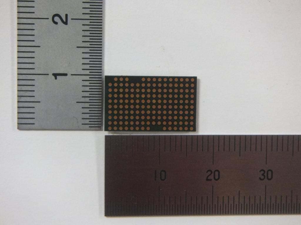
EW4DWMW095A
Jul 10, 2013802.11abgn 2X2 MIMO + BT/BLE RADIO MODULE
Equipment Class
DTS - Digital Transmission System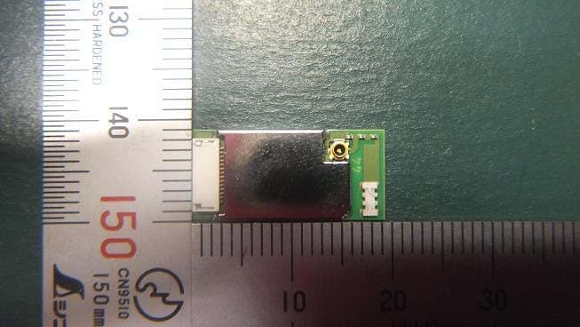
EW4DWMW078
Feb 07, 2013Wireless LAN module
Equipment Class
DTS - Digital Transmission System