EW4DOLAWWireless Game Controller
Mitsumi Electric Co Ltd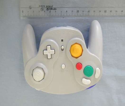
Click to zoom
Application Details
- Equipment Class
- DSS - Part 15 Spread Spectrum Transmitter
- Date of Grant
- May 09, 2002
- Application Purpose
- Original Equipment
- Date of Application
- May 07, 2002
- Equipment Note
- Wireless Game Controller
- Frequency Range
- 2404.80000000 - 2480.00000000
- Company
- Mitsumi Electric Co Ltd
- Country
- Japan
Documents & Files
Document Text
Text extracted from the exhibit documents filed with the FCC. Open a document above to read the original.
External Photos
MITSUMI ELECTRIC CO., LTD. WIRELESS CONTROLLER & RECEIVER for VIDEOGAME FCC ID:EW4DOLAW IC:4250A-DOLAW External Photos Unit : mm
ID Label/Location Info
MITSUMI ELECTRIC CO., LTD. WIRELESS CONTROLLER & RECEIVER for VIDEOGAME FCC ID:EW4DOLAW IC:4250A-DOLAW ID Label
Internal Photos
MITSUMI ELECTRIC CO., LTD. WIRELESS CONTROLLER & RECEIVER for VIDEOGAME FCC ID:EW4DOLAW IC:4250A-DOLAW Internal Photos Connecting Tx module Not connecting Tx module Unit : mm Tx module Tx Antenna
Test Report
Processing Gain TEST REPORT Report No.: Z01C-02080 Issue Date: March 29, 2002 FCC CFR 47, Paragraph 15.247(e) Equipment under test : WIRELESS CONTROLLER & RECEIVER for VIDEOGAME FCC ID : EW4DOLAW Trade Name : NINTENDO GAMECUBE WIRELESS COTROLLER WAVEBIRD Model Number : DOL-004 ZACTA Technology Corporation Yonezawa Testing Center 4149-7 Hachimanpara 5-chome Yonezawa-shi Yamagata 992- 1128 Japan Phone: +81-238-28-2880 Fax: +81-238-28-2888 Scope This report contains the results of the processing gain testing performed on the "NINTENDO GAMECUBE WIRELESS CONTROLLER WAVEBIRD". The tests were carried out in accordance with FCC CFR 47 Part 15, Paragraph 15.247(e). The jamming margin method specified 15.247(e)(2) was used to perform the processing gain testing. FCC97-114, Guidance on Measurements for Direct Sequence Spread Spectrum Systems, was also utilized as a guiding document for performance of the processing gain testing. FCC Requirements The processing gain of direct sequence system shall be at least 10dB. The processing gain shall be determined from the ratio n dB of the signal-to-noise ratio with the system spreading code turned off to the signal-to-noise ratio with the system spreading code turned on, as measured at the demodulated output of the receiver. Test Equipment Agilent Signal Generator, MODEL 8648D, 9kHz-4GHz Anritsu Power Meter, MODEL ML2437A Anritsu Power Sensor, MODEL MA2472A, 10MHz-18GHz Anritsu Data Transmission Analyzer, MODEL MD6420A Anritsu 2-Way Combiner/Splitter, MODEL Z-164A Agilent Step Attenuator, MODEL 8494B/8496B, 1dB step/10dB step Method of Measurement As mentioned in the scope section, the jamming margin method was used. The following drawing titled "Processing Gain - Jamming Test Setup" illustrates a block diagram of the test setup. In this method, a signal generator was stepped in 50kHz increments across the passband of the system. At each point, the level of the signal generator required to produce the recommended Bit Error Rate (BER) was recorded. This level is the jammer level. The output power of the transmitter was also recorded at these same points. This level is the signal level. The jammer to signal ratio (J/S) was then calculated. The worst 20% of the J/S data points were discarded. The lowest remaining J/S ratio was used to calculate the processing gain for each of (S/N)o + Mj + Lsys, where Gp = the processing gain of the system, (S/N)o = signal to noise ratio required for the chosen BER, Mj = J/S ratio, and Lsys = system losses. Note that total system losses in a system, including intentional radiator and receiver, are assumed to be no more than 2dB as specified by the FCC. An ideal signal to noise ratio, also referred to as (S/N)o or (Es/No), of 13.3dB was used as specified by MegaChips when calculating the processing gain when operating at 96kbps. The "NINTENDO GAMECUBE WIRELESS CONTROLLER WAVEBIRD" operates at bit rates 96kbps only. A BER (bit error rate) of 1.0e-4 was used to calculate the processing gain. The data presented in this report is for the all case operation of the EUT. Processing Gain-Jamming Test Setup Transmitter: DOL-004 Signal Generator 2-Way Combiner 2-Way Splitter Power Meter Step Attenuator (1/10dB Step) Receiver DOL-005 Data transmission Analyzer 10dB:Attenuter 6dB:Attenuter Gp (dB)Spec (dB)Gp(dB)Spec (dB) 11.11010.910 10.31010.910 11.11010.510 10.71010.410 11.41010.310 11.11010.510 11.11010.410 11.11010.410 ChannelChannel 19 210 311 412 513 614 715 816 Processing Gain Results summary Test date : March 2,4, 2002 Sample Time: 30 seconds Test pattern: 2E9-1 Receiver Level: -40.0dBm
Test Report
Report No.:Z01C-02079 Page 2 of 36 Table of contents Page 1. Summary of Test Results.....................................................................................................4 2. Equipment description........................................................................................................5 2.1 EUT information..........................................................................................................................5 2.2 Operating channels and frequencies...........................................................................................6 3. Configuration information...................................................................................................7 3.1 Peripheral(s) information (Controller Port 1 connected)............................................................7 3.2 Cable(s) information (Controller Port 1 connected)....................................................................7 3.3 System configuration (Controller Port 1 Connected)................................................................8 3.4 Peripheral(s) information (Controller Port 1,2,3,4 connected)....................................................9 3.5 Cable(s) information (Controller Port 1,2,3,4 connected)............................................................9 3.6 System configuration (Controller Port 1,2,3,4 Connected).....................................................10 3.7 Operating flow.............................................................................................................................11 4. Test Instruments............................................................................................................... 12 5. Test Type and Results........................................................................................................13 5.1. Bandwidth at 6 dB below..........................................................................................................13 5.1.1 Test Procedure [ FCC 15.247(a)(2), IC 5.9.1 ]...........................................................................13 5.1.2 Test Instruments and Measurement Setup................................................................................13 5.1.3. Limit of Bandwidth at 6 dB below.............................................................................................13 5.1.4 Measurement Result...................................................................................................................13 5.1.5 Trace Data...................................................................................................................................13 5.2. Transmitter Output Power.......................................................................................................14 5.2.1 Test Procedure [ FCC 15.247(b)(1), IC 6.2.2(o)(b) ]..................................................................14 5.2.2 Test Instruments and Measurement Setup................................................................................14 5.2.3. Limit of Transmitter Output Power...........................................................................................14 5.2.4 Measurement Results.................................................................................................................14 5.3. Occupied Bandwidth / Band-edge, and Out of Band Emissions..............................................15 5.3.1 Test Procedure [ FCC 15.247 (c), IC 5.9.1, IC6.2.2 (o)(e1) ]......................................................15 5.3.2 Test Instruments and Measurement Setup................................................................................15 5.3.3. Limit of Occupied Bandwidth / Band-edge (at 20 dB below), and Out of Band Emissions.......15 5.3.4 Measurement Results of Occupied Bandwidth / Band-edge....................................................... 15 5.3.5 Measurement Results of Out of Band Emissions.......................................................................16 5.3.6 Trace Data...................................................................................................................................16 5.4. Transmitter Power Spectral Density........................................................................................17 5.4.1. Test Procedure [ FCC 15.247(d), IC 6.2.2(o)(b) ]......................................................................17 ZACTA Technology Corp. FCC ID:EW4DOLAW FCC Certification Rev.3.1 Report No.:Z01C-02079 Page 3 of 36 5.4.2 Test Instruments and Measurement Setup................................................................................17 5.4.3. Limit of Transmitter Power Spectral Density...........................................................................17 5.4.4 Measurement Results.................................................................................................................17 5.4.5 Trace Data...................................................................................................................................17 5.5. Restricted Bands Radiations (9kHz – 25GHz).........................................................................18 5.5.1 Test Procedure [ FCC 15.205/209 , IC 6.2.1/6.3 ]......................................................................18 5.5.2 Test Instruments and Measurement Setup................................................................................18 5.5.3. Limit of Radiated Emission Measurement................................................................................20 5.5.4 Sample of field strength calculation...........................................................................................21 5.5.5 Measurement Results.................................................................................................................21 5.5.6 Data...................................................................................................................…
Text truncated - open the document above for the full version.
Test Setup Photos
MITSUMI ELECTRIC CO., LTD. WIRELESS CONTROLLER & RECEIVER for VIDEOGAME FCC ID:EW4DOLAW The photographs show maximized emission configuration. Radiation Controller Port 1 connection Controller Port 1,2,3,4 connection Connectors The EUT (transmitter) has no interface connector. Receiver Controller Port1 connection Receiver Controller Port1,2,3,4 connection
Contact Information
Applicant
Masashi Tsuchida
Technical Contact
PCTEST Engineering Lab., Inc.Randy Ortanez
[email protected]410-290-6652
6660-B Dobbin Road · Columbia, Maryland · United States
Test Firm
TUV SUD Zacta Ltd.Shin-ichi Abe
Technical Specifications
| # | Rule Parts | Frequency Range | Power Output |
|---|---|---|---|
| 1 | 15C | 2.40 GHz - 2.48 GHz | 340.00 µW |
Other Applications from Mitsumi Electric Co Ltd
EW4C95
May 14, 2015Bluetooth HCI module
Equipment Class
DSS - Part 15 Spread Spectrum Transmitter
EW4DWMW314
Nov 29, 2014Wireless LAN + BT/BLE Module
Equipment Class
DSS - Part 15 Spread Spectrum Transmitter
EW4W092
Oct 28, 2013Wireless LAN Module
Equipment Class
DTS - Digital Transmission System
EW4DWMW095A
Jul 10, 2013802.11abgn 2X2 MIMO + BT/BLE RADIO MODULE
Equipment Class
DTS - Digital Transmission System
EW4DWMW078
Feb 07, 2013Wireless LAN module
Equipment Class
DTS - Digital Transmission System