EW4DWMW042802.11bgn WLAN Module
Mitsumi Electric Co Ltd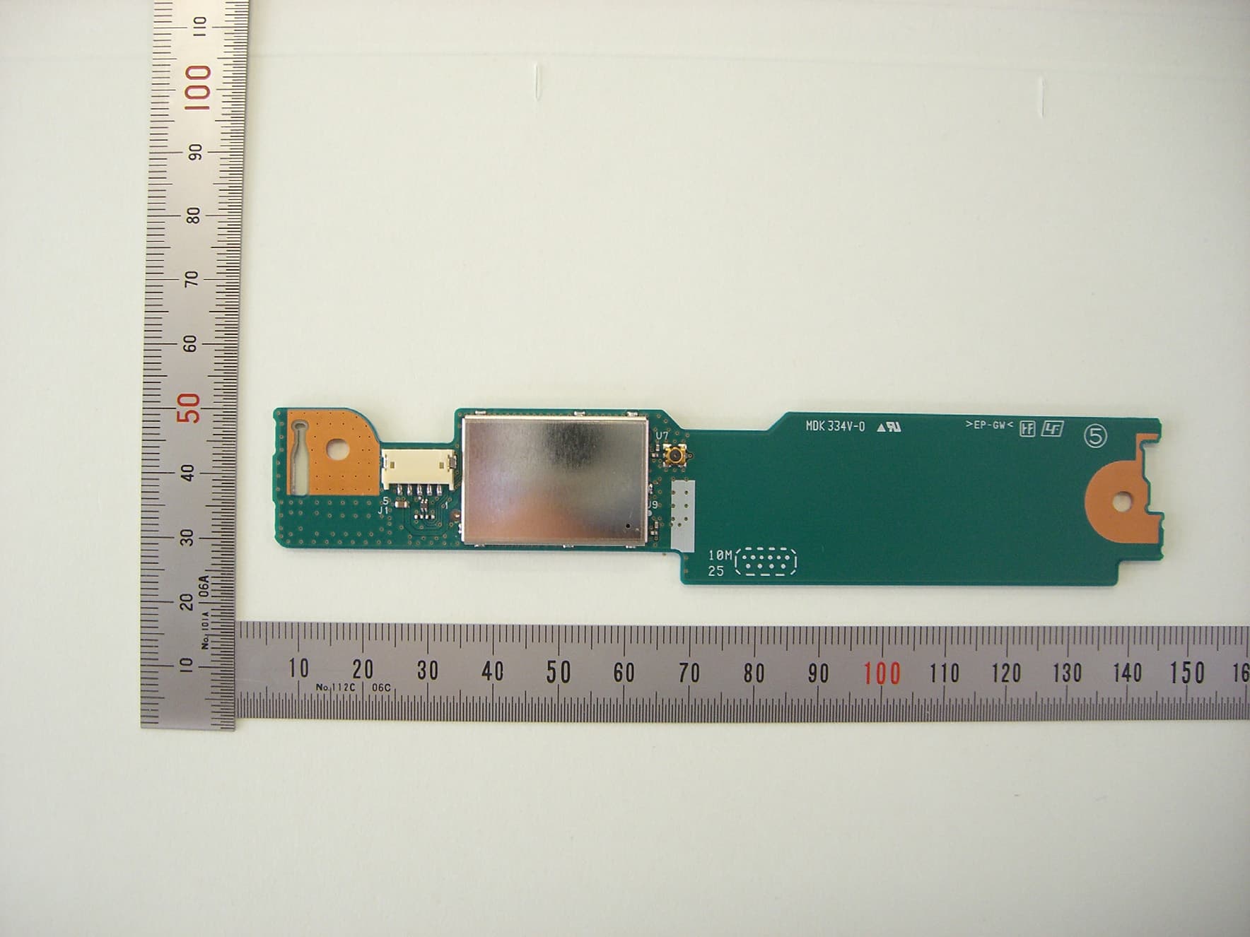
Click to zoom
Application Details
- Equipment Class
- DTS - Digital Transmission System
- Date of Grant
- Sep 07, 2010
- Application Purpose
- Original Equipment
- Date of Application
- Sep 06, 2010
- Equipment Note
- 802.11bgn WLAN Module
- Frequency Range
- 2412.00000000 - 2462.00000000
- Company
- Mitsumi Electric Co Ltd
- Country
- Japan
Documents & Files
Document Text
Text extracted from the exhibit documents filed with the FCC. Open a document above to read the original.
Users Manual
User Manual 802.11bgn WLAN MODULE MODEL DWM-W042 The purpose of this manual is to explain correct way how to integrate module DWM-W042 to the end product. It includes procedures that shall assist you to avoid unforeseen problems. This manual presents information that shows how module and OEM product, where module integrated, complies with regulations in certain regions. Any modifications, not expressly approved by the manufacturer could void the authority to operate in these regions. The 802.11bgn WLAN MODULE, model DWM-W042 has to be installed and used in accordance with the technical description/installation instructions provided by the manufacturer. For detail information concerning type approval of this module (e.g. where this module is already pre-approved) please contact the authorized local distributor or the manufacturer. The system may only be implemented in the configuration that was authorized. Note that any changes or modifications to this equipment not expressly approved by the manufacturer could void the user’s authority to operate this equipment. Regulatory Information Operational Information Wireless Interoperability The end product integrating this module is designed to be interoperable with any wireless LAN product that is based on direct sequence spread spectrum (DSSS) and orthogonal frequency division multiplexing (OFDM) radio technology and to comply with the following standards. ・IEEE Std 802.11b Standard on 2.4GHz Wireless LAN ・IEEE Std 802.11g Standard on 2.4GHz Wireless LAN ・IEEE Std 802.11n Standard on 2.4GHz Wireless LAN Safety The end product integrating this module, like other radio devices, emits radio frequency electromagnetic energy. The level of energy emitted by this device, however, is less than the electromagnetic energy emitted by other wireless devices such as mobile phones. The end product integrating this module operates within the guidelines found in radio frequency safety standards and recommendations. These standards and recommendations reflect the consensus of the scientific community and result from deliberations of panels and committees of scientists who continually review and interpret the extensive research literature. In some situations or environments, the use of the end product integrating this module may be restricted by the proprietor of the building or responsible representatives of the applicable organization. Examples of such situations include the following: ・Using the end product integrating this module onboard airplanes, or ・Using the end product integrating this module in any other environment where the risk of interference with other devices or services is perceived or identified as being harmful. If uncertain of the policy that applies to the use of wireless devices in a specific organization or environment (an airplane, for example), ask for authorization to use the end product integrated into this module before turning it on. USA-Federal Communications Commission (FCC) This equipment has been tested and found to comply with the limits for a Class B digital device, pursuant to Part 15 of FCC Rules. These limits are designed to provide reasonable protection against harmful interference in a residential installation. This equipment generates, uses, and can radiate radio frequency energy. If not installed and used in accordance with the instructions, it may cause harmful interference to radio communications. However, there is no guarantee that interference will not occur in a particular installation. If this equipment does cause harmful interference to radio or television reception, which can be determined by tuning the equipment off and on, the user is encouraged to try and correct the interference by one or more of the following measures: -Reorient or relocate the receiving antenna. -Increase the distance between the equipment and the receiver. -Connect the equipment to outlet on a circuit different from that to which the receiver is connected. -Consult the dealer or an experienced radio/TV technician for help. This device complies with Part 15 of the FCC Rules. Operation is subject to the following two conditions: (1) This device may not cause harmful interference, and (2) This device must accept any interference received, including interference that may cause undesired operation. Any changes or modifications not expressly approved by the party responsible for compliance could void the user’s authority to operate the equipment. Labeling MITSUMI WiFi MODULE DWM-W042 labelled as below. FCC ID: EW4DWMW042 The label with FCC ID is to be placed on the module. If FCC ID is not visible when the module is installed into the system, “Contains FCC ID: EW4DWMW042” shall be placed on the outside of final host system. Caution: Exposure to Radio Frequency Radiation. To comply with FCC RF exposure compliance requirements, a separation distance of at least 20 cm must be maintained between the antenna of this device and all persons. This device must not be co-located or operating in conjunction with any other antenna or transmitter. Canada-Industry Canada (IC) This device complies with RSS 210 of Industry Canada. Operation is subject to the following two conditions: (1) This device may not cause interference, and (2) This device must accept any interference, including interference that may cause undesired operation of this device. L ‘ utilization de ce dispositif est autorisée seulement aux conditions suivantes : (1) il ne doit pas produire de brouillage et (2) l’ utilisateur du dispositif doit étre prêt à accepter tout brouillage radioélectrique reçu, même si ce brouillage est susceptible de compromettre le fomctionnement du dispositif. The term “IC” before the equipment certification number only signifies that the Industry Canada technical specifications were met. To reduce potential radio interference to other users, the antenna type and its gain should be so chosen that the equivalent isotropically radiated power (EIRP) is not more than t…
Text truncated - open the document above for the full version.
Cover Letter(s)
Applicant/Grantee Mitsumi Electric Co., Ltd. FCC ID: EW4DWMW042 Section 15.212 Modular Transmitters Request for Modular Approval Request for Limited Modular Approval Requirements EUT Conditions Comply (Y/N) Single Modular Approval Requirements 1 The radio elements of the modular transmitter must have their own shielding. The physical crystal and tuning capacitors may be located external to the shielded radio elements. The device is equipped with Metal shielding to cover RF section. Refer to external photos Y 2 The modular transmitter must have buffered modulation/data inputs (if such inputs are provided) to ensure that the module will comply with Part 15 requirements under conditions of excessive data rates or over- modulation. All inputs to the device are buffered through logic U4 inputs. Refer to Schematic Diagram. Y 3 The modular transmitter must have its own power supply regulation. The device is equipped with Internal 3.3 V regulator. Refer to Block Diagram. Y 4 The modular transmitter must comply with the antenna and transmission system requirements of Sections 15.203, 15.204(b) and 15.204(c). The antenna must either be permanently attached or employ a “unique” antenna coupler (at all connections between the module and the antenna, including the cable). The “professional installation” provision of Section 15.203 is not applicable to modules but can apply to limited modular approvals under paragraph (b) of this section. The device is equipped with the permanently attached antenna. Any connector isn’t used. Refer to Antenna specification ・ Y 5 The modular transmitter must be tested in a stand-alone configuration, i.e., the module must not be inside another device during testing for compliance with Part 15 requirements. Unless the transmitter module will be battery powered, it must comply with the AC line conducted requirements found in Section 15.207. AC or DC power lines and data input/output lines connected to the module must not contain ferrites, unless they will be marketed with the module (see Section 15.27(a)). The length of these lines shall be the length typical of actual use or, if that length is unknown, at least 10 centimeters to insure that there is no coupling between the case of the module and supporting equipment. Any accessories, peripherals, or support equipment connected to the module during testing shall be unmodified and commercially The device was tested outside of the Laptop PC for full modular approval. Refer to setup photos. Y available (see Section 15.31(i)). 6 The modular transmitter must be equipped with either a permanently affixed label or must be capable of electronically displaying its FCC identification number. (A) If using a permanently affixed label, the modular transmitter must be labeled with its own FCC identification number, and, if the FCC identification number is not visible when the module is installed inside another device, then the outside of the device into which the module is installed must also display a label referring to the enclosed module. This exterior label can use wording such as the following: “Contains Transmitter Module FCC ID: XYZMODEL1” or “Contains FCC ID: XYZMODEL1.” Any similar wording that expresses the same meaning may be used. The Grantee may either provide such a label, an example of which must be included in the application for equipment authorization, or, must provide adequate instructions along with the module which explain this requirement. In the latter case, a copy of these instructions must be included in the application for equipment authorization. (B) If the modular transmitter uses an electronic display of the FCC identification number, the information must be readily accessible and visible on the modular transmitter or on the device in which it is installed. If the module is installed inside another device, then the outside of the device into which the module is installed must display a label referring to the enclosed module. This exterior label can use wording such as the following: “Contains FCC certified transmitter module(s).” Any similar wording that expresses the same meaning may be used. The user manual must include instructions on how to access the electronic display. A copy of these instructions must be included in the application for equipment authorization. The proposed FCC ID label format is to be placed on the module. If FCC ID is not visible when the module is installed into the system, “Contains FCC ID: EW4DWMW042” shall be placed on the outside of final host system. Y 7 The modular transmitter must comply with any specific rules or operating requirements that ordinarily apply to a complete transmitter and the manufacturer must provide adequate instructions along with the module to explain any such requirements. A copy of these instructions must be included in the application for equipment authorization. Refer to “User’s Guide” Exhibit Y 8 The modular transmitter must comply with any applicable RF exposure requirements in its final configuration. The device complies with RF exposure compliance requirement Y A limited modular approval may be granted for single or split modular transmitters that do not comply with all of the above requirements, e.g., shielding, minimum signaling amplitude, buffered modulation/data inputs, or power supply regulation, if the manufacturer can demonstrate by alternative means in the application for equipment authorization that the modular transmitter meets all the applicable Part 15 requirements under the operating conditions in which the transmitter will be used. Limited modular approval also may be granted in those instances where compliance with RF exposure rules is demonstrated only for particular product configurations. The applicant for certification must state how control of the end product into which the module will be installed will be maintained such that full compliance of the end product is always ensured.
External Photos
DWM-W042 External Photo
Internal Photos
DWM-W042 Internal Photo
Test Report
FCC CFR47 PART 15 SUBPART C INDUSTRY CANADA RSS-210 ISSUE 7 CERTIFICATION TEST REPORT FOR 802.11bgn WLAN MODULE MODEL NUMBER: DWM-W042 FCC ID: EW4DWMW042 IC: 4250A-DWMW042 REPORT NUMBER: 10J13370-1 ISSUE DATE: AUGUST 24, 2010 Prepared for MITSUMI ELECTRIC CO., LTD. 1601, SAKAI, ATSUGI-SHI, KANAGAWA, 243-8533, JAPAN Prepared by COMPLIANCE CERTIFICATION SERVICES 47173 BENICIA STREET FREMONT, CA 94538, U.S.A. TEL: (510) 771-1000 FAX: (510) 661-0888 REPORT NO: 10J13370-1 DATE: AUGUST 24, 2010 FCC ID: EW4DWMW042 IC ID: 4250A-DWMW042 Page 2 of 99 COMPLIANCE CERTIFICATION SERVICES FORM NO: CCSUP4701C 47173 BENICIA STREET, FREMONT, CA 94538, USA TEL: (510) 771-1000 FAX: (510) 661-0888 This report shall not be reproduced except in full, without the written approval of CCS. Revision History Rev. Issue Date Revisions Revised By -- 08/24/10 Initial Issue T. Chan REPORT NO: 10J13370-1 DATE: AUGUST 24, 2010 FCC ID: EW4DWMW042 IC ID: 4250A-DWMW042 Page 3 of 99 COMPLIANCE CERTIFICATION SERVICES FORM NO: CCSUP4701C 47173 BENICIA STREET, FREMONT, CA 94538, USA TEL: (510) 771-1000 FAX: (510) 661-0888 This report shall not be reproduced except in full, without the written approval of CCS. TABLE OF CONTENTS 1. ATTESTATION OF TEST RESULTS.................................................................................... 5 2. TEST METHODOLOGY ........................................................................................................ 6 3. FACILITIES AND ACCREDITATION.................................................................................... 6 4. CALIBRATION AND UNCERTAINTY .................................................................................. 6 4.1. MEASURING INSTRUMENT CALIBRATION ............................................................... 6 4.2. SAMPLE CALCULATION.............................................................................................. 6 4.3. MEASUREMENT UNCERTAINTY................................................................................ 6 5. EQUIPMENT UNDER TEST ................................................................................................. 7 5.1. DESCRIPTION OF EUT................................................................................................ 7 5.2. MAXIMUM OUTPUT POWER....................................................................................... 7 5.3. DESCRIPTION OF AVAILABLE ANTENNAS............................................................... 7 5.4. SOFTWARE AND FIRMWARE..................................................................................... 7 5.5. WORST-CASE CONFIGURATION AND MODE .......................................................... 7 5.6. DESCRIPTION OF TEST SETUP................................................................................. 8 6. TEST AND MEASUREMENT EQUIPMENT ....................................................................... 10 7. ANTENNA PORT TEST RESULTS .................................................................................... 11 7.1. 802.11b MODE............................................................................................................ 11 7.1.1. 6 dB BANDWIDTH .............................................................................................. 11 7.1.2. 99% BANDWIDTH .............................................................................................. 14 7.1.3. OUTPUT POWER ............................................................................................... 17 7.1.4. AVERAGE POWER ............................................................................................ 18 7.1.5. POWER SPECTRAL DENSITY .......................................................................... 19 7.1.6. CONDUCTED SPURIOUS EMISSIONS............................................................. 22 7.2. 802.11 g MODE IN THE 2.4 GHz BAND..................................................................... 28 7.2.1. 6 dB BANDWIDTH .............................................................................................. 28 7.2.2. 99% BANDWIDTH .............................................................................................. 31 7.2.3. OUTPUT POWER ............................................................................................... 34 7.2.4. AVERAGE POWER ............................................................................................ 35 7.2.5. POWER SPECTRAL DENSITY .......................................................................... 36 7.2.6. CONDUCTED SPURIOUS EMISSIONS............................................................. 39 7.3. 802.11HT 20 MODE IN THE 2.4 GHz BAND.............................................................. 43 7.3.1. 6 dB BANDWIDTH .............................................................................................. 43 7.3.2. 99% BANDWIDTH .............................................................................................. 46 7.3.3. OUTPUT POWER ............................................................................................... 49 7.3.4. AVERAGE POWER ............................................................................................ 50 7.3.5. POWER SPECTRAL DENSITY .......................................................................... 51 7.3.6. CONDUCTED SPURIOUS EMISSIONS............................................................. 54 8. RADIATED TEST RESULTS .............................................................................................. 58 REPORT NO: 10J13370-1 DATE: AUGUST 24, 2010 FCC ID: EW4DWMW042 IC ID: 4250A-DWMW042 Page 4 of 99 COMPLIANCE CERTIFICATION SERVICES FORM NO: CCSUP4701C 47173 BENICIA STREET, FREMONT, CA 94538, USA TEL: (510) 771-1000 FAX: (510) 661-0888 This report shall not be reproduced except in full, without the written approval of CCS. 8.1. LIMITS AND PROCEDURE ........................................................................................ 58 …
Text truncated - open the document above for the full version.
Test Setup Photos
REPORT NO: 10J13370-1 DATE: AUGUST 24, 2010 FCC ID: EW4DWMW042 IC ID: 4250A-DWMW042 Page 95 of 99 COMPLIANCE CERTIFICATION SERVICES FORM NO: CCSUP4701C 47173 BENICIA STREET, FREMONT, CA 94538, USA TEL: (510) 771-1000 FAX: (510) 661-0888 This report shall not be reproduced except in full, without the written approval of CCS. 11. SETUP PHOTOS ANTENNA PORT CONDUCTED RF MEASUREMENT SETUP ANTENNA PORT CONDUCTED PHOTO REPORT NO: 10J13370-1 DATE: AUGUST 24, 2010 FCC ID: EW4DWMW042 IC ID: 4250A-DWMW042 Page 96 of 99 COMPLIANCE CERTIFICATION SERVICES FORM NO: CCSUP4701C 47173 BENICIA STREET, FREMONT, CA 94538, USA TEL: (510) 771-1000 FAX: (510) 661-0888 This report shall not be reproduced except in full, without the written approval of CCS. RADIATED RF MEASUREMENT SETUP FOR PORTABLE CONFIGURATION X-ORINTATION PHOTOS Z-ORINTATION PHOTOS REPORT NO: 10J13370-1 DATE: AUGUST 24, 2010 FCC ID: EW4DWMW042 IC ID: 4250A-DWMW042 Page 97 of 99 COMPLIANCE CERTIFICATION SERVICES FORM NO: CCSUP4701C 47173 BENICIA STREET, FREMONT, CA 94538, USA TEL: (510) 771-1000 FAX: (510) 661-0888 This report shall not be reproduced except in full, without the written approval of CCS. Z-ORINTATION PHOTOS REPORT NO: 10J13370-1 DATE: AUGUST 24, 2010 FCC ID: EW4DWMW042 IC ID: 4250A-DWMW042 Page 98 of 99 COMPLIANCE CERTIFICATION SERVICES FORM NO: CCSUP4701C 47173 BENICIA STREET, FREMONT, CA 94538, USA TEL: (510) 771-1000 FAX: (510) 661-0888 This report shall not be reproduced except in full, without the written approval of CCS. RADIATED RF MEASUREMENT SETUP RADIATED FRONT PHOTO RADIATED BACK PHOTO REPORT NO: 10J13370-1 DATE: AUGUST 24, 2010 FCC ID: EW4DWMW042 IC ID: 4250A-DWMW042 Page 99 of 99 COMPLIANCE CERTIFICATION SERVICES FORM NO: CCSUP4701C 47173 BENICIA STREET, FREMONT, CA 94538, USA TEL: (510) 771-1000 FAX: (510) 661-0888 This report shall not be reproduced except in full, without the written approval of CCS. POWERLINE CONDUCTED EMISSIONS MEASUREMENT SETUP END OF REPORT LINE CONDUCTED FRONT PHOTO LINE CONDUCTED BACK PHOTO
Contact Information
Applicant
Masashi Tsuchida
Technical Contact
Compliance Certification ServicesThu Chan
[email protected]510-771-1000
47173 Benicia Street · Fremont, California · United States
Test Firm
Compliance Certification ServicesThu Chan
Technical Specifications
| # | Rule Parts | Frequency Range | Power Output |
|---|---|---|---|
| 2 | 15C | 2.41 GHz - 2.46 GHz | 262.42 mW |
Other Applications from Mitsumi Electric Co Ltd
EW4C95
May 14, 2015Bluetooth HCI module
Equipment Class
DSS - Part 15 Spread Spectrum Transmitter
EW4DWMW314
Nov 29, 2014Wireless LAN + BT/BLE Module
Equipment Class
DSS - Part 15 Spread Spectrum Transmitter
EW4W092
Oct 28, 2013Wireless LAN Module
Equipment Class
DTS - Digital Transmission System
EW4DWMW095A
Jul 10, 2013802.11abgn 2X2 MIMO + BT/BLE RADIO MODULE
Equipment Class
DTS - Digital Transmission System
EW4DWMW078
Feb 07, 2013Wireless LAN module
Equipment Class
DTS - Digital Transmission System