EW4DWMW091Wireless LAN ,Bluetooth Combo Module
Mitsumi Electric Co Ltd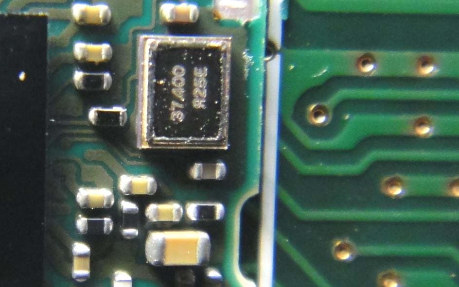
Click to zoom
Application Details
- Equipment Class
- NII - Unlicensed National Information Infrastructure TX
- Date of Grant
- Aug 29, 2012
- Application Purpose
- Original Equipment
- Date of Application
- Aug 29, 2012
- Equipment Note
- Wireless LAN ,Bluetooth Combo Module
- Frequency Range
- 5500.00000000 - 5700.00000000
- Company
- Mitsumi Electric Co Ltd
- Country
- Japan
Documents & Files
Document Text
Text extracted from the exhibit documents filed with the FCC. Open a document above to read the original.
Cover Letter(s)
Applicant/Grantee MITSUMI ELECTRIC CO., LTD. FCC ID: EW4DWMW091 Section 15.212 Modular Transmitters Request for Modular Approval Request for Limited Modular Approval Requirements EUT Conditions Comply (Y/N) Single Modular Approval Requirements 1 The radio elements of the modular transmitter must have their own shielding. The physical crystal and tuning capacitors may be located external to the shielded radio elements. See EUT photos Y 2 The modular transmitter must have buffered modulation/data inputs (if such inputs are provided) to ensure that the module will comply with Part 15 requirements under conditions of excessive data rates or over-modulation. See schematics Y 3 The modular transmitter must have its own power supply regulation. See schematics Y 4 The modular transmitter must comply with the antenna and transmission system requirements of Sections 15.203, 15.204(b) and 15.204(c). The antenna must either be permanently attached or employ a “unique” antenna coupler (at all connections between the module and the antenna, including the cable). The “professional installation” provision of Section 15.203 is not applicable to modules but can apply to limited modular approvals under paragraph (b) of this section. PIFA antenna is used and module will be equipped to the end product for sale, user will not have chance to change the antenna. Y 5 The modular transmitter must be tested in a stand-alone configuration, i.e., the module must not be inside another device during testing for compliance with Part 15 requirements. Unless the transmitter module will be battery powered, it must comply with the AC line conducted requirements found in Section 15.207. AC or DC power lines and data input/output lines connected to the module must not contain ferrites, unless they will be marketed with the module (see Section 15.27(a)). The length of these lines shall be the length typical of actual use or, if that length is unknown, at least 10 centimeters to insure that there is no coupling between the case of the module and supporting See test setup photos Y equipment. Any accessories, peripherals, or support equipment connected to the module during testing shall be unmodified and commercially available (see Section 15.31(i)). 6 The modular transmitter must be equipped with either a permanently affixed label or must be capable of electronically displaying its FCC identification number. (A) If using a permanently affixed label, the modular transmitter must be labeled with its own FCC identification number, and, if the FCC identification number is not visible when the module is installed inside another device, then the outside of the device into which the module is installed must also display a label referring to the enclosed module. This exterior label can use wording such as the following: “Contains Transmitter Module FCC ID: XYZMODEL1” or “Contains FCC ID: XYZMODEL1.” Any similar wording that expresses the same meaning may be used. The Grantee may either provide such a label, an example of which must be included in the application for equipment authorization, or, must provide adequate instructions along with the module which explain this requirement. In the latter case, a copy of these instructions must be included in the application for equipment authorization. (B) If the modular transmitter uses an electronic display of the FCC identification number, the information must be readily accessible and visible on the modular transmitter or on the device in which it is installed. If the module is installed inside another device, then the outside of the device into which the module is installed must display a label referring to the enclosed module. This exterior label can use wording such as the following: “Contains FCC certified transmitter module(s).” Any similar wording that expresses the same meaning may be used. The user manual must include instructions on how to access the electronic display. A copy of these instructions must be included in the application for equipment authorization. See user manual and label format Y 7 The modular transmitter must comply with any specific rules or operating requirements that ordinarily apply to a complete transmitter and the manufacturer must provide adequate instructions along with the module to explain any such requirements. A copy of these instructions must be included in the application for equipment authorization. See user manual Y 8 The modular transmitter must comply with any applicable RF exposure requirements in its final configuration. See user manual Y A limited modular approval may be granted for single or split modular transmitters that do not comply with all of the above requirements, e.g., shielding, minimum signaling amplitude, buffered modulation/data inputs, or power supply regulation, if the manufacturer can demonstrate by alternative means in the application for equipment authorization that the modular transmitter meets all the applicable Part 15 requirements under the operating conditions in which the transmitter will be used. Limited modular approval also may be granted in those instances where compliance with RF exposure rules is demonstrated only for particular product configurations. The applicant for certification must state how control of the end product into which the module will be installed will be maintained such that full compliance of the end product is always ensured.
External Photos
Compliance Certification Services Inc. Report No.: T120702I01 Date of Issue: August 6, 2012 A1 - 1 Total Page: 5 APPENDIX 1 - PHOTOGRAPHS OF EUT EXTERNAL PHOTOGRAPHS OF EUT
Internal Photos
Compliance Certification Services Inc. Report No.: T120702I01 Date of Issue: August 6, 2012 A1 - 2 INTERNAL PHOTOGRAPHS OF EUT Compliance Certification Services Inc. Report No.: T120702I01 Date of Issue: August 6, 2012 A1 - 3 Compliance Certification Services Inc. Report No.: T120702I01 Date of Issue: August 6, 2012 A1 - 4 Antenna Compliance Certification Services Inc. Report No.: T120702I01 Date of Issue: August 6, 2012 A1 - 5
RF Exposure Info
Compliance Certification Services Inc. FCC ID: EW4DWMW091 IC: 4250A-DWMW091 Report No.: T120702I01-RP3 Rev. 00 APPENDIX I RADIO FREQUENCY EXPOSURE LIMIT Systems operating under the provisions of this section shall be operated in a manner that ensures that the public is not exposed to radio frequency energy levels in excess of the Commission's guidelines. See §15.247(i) and §1.1307(b)(1) of this chapter. EUT Specification EUT Wireless LAN ,Bluetooth Comb Module Frequency band (Operating) WLAN: 2.412GHz ~ 2.462GHz WLAN: 5.18GHz ~ 5.32GHz / 5.50GHz ~ 5.70GHz WLAN: 5.745GHz ~ 5.825GHz Bluetooth: 2.402GHz ~ 2.480 GHz Device category Portable (<20cm separation) Mobile (>20cm separation) Exposure classification Occupational/Controlled exposure (S = 5mW/cm2) General Population/Uncontrolled exposure (S=1mW/cm2) Antenna diversity Single antenna Multiple antennas Tx diversity Rx diversity Tx/Rx diversity Max. output power 3.14 dBm (2.06mW) Antenna gain (Max) 1.98 dBi (Numeric gain: 1.58) Evaluation applied MPE Evaluation* SAR Evaluation N/A Remark: The maximum output power is 3.14 dBm (2.06mW) at 2480MHz (with 1.58 numeric antenna gain.) TEST RESULTS No non-compliance noted. MPE EVALUATION No non-compliance noted. Compliance Certification Services Inc. FCC ID: EW4DWMW091 IC: 4250A-DWMW091 Report No.: T120702I01-RP3 Rev. 00 Calculation Given d GP E ×× = 30 & 3770 2 E S = Where E = Field strength in Volts / meter P = Power in Watts G = Numeric antenna gain d = Distance in meters S = Power density in milliwatts / square centimeter Combining equations and re-arranging the terms to express the distance as a function of the remaining variables yields: 2 3770 30 d GP S ×× = Changing to units of mW and cm, using: P (mW) = P (W) / 1000 and d (cm) = d(m) / 100 Yields () () 2 2 0796.0 100/3770 1000/30 d GP d GP S × ×= × ×× = Equation 1 Where d = Distance in cm P = Power in mW G = Numeric antenna gain S = Power density in mW / cm 2 Maximum Permissible Exposure EUT output power = 2.06mW Numeric Antenna gain = 1.58 Substituting the MPE safe distance using d = 20 cm into Equation 1: Yields GPS××=000199.0 Where P = Power in mW G = Numeric antenna gain S = Power density in mW / cm 2 Æ Power density = 0.000647 mW / cm 2 (For mobile or fixed location transmitters, the maximum power density is 1.0 mW/cm 2 even if the calculation indicates that the power density would be larger.) Compliance Certification Services Inc. FCC ID: EW4DWMW091 IC: 4250A-DWMW091 Report No.: T120702I01-RP2 Rev.00 APPENDIX I RADIO FREQUENCY EXPOSURE LIMIT According to §15.247(i), systems operating under the provisions of this section shall be operated in a manner that ensures that the public is not exposed to radio frequency energy levels in excess of the Commission's guidelines. See § 1.1307(b)(1) of this chapter. According to RSS-Gen §5.5, before equipment certification is granted, the applicable requirements of RSS-102 shall be met. EUT Specification EUT Wireless LAN ,Bluetooth Comb Module Frequency band (Operating) WLAN: 2.412GHz ~ 2.462GHz WLAN: 5.18GHz ~ 5.32GHz / 5.50GHz ~ 5.70GHz WLAN: 5.745GHz ~ 5.825GHz Others: Bluetooth: 2.402GHz ~ 2.480GHz Device category Portable (<20cm separation) Mobile (>20cm separation) Others __________________________ Exposure classification Occupational/Controlled exposure (S = 5mW/cm 2 ) General Population/Uncontrolled exposure (S=1mW/cm 2 ) Antenna diversity Single antenna Multiple antennas Tx diversity Rx diversity Tx/Rx diversity Max. output power 9.80dBm (9.54 mW) Antenna gain (Max) 1.98 dBi (Numeric gain: 1.58) Evaluation applied MPE Evaluation* SAR Evaluation N/A Remark: The maximum output power is 9.80 dBm (9.54 mW) at 2441MHz (with 1.58 numeric antenna gain.) TEST RESULTS No non-compliance noted. (SAR evaluation is not required for the PORTABLE device while its maximum output power is lower than the general population low threshold: 60/f (GHz) =60/2.441=24.58mW) Compliance Certification Services Inc. FCC ID: EW4DWMW091 IC: 4250A-DWMW091 Report No.: T120702I01-RP2 Rev.00 Calculation Given d GP E ×× = 30 & 3770 2 E S= Where E = Field strength in Volts / meter P = Power in Watts G = Numeric antenna gain d = Distance in meters S = Power density in milliwatts / square centimeter Combining equations and re-arranging the terms to express the distance as a function of the remaining variables yields: 2 3770 30 d GP S ×× = Chainging to units of mW and cm, using: P (mW) = P (W) / 1000 and d (cm) = d(m) / 100 Yields () () 2 2 0796.0 100/3770 1000/30 d GP d GP S × ×= × ×× = Equation 1 Where d = Distance in cm P = Power in mW G = Numeric antenna gain S = Power density in mW / cm 2 Maximum Permissible Exposure EUT output power = 9.54 mW Numeric Antenna gain = 1.58 Substituting the MPE safe distance using d = 20 cm into Equation 1: Yields GPS××=000199.0 Where P = Power in mW G = Numeric antenna gain S = Power density in mW / cm 2 Æ Power density = 0.0029 mW / cm2 (For mobile or fixed location transmitters, the maximum power density is 1.0 mW/cm 2 even if the calculation indicates that the power density would be larger.) Compliance Certification Services Inc. FCC ID: EW4DWMW091 IC: 4250A-DWMW091 Report No.: T120702I01-RP1 Rev. 00 APPENDIX I RADIO FREQUENCY EXPOSURE LIMIT According to §15.247(i), systems operating under the provisions of this section shall be operated in a manner that ensures that the public is not exposed to radio frequency energy levels in excess of the Commission's guidelines. See § 1.1307(b)(1) of this chapter. According to RSS-Gen §5.5, before equipment certification is granted, the applicable requirements of RSS-102 shall be met. EUT Specification EUT Wireless LAN ,Bluetooth Comb Module Frequency band (Operating) WLAN: 2.412GHz ~ 2.462GHz WLAN: 5.18GHz ~ 5.32GHz / 5.50GHz ~ 5.70GHz WLAN: 5.745GHz ~ 5.825GHz Others Device category Portable (<20cm separation) Mobile (>20cm separation) Others Exposure classification Occupational/Controlled exposure (S = 5mW/cm 2 ) General Population/Uncontrolled ex…
Text truncated - open the document above for the full version.
Test Report
Compliance Certification Services Inc. FCC ID: EW4DWMW091 IC: 4250A-DWMW091 Report No.: T120702I01-RP4 Note: This report shall not be reproduced except in full, without the written approval of Compliance Certification Services Inc. This document may be altered or revised by Compliance Certification Services Inc. personnel only, and shall be noted in the revision section of the document. Page 1 Total Page: 166 Rev. 00 FCC 47 CFR PART 15 SUBPART E & INDUSTRY CANADA RSS-210 TEST REPORT For Wireless LAN ,Bluetooth Combo Module Model: DWM-W091 Trade Name: MITSUMI Issued to MITSUMI ELECTRIC CO.,LTD. 1601,SAKAI,ATSUGI-SHI,KANAGAWA, 243-8533 JAPAN Issued by Compliance Certification Services Inc. No.11, Wu-Gong 6th Rd., Wugu Industrial Park, New Taipei City 248, Taiwan (R.O.C.) http://www.ccsrf.com [email protected] Issued Date: August 20, 2012 Compliance Certification Services Inc. FCC ID: EW4DWMW091 IC: 4250A-DWMW091 Report No.: T120702I01-RP4 Page 2 Rev. 00 Revision History Rev. Issue Date Revisions Effect Page Revised By 00 August 20, 2012 Initial Issue ALL Eunice Shen Compliance Certification Services Inc. FCC ID: EW4DWMW091 IC: 4250A-DWMW091 Report No.: T120702I01-RP4 Page 3 Rev. 00 TABLE OF CONTENTS 1. TEST RESULT CERTIFICATION ............................................................................................. 4 2. EUT DESCRIPTION .................................................................................................................... 5 3. TEST METHODOLOGY ............................................................................................................. 7 3.1 EUT CONFIGURATION ................................................................................................... 7 3.2 EUT EXERCISE .............................................................................................................. 7 3.3 GENERAL TEST PROCEDURES ........................................................................................ 7 3.4 FCC PART 15.205 RESTRICTED BANDS OF OPERATIONS ................................... 8 3.5 DESCRIPTION OF TEST MODES ....................................................................................... 9 4. INSTRUMENT CALIBRATION ............................................................................................... 10 4.1 MEASURING INSTRUMENT CALIBRATION ............................................................... 10 4.2 MEASUREMENT EQUIPMENT USED ................................................................. 10 4.3 MEASUREMENT UNCERTAINTY ....................................................................... 11 5. FACILITIES AND ACCREDITATIONS ................................................................................. 12 5.1 FACILITIES ................................................................................................................. 12 5.2 EQUIPMENT ................................................................................................................ 12 5.3 LABORATORY ACCREDITATIONS AND LISTING ............................................................ 12 5.4 TABLE OF ACCREDITATIONS AND LISTINGS ................................................................ 13 6. SETUP OF EQUIPMENT UNDER TEST ................................................................................ 14 6.1 SETUP CONFIGURATION OF EUT .................................................................................. 14 6.2 SUPPORT EQUIPMENT ................................................................................................. 14 7. FCC PART 15 REQUIREMENTS & RSS 210 REQUIREMENTS .................................... 15 7.1 DUTY CYCLE .............................................................................................................. 15 7.2 99% BANDWIDTH ....................................................................................................... 17 7.3 26 DB EMISSION BANDWIDTH ..................................................................................... 28 7.4 MAXIMUM CONDUCTED OUTPUT POWER .................................................................... 39 7.5 BAND EDGES MEASUREMENT .......................................................................... 53 7.6 PEAK POWER SPECTRAL DENSITY ............................................................................... 62 7.7 PEAK EXCURSION ....................................................................................................... 74 7.8 RADIATED UNDESIRABLE EMISSION............................................................................ 86 7.9 CONDUCTED UNDESIRABLE EMISSION ...................................................................... 109 7.10 POWERLINE CONDUCTED EMISSIONS ........................................................................ 119 7.11 FREQUENCY STABILITY ............................................................................................ 122 7.12 DYNAMIC FREQUENCY SELECTION .............................................................. 135 APPENDIX I RADIO FREQUENCY EXPOSURE ..................................................................... 160 APPENDIX 2 PHOTOGRAPHS OF TEST SETUP ..................................................................... 163 APPENDIX 1 - PHOTOGRAPHS OF EUT Compliance Certification Services Inc. FCC ID: EW4DWMW091 IC: 4250A-DWMW091 Report No.: T120702I01-RP4 Page 4 Rev. 00 1. TEST RESULT CERTIFICATION Applicant: MITSUMI ELECTRIC CO.,LTD. 1601,SAKAI,ATSUGI-SHI,KANAGAWA, 243-8533 JAPAN Manufacturer: MITSUMI ELECTRIC CO.,LTD. 1601,SAKAI,ATSUGI-SHI,KANAGAWA, 243-8533 JAPAN Equipment Under Test: Wireless LAN, Bluetooth Combo Module Tr a d e N a m e : MITSUMI Model: DWM-W091 Date of Test: July 21 ~ August 18, 2008 APPLICABLE STANDARDS STANDARD TEST RESULT FCC 47 CFR Part 15 Subpart E & Industry Canada RSS-210 Issue 8 Annex 9 Industry Canada RSS-GEN Issue 3 No non-compliance noted We hereby certify that: Compliance Certification Services Inc. test…
Text truncated - open the document above for the full version.
Test Setup Photos
Compliance Certification Services Inc. FCC ID: EW4DWMW091 IC: 4250A-DWMW091 Report No.: T120702I01-RP4 Page 163 Rev. 00 APPENDIX 2 PHOTOGRAPHS OF TEST SETUP Conducted Emission Set Up Photo Compliance Certification Services Inc. FCC ID: EW4DWMW091 IC: 4250A-DWMW091 Report No.: T120702I01-RP4 Page 164 Rev. 00 Radiated Emission Set up Photos Compliance Certification Services Inc. FCC ID: EW4DWMW091 IC: 4250A-DWMW091 Report No.: T120702I01-RP4 Page 165 Rev. 00 Powerline Conducted Emissions Setup Photos
Contact Information
Applicant
Masashi Tsuchida
Test Firm
Compliance Certification Services Inc.Hank Lee
Technical Specifications
| # | Rule Parts | Frequency Range | Power Output |
|---|---|---|---|
| 3 | 15E | 5.50 GHz - 5.70 GHz | 14.00 mW |
Other Applications from Mitsumi Electric Co Ltd
EW4C95
May 14, 2015Bluetooth HCI module
Equipment Class
DSS - Part 15 Spread Spectrum Transmitter
EW4DWMW314
Nov 29, 2014Wireless LAN + BT/BLE Module
Equipment Class
DSS - Part 15 Spread Spectrum Transmitter
EW4W092
Oct 28, 2013Wireless LAN Module
Equipment Class
DTS - Digital Transmission System
EW4DWMW095A
Jul 10, 2013802.11abgn 2X2 MIMO + BT/BLE RADIO MODULE
Equipment Class
DTS - Digital Transmission System
EW4DWMW078
Feb 07, 2013Wireless LAN module
Equipment Class
DTS - Digital Transmission System