EZZ5PI001103One-Way Signal Booster Amplifier
Bird Technologies Group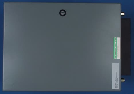
Click to zoom
Application Details
- Equipment Class
- AMP - Amplifier
- Date of Grant
- Feb 26, 2001
- Application Purpose
- Original Equipment
- Date of Application
- Feb 26, 2001
- Equipment Note
- One-Way Signal Booster Amplifier
- Frequency Range
- 929.00000000 - 932.00000000
- Company
- Bird Technologies Group
- Country
- United States
Documents & Files
Document Text
Text extracted from the exhibit documents filed with the FCC. Open a document above to read the original.
Users Manual
EXHIBIT 2 PAGE 1 OF 17 TX RX Systems Inc. Manual 7-9257 (version 1) 11/03/00 Page 1 7-9257-1 Installation and Setup Manual for the One-way Signal Booster System Model Number 60-96-00400-G1 First Printing: November 2000 Version NumberVersion Date 111/03/00 82NCB Part No. Copyright (c) 2000 TX Rx Systems, Inc. EXHIBIT 2 PAGE 2 OF 17 TX RX Systems Inc. Manual 7-9257 (version 1) 11/03/00 Page 2 WARRANTY This warranty applies for one year from shipping date. TX RX SYSTEMS INC. warrants its products to be free from defects in material and workman- ship at the time of shipment. Our obligation under warranty is limited to replacement or repair at our option, of any such products (with the exception of tubes) which shall have been defective at the time of manufacture. TX RX SYSTEMS INC. reserves the right to replace with merchandise of equal performance although not identical in every way to that originally sold. TX RX SYS- TEMS INC. is not liable for damage caused by lightning or other natural disasters. No product will be accepted for repair or replacement without our prior written approval. All Shipping charges on returned products must be prepaid by the purchaser. TX RX SYSTEMS INC. shall in no event be liable for consequential damages, installation costs or expenses of any nature resulting from the purchase or use of products, whether or not they are used in accordance with instructions. This warranty is in lieu of all other warranties, either expressed or implied, including any implied warranty of merchantability or of fitness. No representative is authorized to assume for TX RX SYSTEMS INC. any other liability or warranty than set forth above in connec- tion with our products or services. EXHIBIT 2 PAGE 3 OF 17 TX RX Systems Inc. Manual 7-9257 (version 1) 11/03/00 Page 3 Table of Contents General Description4 Note About Output Power Rating5 Installation Cautionary Note Pre-RF Connection Tests6 Test Equipment Antenna Isolation7 Procedure for Measuring Antenna Isolation Increasing Isolation Input Signal Levels Procedure for Measuring Input Signal Levels8 Reduction of Incoming Signal Strength9 Setting Signal Booster Gain Gain Reduction Methods Bypassing Amplifier Stages Operation Performance Survey10 Maintenance and Repair Detailed Subassembly Descriptions11 Preselector Assembly 3-14478 OLC Assembly 3-941712 Pre-Amplifier 3-1143213 First Driver Amplifier 3-1143214 Second Driver Amplifier3-11795 Power Amplifier 3-3948 illustrations & Tables Figure 1Inside view of the Model 60-96-00400-G14 Figure 2Measuring Antenna Isolation6 Figure 3Measuring Input Signal Levels8 Figure 4Measuring Signal Booster Gain10 Figure 5Surveying Performance11 Figure 6OLC Assembly 3-941712 EXHIBIT 2 PAGE 4 OF 17 TX RX Systems Inc. Manual 7-9257 (version 1) 11/03/00 Page 4 GENERAL DESCRIPTION Signal boosters extend radio coverage into areas where abrupt propagation losses prevent reliable communication. This system receives an RF sig- nal, raises its power level, and couples it to an antenna or leaky (radiating) coaxial cable system so that it can be re-radiated. No frequency transla- tion (conversion) occurs with this device. The one-way signal booster model 60-96-00400- G1 (shown in figure 1) is a broadband, bidirectional single branch system which passes frequencies from 929 to 932 MHz. The system covers a 3 MHz passband width (factory set) and uses linear RF active amplifiers, filters, and DC power sources to adequately boost and re-radiate the passband sig- nals. The output level of any signal passing through a signal booster is determined by the systems gain specification. All signals passing through a prop- erly operating signal booster are amplified by the Figure 1: Inside view of the model 60-96-00400-G1 one-way signal booster system. Output Por t Door Input Preselector 3-14478 3 and 6 dB Fixed Attenuator Pads OLC Assembly AC Receptacle Power Supply 3-14915 Output Preselector 3-14478 1 and 4 Stage Amplifier 3-11432 Input Port 3 Watt Amplifier 3-11795 Heatsink 6 Watt Amplifier 3-3948 3-9417 EXHIBIT 2 PAGE 5 OF 17 TX RX Systems Inc. Manual 7-9257 (version 1) 11/03/00 Page 5 same amount but will come out at power levels that are related to their respective input level by the gain specification. Signal leveling is not an intended function of a signal booster. Amplifier stages used in this signal booster system may be damaged by excessively strong input signal levels. The system is equipped with Output Leveling Cir- cuitry (OLC) to protect the amplifiers and reduce spurious signals. It is interesting to note that the total power for the multicarrier condition is always less than the maximum single carrier rating. As the number of carriers increases, the difference between the single carrier maximum and the total power of all carriers grows even greater. Linear power amplifiers (Class-A operation) are used in this application in contrast to the highly effi- cient Class-C power amplifiers used in the output stages of most FM land mobile transmitters. Linear amplifiers are biased for a relatively high continu- ous DC current drain that does not change with changing RF drive levels. Class-A amplifiers gener- ally have the lowest efficiency of the various ampli- fier types, typically in the range of 25 - 33%. Their biggest advantage is faithful reproduction of the input waveform which results in the lowest levels of intermodulation distortion products (IM) of all the classes of amplifiers. The generation of IM distor- tion is a serious design consideration when two or more channels are simultaneously present in the same amplifier stage. Filtering is used at the input and output of the sig- nal path to help suppress any IM products that may be inadvertently generated. Signals that exceed the maximum input rating may either damage the signal booster or cause it to generate intermodula- tion products that exceed the maximum allowed by the FCC or other regulatory agency. Note About Output Power Ratings A single maximum output…
Text truncated - open the document above for the full version.
Cover Letter(s)
S:\TimcoOffice\ReportTemplate\probonholdemail.doc TIMCO TIMCOTIMCO TIMCO ENGINEERING INC. 849 NW State Road 45 Newberry, Florida 32669 http://www.timcoengr.com 888.472.2424 F 352.472.2030 email: tei@t imcoengr.com 21 February 2001 FCC SUBJECT: TX RX SYSTEMS INC. FCC ID:EZZ5PI001103 TO WHOM IT MAY CONCERN, Based on 1.1307 & 2.1091(c) this EUT is excluded from routine RF exposure evaluation and best falls into the category I for fixed transmitters identified in table 1 of 1.1307 as a Pico-base station, subject to Section B of Review & Approval Procedures. Sincerely, Sid Sanders
ID Label/Location Info
EXHIBIT 1 PAGE 1 OF 1 TX RX SYSTEMS, INC. ANGOLA, NY 14006 EVALUATION FOR FCC TEST 60-96-00400-G1 TX RX SYSTEMS, INC. ANGOLA, NY 14006 FCC ID: EZZ5PI001103 2.25" 4.375" Model No. Label FCC ID Label FRONT DOOR OF CABINET TX RX SYSTEMS, INC. ANGOLA, NY 14006 FCC ID: EZZ5PI001103 Identification Label Location Sketch Proposed Identification Label For the One-Way Signal Booster System Model Number 60-96-00400-G1
Operational Description
OPERATIONAL DESCRIPTION The Model 60-96-00400-G1 is a one-way broadband repeater amplifier intended for repeater application in landmobile communication systems. It includes multiple linear amplifiers with cavity resonators as selective elements. The system is operated from a 117 Vac power supply which provides 21 volts dc to the amplifiers.
Parts List/Tune Up Info
TX RX Systems Inc. Manual 7-9257-1 (addendum) 01/12/01 Page 1 WHEN NEEDED There are two tunable subassemblies within the system including the preselector filters and the amplifiers. Both the preselectors and amplifiers are pre-tuned at the factory and under normal condi- tions do not require tuning. Re-tuning the filters to their original frequencies may be required if a filter is being repaired or replaced. The amplifier tuning procedure needs to be done whenever the RF tran- sistors and/or the matching network components are replaced. The procedures described in this addendum are designed as field alignments for the model 60-96- 004000-G1 One-Way Signal Booster. All steps should be carried out in a step-by-step fashion and all work should be performed by a qualified elec- tronics technician. FILTERS Combline preselector filters provide the input and output selectivity for the system. These are 6 sec- tion bandpass filters which have a carefully shaped response curve that passes a number of contigu- ous communication channels. Both the input and output filter have a factory set bandwidth of 3 MHz. The preselector filters are factory tuned and do not normally need adjustment unless they are damaged or replaced. These devices will stay properly tuned indefinitely unless they have been physically damaged or are tampered with. Input/Output Filters (3-14478) Tuning the filters is a matter of obtaining reason- ably low insertion loss and a return loss of -15 dB or better at the specified frequencies. This may be done in the field when adequate test equipment is available. Required Test Equipment A two channel network analyzer that simulta- neously displays both transmission and reflection is best for properly tuning a preselector. However, a single channel tracking generator/spectrum ana- lyzer combination may be adequate but will be a bit more cumbersome since return loss is not simulta- neously displayed along with insertion loss. For best results a return loss bridge is also required when using a tracking generator/spectrum ana- lyzer. Skill and experience are needed and the per- sonnel doing the work should be thoroughly familiar with the use of the test equipment. Figures 1 and 3 illustrate the use of an IFR A-7550 spec- trum analyzer/tracking generator combination for filter tuning. Figures 2A and 2B show the preselec- tor response curves displayed on a network ana- lyzer. Listed below is a typical combination of equipment: 1) IFR A-7550 Spectrum Analyzer / Tracking Gen- erator combination. 2) Eagle RLB150N3 Return Loss Bridge or equiv- alent (35 dB directivity). 3) Double shielded coaxial cable test leads (RG142 B\U or RG223/U). 4) 50 Ohm load with at least -35 dB return loss (1.10 : 1 VSWR). JFW Industries model 50T- 007 or equivalent. Analyzer Input Generate Output +30 +40 +20 +10 0 -10 -20 -30 -40 6 Section Combline Bandpass Filter Figure 1: Tuning a combline filter. Alignment Procedures for the Model 60-96-00400-G1 One-Way Signal Booster System TX RX Systems Inc. Manual 7-9257-1 (addendum) 01/12/01 Page 2 Equivalent equipment but from other manufactur- ers should yield acceptable results. Filter Tuning The following steps are an outline of the general procedure: 1) Connect the test equipment to the filter assem- bly as shown in figure 1. 2) Set the analyzer to the desired center fre- quency and necessary bandwidth. 3) Loosen the tuning rod locking nuts. 4) If the preselector is severely out of tune, set the analyzer for a 10 dB / division vertical scale on the transmission channel and alternately adjust the tuning rods in pairs working from the center to the end rods for maximum signal at the cen- ter frequency. 5) Repeat step 4 tuning to maximize the signal at the center frequency. The response should start to take on the desired shape and symmetry as shown in figures 2A (10 MHz per/division) and 2B (2 MHz per division). 6) Setup the analyzer for 1 dB per division (2 dB per division when using a tracking generator) and re-adjust the rods in the same fashion for the response with minimum insertion loss at the pass frequency or across the desired pass- band. 7) Connect the equipment as shown in figure 3. Make sure that the return loss curve provides adequate performance (better than -15 dB) over the range and is relatively symmetrical. Fine adjust the tuning rods to adjust symmetry. 8) Repeat steps 6 and 7 until acceptable insertion and return loss are obtained. 9) Lock all tuning rods after the desired response is obtained. Note that a slight dissymmetry in either the transmission or reflection response may be unavoidable. Figure 2A: Preselector response curve shown at 10 MHz per/division. Figure 2B: Preselector response curve shown at 2 Mhz per/division (expanded passband). TX RX Systems Inc. Manual 7-9257-1 (addendum) 01/12/01 Page 3 AMPLIFIERS The amplifier assemblies use bi-polar transistors operating as class A linear amplifiers with varying RF output power capability. They offer a good com- promise between low noise figure and low levels of intermodulation distortion. In addition, these ampli- fiers use narrow band impedance matching cir- cuitry which offers significant improvements in noise figure compared to broadband designs. How- ever, narrowband circuits necessitate having to tune the matching networks to obtain the best per- formance. Each amplifier (see figure 4) uses a bias regulator circuit to keep the RF transistor biased for constant collector current with changes in temperature. The collector current remains constant when these amplifiers are running properly. The actual value of bias current will be different for the different types of amplifiers but can also vary slightly if the power supply voltage varies. Note: The 400 milliwatt amplifiers (part #3-7718) are interconnected with short lengths of double shielded coaxial cable for the RF interconnection. The individual stages are mounted on a common bracket with a DC distribution wire running inter- nally between…
Text truncated - open the document above for the full version.
Schematics
TX RX Systems Inc. Manual 7-9257-1 (addendum) 01/12/01 Page 1 WHEN NEEDED There are two tunable subassemblies within the system including the preselector filters and the amplifiers. Both the preselectors and amplifiers are pre-tuned at the factory and under normal condi- tions do not require tuning. Re-tuning the filters to their original frequencies may be required if a filter is being repaired or replaced. The amplifier tuning procedure needs to be done whenever the RF tran- sistors and/or the matching network components are replaced. The procedures described in this addendum are designed as field alignments for the model 60-96- 004000-G1 One-Way Signal Booster. All steps should be carried out in a step-by-step fashion and all work should be performed by a qualified elec- tronics technician. FILTERS Combline preselector filters provide the input and output selectivity for the system. These are 6 sec- tion bandpass filters which have a carefully shaped response curve that passes a number of contigu- ous communication channels. Both the input and output filter have a factory set bandwidth of 3 MHz. The preselector filters are factory tuned and do not normally need adjustment unless they are damaged or replaced. These devices will stay properly tuned indefinitely unless they have been physically damaged or are tampered with. Input/Output Filters (3-14478) Tuning the filters is a matter of obtaining reason- ably low insertion loss and a return loss of -15 dB or better at the specified frequencies. This may be done in the field when adequate test equipment is available. Required Test Equipment A two channel network analyzer that simulta- neously displays both transmission and reflection is best for properly tuning a preselector. However, a single channel tracking generator/spectrum ana- lyzer combination may be adequate but will be a bit more cumbersome since return loss is not simulta- neously displayed along with insertion loss. For best results a return loss bridge is also required when using a tracking generator/spectrum ana- lyzer. Skill and experience are needed and the per- sonnel doing the work should be thoroughly familiar with the use of the test equipment. Figures 1 and 3 illustrate the use of an IFR A-7550 spec- trum analyzer/tracking generator combination for filter tuning. Figures 2A and 2B show the preselec- tor response curves displayed on a network ana- lyzer. Listed below is a typical combination of equipment: 1) IFR A-7550 Spectrum Analyzer / Tracking Gen- erator combination. 2) Eagle RLB150N3 Return Loss Bridge or equiv- alent (35 dB directivity). 3) Double shielded coaxial cable test leads (RG142 B\U or RG223/U). 4) 50 Ohm load with at least -35 dB return loss (1.10 : 1 VSWR). JFW Industries model 50T- 007 or equivalent. Analyzer Input Generate Output +30 +40 +20 +10 0 -10 -20 -30 -40 6 Section Combline Bandpass Filter Figure 1: Tuning a combline filter. Alignment Procedures for the Model 60-96-00400-G1 One-Way Signal Booster System TX RX Systems Inc. Manual 7-9257-1 (addendum) 01/12/01 Page 2 Equivalent equipment but from other manufactur- ers should yield acceptable results. Filter Tuning The following steps are an outline of the general procedure: 1) Connect the test equipment to the filter assem- bly as shown in figure 1. 2) Set the analyzer to the desired center fre- quency and necessary bandwidth. 3) Loosen the tuning rod locking nuts. 4) If the preselector is severely out of tune, set the analyzer for a 10 dB / division vertical scale on the transmission channel and alternately adjust the tuning rods in pairs working from the center to the end rods for maximum signal at the cen- ter frequency. 5) Repeat step 4 tuning to maximize the signal at the center frequency. The response should start to take on the desired shape and symmetry as shown in figures 2A (10 MHz per/division) and 2B (2 MHz per division). 6) Setup the analyzer for 1 dB per division (2 dB per division when using a tracking generator) and re-adjust the rods in the same fashion for the response with minimum insertion loss at the pass frequency or across the desired pass- band. 7) Connect the equipment as shown in figure 3. Make sure that the return loss curve provides adequate performance (better than -15 dB) over the range and is relatively symmetrical. Fine adjust the tuning rods to adjust symmetry. 8) Repeat steps 6 and 7 until acceptable insertion and return loss are obtained. 9) Lock all tuning rods after the desired response is obtained. Note that a slight dissymmetry in either the transmission or reflection response may be unavoidable. Figure 2A: Preselector response curve shown at 10 MHz per/division. Figure 2B: Preselector response curve shown at 2 Mhz per/division (expanded passband). TX RX Systems Inc. Manual 7-9257-1 (addendum) 01/12/01 Page 3 AMPLIFIERS The amplifier assemblies use bi-polar transistors operating as class A linear amplifiers with varying RF output power capability. They offer a good com- promise between low noise figure and low levels of intermodulation distortion. In addition, these ampli- fiers use narrow band impedance matching cir- cuitry which offers significant improvements in noise figure compared to broadband designs. How- ever, narrowband circuits necessitate having to tune the matching networks to obtain the best per- formance. Each amplifier (see figure 4) uses a bias regulator circuit to keep the RF transistor biased for constant collector current with changes in temperature. The collector current remains constant when these amplifiers are running properly. The actual value of bias current will be different for the different types of amplifiers but can also vary slightly if the power supply voltage varies. Note: The 400 milliwatt amplifiers (part #3-7718) are interconnected with short lengths of double shielded coaxial cable for the RF interconnection. The individual stages are mounted on a common bracket with a DC distribution wire running inter- nally between…
Text truncated - open the document above for the full version.
Test Report
ENGINEERING STATEMENT IN REGARD TO MEASUREMENTS OF TX RX SYSTEMS INC. Model No. 60-96-00400-G1 One-Way Broadband Repeater Amplifier FCC ID: EZZ5PI001103 1.0 Introduction Hyak Laboratories, Inc. has been authorized to perform measurements on the TX RX Systems Inc. Model 60-96-00400-G1 to determine compliance with Part 2 of the FCC Rules. The Model 60-96-00400-G1 is a one-way broadband repeater amplifier intended for repeater application in landmobile communication systems. It includes multiple linear amplifiers with cavity resonators as selective elements. The system is operated from a 117 Vac power supply which provides 21 volts dc to the amplifiers. 2.0 Description of Measurement Facilities A description of the Hyak Laboratories radiation test facility is a matter of record with the FCC. The facility was approved for radiation measurements on October 1, 1976, and is currently listed as an acceptable site. 3.0 D.C. Voltage and Current to Final Stage 21.0 V, 880 mA. 4.0 RF Power Output (Paragraph 2.985 of the Rules) RF power output was measured with a Bird 4421 RF power meter and 4420 power sensor using a Narda 765-20 50 ohm attenuator as a dummy load. Input RF was provided by a HP 8640B signal generator. Input signal was increased until manufacturer's rated power was observed, and then increased 30 dB. 4.0 RF Power Output (Paragraph 2.985 of the Rules) (Continued) Test Frequency RF Power Out 931.000 MHz +28.5 dBm (0.71 W) 5.0 Occupied Bandwidth (Paragraph 2.989(c) of the Rules) Figure 1a is a plot of the sideband envelope of the transmitter taken from the display unit of a Tektronix 494P spectrum analyzer. Modulation corresponded to conditions and consisted of a 2500 Hz tone with full rated system deviation of 5 kHz supplied by the HP 8640B signal generator. Figure 1b is a plot under the above conditions, but with 85% AM modulation. The plots demonstrate linear amplification of a modulated signal. The horizontal scale (frequency) is 10 kHz per division and the vertical scale (amplitude) is a logarithmic presentation equal to 10 dB per division. 6.0 Spurious Emissions at the Antenna Terminals (Paragraph 2.991 of the Rules) Each of the amplification paths were tested for spurious emissions at the antenna terminals while the equipment was amplifying a signal with 5 kHz deviation. The amplifiers are equipped with output level control (OLC) which maintains rated nominal 0.7 watt output power with up to 30 dB of input overload. Measurements were made at an input signal corresponding to 0.7 watt output and remeasured with 30 dB of input overload. No significant difference in spurious emission was observed. Measurements were made with a Tektronix 494P spectrum analyzer coupled directly to the transmitter output terminals through a Narda 765-20 microwave attenuator. During the tests, the transmitter was terminated in the Bird attenuator; ac supply was 117 volts throughout the tests. Spurious emissions were measured throughout the RF spectrum from 10 MHz to the tenth harmonic. Any emissions that were between the required attenuation and the noise floor of the spectrum analyzer were recorded. All emissions were 20 dB or more below FCC limit for both channels. Data are shown in Table 1. 2 FIGURE 1a MODULATION CHARACTERISTICS MODULATION CHARACTERISTICS FCC ID: EZZ5PI001103 FIGURE 1a (FM) 3 FIGURE 1b MODULATION CHARCTERISTICS MODULATION CHARACTERISTICS FCC ID: EZZ5PI001103 FIGURE 1b (AM) 4 TABLE 1 ANTENNA TERMINAL CONDUCTED SPURIOUS 930.000 MHz; 0.7 watt Output; 117 Vac Supply Spurious Frequency dB to MHz Carrier Reference 930.000 97 1860.000 >100 2790.000 100 3720.000 >100 4650.000 >100 5580.000 >100 6510.000 > 90 7440.000 > 87 8370.000 > 87 Required: 43+10LogP = 41 All other spurious emissions were 20 dB or more below FCC limit, from 10 to 4600 MHz. (Carrier was attenuated with a notch filter.) 5 7.0 Measurements of Spurious Radiation (Paragraph 2.993(a), (b)(2) of the Rules) Field intensity measurements of radiated spurious emissions were made with Tektronix 494P spectrum analyzer using Singer DM105A calibrated test antenna for the measurements to 1 GHz, and Emco 3115 Horn to 9.3 GHZ. The transmitter and dummy load were located in an open field 3 meters from the test antenna. Supply voltage was a power supply with a terminal voltage under load of 117 Vac. The transmitter and test antenna were arranged to maximize pickup. Both vertical and horizontal test antenna polarization were employed. Reference level for the spurious radiations was taken as an ideal dipole excited by 0.7 watt, the output power of the transmitter. Measurements, by substitution, were made from 10 MHz to 10 times operating frequency. See Table 2. 8.0 Intermodulation Three-signal IM measurements were made using frequencies of 929, 930 and 932 MHz. Maximum power per frequency was 158 mW and composite power was 478 mW based on manufacturer’s rating. On the plots, P Mean Ref. is 4.8 dB above the individual carrier power; the 43+10LogP limit is shown in green. Plots: Figure 2 A1, F1, G1 Figure 3 A3 2500 Hz, 85% AM Figure 4 F3, (G3) 2500Hz, 5 kHz deviation 6 TABLE 2 RADIATED SPURIOUS EMISSIONS 930.000 MHz; 0.7 watt Output: 117 Vac Supply Spurious Frequency dB to MHz Carrier Reference 930.000 >80 1860.000 >80 2790.000 >80 3720.000 >80 4650.000 >80 5580.000 >80 6510.000 >80 7440.000 >80 8370.000 >80 Required: 43+10LogP = 41 All other spurious from 10 MHz to 9.3 GHz were 20 dB or more below FCC limit. 7 FIGURE 2 INTERMODULATION INTERMODULATION FCC ID: EZZ5PI001103 FIGURE 2 (A1,F1,G1) 8 FIGURE 3 INTERMODULATION INTERMODULATION FCC ID: EZZ5PI001103 FIGURE 3 (A3 2500 Hz, 85% AM) 9 FIGURE 4 INTERMODULATION INTERMODULATION FCC ID: EZZ5PI001103 FIGURE 4 (F3 (G3) 2500 Hz, 5 kHz deviation) 10 9.0 Statement Technical test data herein are from tests performed by me or under my supervision. My qualifications are a matter of record with the Federal Communications Commission. I personally attest to the accuracy of the test data submitted as part of th…
Text truncated - open the document above for the full version.
Contact Information
Applicant
Amy Sanvido(RF Engineer)
Test Firm
Hyak Laboratories, Inc.Rowland Johnson
703-451-1188
Technical Specifications
| # | Rule Parts | Frequency Range | Power Output | Emission |
|---|---|---|---|---|
| 13 | 22,9 | 929 MHz - 932 MHz | 700.00 mW | F3E |
Other Applications from Bird Technologies Group
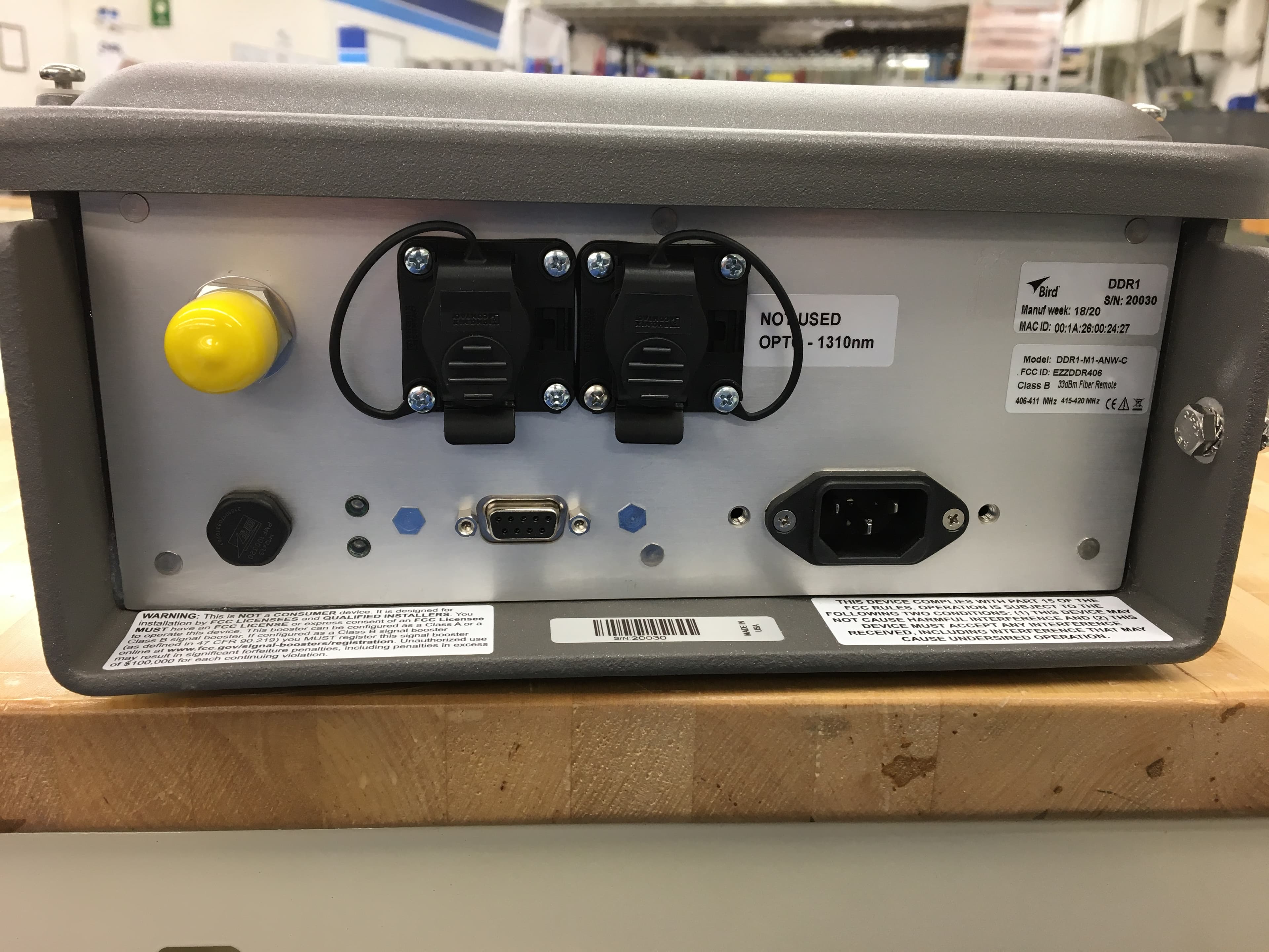
EZZDDR406
Jun 24, 2020DDR Low Band UHF Remote
Equipment Class
B9B - Part 90 Class B Industrial Booster (non-SMR)
EZZ61470
May 19, 2015UHF Digital Signal Booster
Equipment Class
B9A - Part 90 Class A Industrial Booster (non-SMR)
EZZ61470A
May 18, 2015UHF Digital Signal Booster
Equipment Class
B9A - Part 90 Class A Industrial Booster (non-SMR)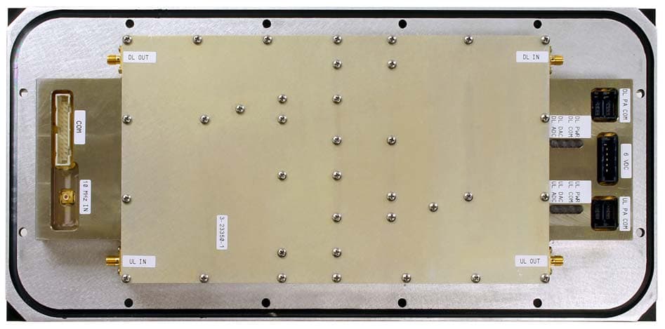
EZZ6138
Sep 21, 2011Channelized Signal Booster
Equipment Class
TNB - Licensed Non-Broadcast Station Transmitter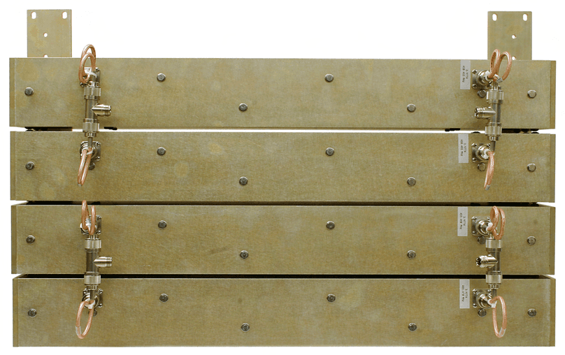
EZZ61170A
Mar 01, 2010Channelized Signal Booster
Equipment Class
TNB - Licensed Non-Broadcast Station Transmitter