EZZ61470UHF Digital Signal Booster
Bird Technologies Group
Click to zoom
Application Details
- Equipment Class
- B9A - Part 90 Class A Industrial Booster (non-SMR)
- Date of Grant
- May 19, 2015
- Application Purpose
- Original Equipment
- Date of Application
- Sep 29, 2014
- Equipment Note
- UHF Digital Signal Booster
- Frequency Range
- 455.00000000 - 470.00000000
- Company
- Bird Technologies Group
- Country
- United States
Documents & Files
Document Text
Text extracted from the exhibit documents filed with the FCC. Open a document above to read the original.
Users Manual
Bird Technologies Manual 7-9558-2.3 05/14/15 Page 1 8625 Industrial Parkway, Angola, NY 14006 Tel: 716-549-4700 Fax: 716-549-4772 [email protected] www.bird-technologies.com Installation and Operation Manual for the SBIII Digital Signal Booster Model 614 Manual Part Number 7-9558-2.3 DIGITAL TECHNOLOGY WARNING: This is NOT a consumer device. It is designed for installation by FCC Licensees and Qualified Installers. You must have an FCC license or express consent of an FCC Licensee to operate this device. This booster can be configured as either a Class A or Class B signal booster. If configured as a Class B signal booster (as defined in 47 CFR 90.219), you MUST register this signal booster online at www.fcc.gov/signal-booster/registration. Unau- thorized use may result in significant forfeiture penalties, including penalties in excess of $100,000 for each continuing violation. Bird Technologies Manual 7-9558-2.3 05/14/15 Page 2 Warranty This warranty applies for five years fr om shippi ng date TX RX Systems Inc. warrants its products to be free from defect in material and workmanship at the time of shipment. Our obligation under warranty is limited to replacement or repair, at our option, of any such products that shall have been defective at the time of manufacture. TX RX Systems Inc. reserves the right to replace with merchandise of equal performance although not identical in every way to that originally sold. TX RX Systems Inc. is not liable for dam- age caused by lightning or other natural disasters. No product will be accepted for repair or replacement without our prior written approval. The purchaser must prepay all shipping charges on returned products. TX RX Systems Inc. shall in no event be liable for consequential damages, installation costs or expense of any nature resulting from the purchase or use of products, whether or not they are used in accordance with instructions. This warranty is in lieu of all other warranties, either expressed or implied, including any implied warranty or merchantability of fitness. No repre- sentative is authorized to assume for TX RX Systems Inc. any other liability or warranty than set forth above in con- nection with our products or services. TERMS AND CONDITIONS OF SALE PRICES AND TERMS: Prices are FOB seller’s plant in Angola, NY domestic packaging only, and are subject to change without notice. Fed- eral, State and local sales or excise taxes are not included in prices. When Net 30 terms are applicable, payment is due within 30 days of invoice date. All orders are subject to a $100.00 net minimum. QUOTATIONS: Only written quotations are valid. ACCEPTANCE OF ORDERS: Acceptance of orders is valid only when so acknowledged in writing by the seller. SHIPPING: Unless otherwise agreed at the time the order is placed, seller reserves the right to make partial shipments for which payment shall be made in accordance with seller’s stated terms. Shipments are made with transportation charges col- lect unless otherwise specified by the buyer. Seller’s best judgement will be used in routing, except that buyer’s routing is used where practicable. The seller is not responsible for selection of most economical or timeliest routing. CLAIMS: All claims for damage or loss in transit must be made promptly by the buyer against the carrier. All claims for shortages must be made within 30 days after date of shipment of material from the seller’s plant. SPECIFICATION CHANGES OR MODIFICATIONS: All designs and specifications of seller’s products are subject to change without notice provided the changes or modifi- cations do not affect performance. RETURN MATERIAL: Product or material may be returned for credit only after written authorization from the seller, as to which seller shall have sole discretion. In the event of such authorization, credit given shall not exceed 80 percent of the original pur- chase. In no case will Seller authorize return of material more than 90 days after shipment from Seller’s plant. Credit for returned material is issued by the Seller only to the original purchaser. ORDER CANCELLATION OR ALTERATION: Cancellation or alteration of acknowledged orders by the buyer will be accepted only on terms that protect the seller against loss. NON WARRANTY REPAIRS AND RETURN WORK: Consult seller’s plant for pricing. Buyer must prepay all transportation charges to seller’s plant. Standard shipping pol- icy set forth above shall apply with respect to return shipment from TX RX Systems Inc. to buyer. DISCLAIMER Product part numbering in photographs and drawings is accurate at time of printing. Part number labels on TX RX products supersede part numbers given within this manual. Information is subject to change without notice. Bird Technologies Manual 7-9558-2.3 05/14/15 Page 3 Symbols Commonly Used NOTE VIDEO WARNING !!! CAUTION or ATTENTION Important Information Training Video Available Heavy Lifting High Voltage Hot Surface ESD Electrostatic Discharge Electrial Shock Hazard Safety Glasses Required Manual Part Number 7-9558 Copyright © 2015 Bird Technologies First Printing: June 2014 Version NumberVersion Date 106/16/14 1.107/14/14 1.209/23/14 1.311/13/14 2.002/23/15 2.104/07/15 2.204/29/15 2.305/14/15 Bird Technologies Manual 7-9558-2.3 05/14/15 Page 4 Table of Contents Overview ...............................................................................................................7 Down / Up Conversion .........................................................................................8 Unpacking ............................................................................................................9 Installation ............................................................................................................9 Location .............................................................................................................9 Mounting ...........................................................................................…
Text truncated - open the document above for the full version.
Cover Letter(s)
~rd Technologies® You're heard, loud and clear. June 19, 2014 Compliance Testing LLC 1724 S. Nevada Way Mesa, AZ 85204 RE: CONFIDENTIALITY REQUEST FOR: FCC ID: EZZ61470 Model: 614 (450-470MHz) SBIII UHF Digital Signal Booster To Whom It May Concern: This letter serves as an official request for confidentiality under sections 0.457 and 0.459 of CFR 47. We have requested that the following documents required to be submitted with this application be permanently withheld from public review. • Block Diagram • Schematics • Theory of Operation • Parts List/BOM These documents contain detailed system and equipment descriptions and related information about the product, which manufacturer/applicant considers being proprietary, confidential and a custom design and otherwise, would not release to the general public. Since this design is a basis from which future technological products will evolve, manufacturer/applicant feels that this information would be of benefit to its competitors, and that the disclosure of the information in these documents would give our competitors an unfair advantage in the market. Please contact me if there is any information you may need. Amy !J Sanvido On behalf of Bird Technologies 30303 Aurora Rd, Solon, OH 44139 I www.birdrf.com BIRD TECHNOLOGIES· r~o .... Aurar Rd. 01111 OH 4 ::j, oJ· • SA 6 . .bair! ( )n1 TX RX SYSTEMS· 86251ndu tri I P r f' AnlJ1 la, W I'JOO 716.549. 700· WW\ .birdrf.(orn X-COM SYSTEMS· 12345-8 Sunme V<llley Driv • R stun, VA 7(b 3901087· www.xcomsystems.«)m DElTANODE· H rnmaJb~ F brihvdg 1 6tl' E 1 030 )tvckholm, Sw ien· + f..708.7 1 11· dell nod.:.(O 11 ~rd Technologies® You're heard, loud and clear. e: [email protected] w : 440.519.2179 f: 440.248.9593 BIRD TECHNOLOGIES· 30303 AUlor Rd • ') Jlon. OH '1,'139·860.695.4569·' /" '.birdrf.com TX RX SYSTEMS· 8625 Industrial P rkway. AnCjold, NY 1·100'.!· I 16.54~1.4700· \'.'ww.birdrf.com X-COM SYSTEMS· 12345-B Slituisc VaH;:y Dtive· R!2 .. ton, VA . 70"'1.390.1087· w\I,,'w.xcom.,yst ... ms.(om DELTA NODE • H. mmarby F, briksvag 6 'I 6tr· Sf 12030 Sto(kholm, Sweden· +'16.708.781.511 • '. 'w\,.deltanod .(om
Cover Letter(s)
Dec. 18, 2014 Compliance Testing 1724 S. Nevada Way Mesa, AZ 85204 Attn: Greg Corbin EMC-RF Test Engineer Re: FCC PBA Response 9c for 614 series booster Our UHF 614 series booster utilizes two kinds of filtering. First, mechanical filters surround the RF chain to protect the inputs from overload and to reduce the harmonic emissions of the output. Secondly, programmable digital DSP filtering is employed within the RF chain to select only the desired channels which should be amplified. Input Mechanical Filtering The input mechanical filters select a section of the available downlink or uplink bands and provide rejection of the high level signals on the output of the booster. This is needed due to the interleaving of the downlink and uplink sections of the UHF Public safety band. It is not possible for the UHF booster to pass an entire downlink or uplink section because of the contiguous nature of the band-plan. Figure 1 shows an example system with 3 MHz input filtering. The mechanical filters are tunable in the factory only and are customized to the customers’ specific frequency range within the downlink and uplink bands and may have any pass-band width narrower than a downlink or uplink section. Output Mechanical Filtering The output mechanical filters were tested at the TCB and do not change. They are broadband and are used to reduce the harmonics that are produced by the power amplifier. Digital (DSP) Filtering The DSP filtering is located inside the channel module and is used to provide filtering for individual channels or groups of channels contained within the pass-band of the mechanical filtering. This filter passband can be programmed by the customer to be as narrow as 6.25kHz or as wide as 1.5MHz. Figure 2 depicts a typical arrangement of mechanical input filtering and narrow DSP filtering within the lower downlink/uplink section of the 450-470 MHz band. During the testing at the TCB, we set one of the DSP filters to the widest passband and moved the filter as needed. Two models are available that provide up to 14 filters or up to 30 filters. The difference between the models is the size of the DSP program image. The fit, form, and function is exactly the same. The filters are available for the customer to program different passbands. The need for the number of filters is based on how many channels the customer needs to isolate and whether some closely spaced channels may be grouped together. This allows our unit to be configurable in the field by the customer. The booster does not translate the channel to a different frequency, but passes it filtered and amplified to the output. Sincerely, Amy L Sanvido RF Design Engineer On behalf of Bird Technologies 30303 Aurora Rd, Solon, OH 44139 l www.birdrf.com e: [email protected] w: 440.519.2179 f: 440.248.9593
ID Label/Location Info
Channelized Signal Booster (Model 614) - Label Location Label Location on front panel of enclosure (450 - 470 MHz) Channelized Signal Booster (Model 614) - Label Location Label Location on front panel of enclosure (470 - 488 MHz) Channelized Signal Booster (Model 614) - Label Sample FCC and IC Label Sample (450 - 470 MHz) FCC and IC Label Sample (470 - 488 MHz)
Internal Photos
Channelized Signal Booster (Model 614) - Internal Photos Channel Module Board 3-23353-3 front view Channelized Signal Booster (Model 614) - Internal Photos Channel Module Board 3-23353-3 rear view Channelized Signal Booster (Model 614) - Internal Photos Downconverter Board 3-25111 front view Downconverter Board 3-25111 rear view Channelized Signal Booster (614) - Internal Photos Upconverter Board 3-25113-1 front view Upconverter Board 3-25113-1 rear view Channelized Signal Booster (614) - Internal Photos Upconverter Board 3-25113-2 front view Upconverter Board 3-25113-2 rear view Channelized Signal Booster (Model 614) - Internal Photos Upconverter Board 3-25113-3 front view Upconverter Board 3-25113-3 rear view Channelized Signal Booster (model 614) Internal Photos Upconverter Board 3-25113-4 front view Upconverter Board 3-25113-4 rear view Channelized Signal Booster (Model 614) - Internal Photos Upconverter Board 3-25113-5 front view Upconverter Board 3-25113-5 rear view Channelized Signal Booster (614) - Internal Photos Upconverter Board 3-25113-6 front view Upconverter Board 3-25113-6 rear view Channelized Signal Booster (Model 614) - Internal Photos Local Oscillator Board 3-25115 (1 through 4) front view Local Oscillator Board 3-25115 (1 through 4) rear view Channelized Signal Boosters (614) - Internal Photos Controller Board 3-23361-1 front view Controller Board 3-23361-1 rear view Channelized Signal Booster (Model 614) - Internal Photos Power Amplifier Board 3-25631 front view Power Amplifier Board 3-25631 rear view Channelized Signal Booster (Model 614) - Internal Photos Power Supply Mother Board 3-25358 front view Power Supply Mother Board 3-25358 rear view Channelized Signal Booster (Model 614) - Internal Photos Power Supply Daughter Board 3-25363 top front view Power Supply Daughter Board 3-25363 top back view Channelized Signal Booster (Model 614) - Internal Photos Power Supply Daughter Board 3-25363 bottom view Power Supply Daughter Board 3-25363 side view
Internal Photos
Channelized Signal Booster (Model 614) - External Photos Enclosure front view. Channelized Signal Booster (Model 614) - External Photos Enclosure top view. Channelized Signal Booster (Model 614) - External Photos Enclosure bottom view. Channelized Signal Booster (Model 614) - External Photos Enclosure close-up view. Channelized Signal Booster (Model 614) - External Photos Channel Module 3-25122 front view (cover plate removed) Channelized Signal Booster (Model 614) - External Photos Channel Module 3-25122 rear view (cover plate removed) Channelized Signal Booster (Model 614) - External Photos Channel Module 3-25123 front view (cover plate removed) Channelized Signal Booster (Model 614) - External Photos Channel Module 3-25123 rear view (cover plate removed) Channelized Signal Booster (Model 614) - External Photos Channel Module 3-25124 front view (cover plate removed) Channelized Signal Booster (Model 614) - External Photos Channel Module 3-25124 rear view (cover plate removed) Channelized Signal Booster (Model 614) - External Photos Channel Module 3-25125 front view (cover plate removed) Channelized Signal Booster (Model 614) - External Photos Channel Module 3-25125 rear view (cover plate removed) Channelized Signal Booster (Model 614) - External Photos Control Board 3-23360-1 front-right view. Control Board 3-23360-1 rear-right view. Channelized Signal Booster (Model 614) - External Photos Control Board 3-23360-1 top view. Control Board 3-23360-1 side view. Channelized Signal Booster (Model 614) - External Photos Power Amplifier 3-25406 top view Power Amplifier 3-25406 right side view Power Amplifier 3-25406 left side view Channelized Signal Booster (Model 614) - External Photos Power Supply Assembly front view (part # 3-25381). Power Supply Assembly rear view (part # 3-25381). Channelized Signal Booster (Model 614) - External Photos Power Supply front-side view (part # 3-25381). Power Supply edge view (part # 3-25381). Channelized Signal Booster (Model 614) - External Photos Circulator 8-8192P top view Circulator 8-8192P front side view Circulator 8-8192P rear side view Channelized Signal Booster (Model 614) - External Photos Line Filter top view. (part # 8-23887) Line Filter left view. (part # 8-23887) Line Filter right view. (part # 8-23887) Channelized Signal Booster (Model 614) - External Photos DC Line Filter top view (part # 8-25384) Channelized Signal Booster (Model 614) - External Photos Filter Assembly top view. (part # 8-25293) Filter Assembly side view. (part # 8-25293) Channelized Signal Booster (Model 614) - External Photos Filter Assembly top view (part # 8-25294) Filter Assembly side view (part # 8-25294) Channelized Signal Booster (Model 614) - External Photos Filter Assembly top view (part # 8-25295) Filter Assembly side view (part # 8-25295) Channelized Signal Booster (Model 614) - External Photos Filter Assembly top view (part # 8-25296) Filter Assembly side view (part # 8-25296)
RF Exposure Info
p1460007_FCC_Part 1.1310_Rev 5.0 Page 1 of 8 Test Report Prepared for: Bird Technologies Group Model: 614 Series/450-470MHz Description: UHF Digital Signal Booster FCC ID: EZZ61470 To FCC Part 1.1310 Date of Issue: May 14, 2015 On the behalf of the applicant: Bird Technologies Group 30303 Aurora Road Solon, OH 44139 Attention of: Amy Sanvido, RF Engineer Ph: (440) 519-2179 E-Mail: [email protected] Prepared By Compliance Testing, LLC 1724 S. Nevada Way Mesa, AZ 85204 (480) 926-3100 phone / (480) 926-3598 fax www.compliancetesting.com Project No: p1460007 Greg Corbin Project Test Engineer This report may not be reproduced, except in full, without written permission from Compliance Testing All results contained herein relate only to the sample tested p1460007_FCC_Part 1.1310_Rev 5.0 Page 2 of 8 Test Report Revision History Revision Date Revised By Reason for Revision 1.0 August 11, 2014 Greg Corbin Original Document 2.0 September 18, 2014 Mike Graffeo Corrected antenna gain/loss to -4dBi 3.0 October 29, 2014 Greg Corbin Corrected report to show power spectral density calculations in place of minimum safe distance 4.0 April 27, 2015 Greg Corbin Changed exposure environment from Controlled to Uncontrolled and calculated new limits. 5.0 May 12, 2015 Greg Corbin Added MPE calculations for all modes of operation, including mfr rated power + 20% p1460007_FCC_Part 1.1310_Rev 5.0 Page 3 of 8 ILAC / A2LA Compliance Testing, LLC, has been accredited in accordance with the recognized International Standard ISO/IEC 17025:2005. This accreditation demonstrates technical competence for a defined scope and the operation of a laboratory quality management system (refer joint ISO-ILAC-IAF Communiqué dated January 2009) The tests results contained within this test report all fall within our scope of accreditation, unless below Please refer to http://www.compliancetesting.com/labscope.html for current scope of accreditation. Testing Certificate Number: 2152.01 FCC Site Reg. #349717 IC Site Reg. #2044A-2 Non-accredited tests contained in this report: N/A EUT Description Model: 614 Series/450-470MHz Description: UHF Digital Signal Booster Firmware: R21.D6 Software: N/A Additional Information: The EUT is a Class B industrial UHF digital signal booster operating from 450 – 470 MHz. The downlink operates from 450 – 465 MHz and the uplink operates from 455 – 470 MHz. Each band has a low power and high power output, configurable in software but not available to the end user, the selection of either low or high power is a factory setting only. MPE calculations were performed for the downlink at low and high power using an antenna with – 4 dBi gain. MPE calculations were performed on the uplink at low and high power using an antenna with – 1.28 dBi gain. . MPE calculations were performed at the manufacturer’s rated output of +37 dBm +20 % using an antenna with 0 dBi gain. p1460007_FCC_Part 1.1310_Rev 5.0 Page 4 of 8 MPE Evaluation This is a Fixed device used in an Uncontrolled Exposure environment. Limits Uncontrolled Exposure 47 CFR 1.1310 Table 1, (B) 0.3-1.234 MHz: Limit [mW/cm²] = 100 1.34-30 MHz: Limit [mW/cm²] = (180/f²) 30-300 MHz: Limit [mW/cm²] = 0.2 300-1500 MHz: Limit [mW/cm²] = f/1500 1500-100,000 MHz Limit [mW/cm²] = 1.0 Test Data Uplink Output Power set to manufacturer’s (Mfr) rated output power (+37 dBm) + 20 % using an antenna with 0 dBi gain Test Frequency, MHz 455 Power, Mfr rated, mW (P) 5012 Power, Mfr rated + 20%, mW (P) 6014.4 mw (37.79 dBm) Antenna Gain Isotropic 0 dBi Antenna Gain Numeric (G) 1 Distance (R) 20 cm ൌܵ ܩ∗ܲ ݎߨ4 ଶ Power Density (S) mw/cm 2 Power mW (P) Numeric Gain (G) Distance (r 2 ) cm 1.197 6014.4 1 20 Power Density (S) = 1.197 mw/cm 2 Limit =(from above table) = 0.303mw/cm 2 With the Uplink output power set to (Mfr) rated output power (+37 dBm) + 20 % using a 0 dBi antenna, the EUT does not meet the power density requirements at 20 cm, so the minimum safe distance was calculated below. Minimum Safe Distance Evaluation Test Data Uplink Output Power set to manufacturer’s (Mfr) rated output power (+37 dBm) + 20 % using an antenna with 0 dBi gain Test Frequency, MHz 455 Power, Mfr rated, mW (P) 5012 Power, Mfr rated + 20%, mW (P) 6014.4 mw (37.79 dBm) Antenna Gain Isotropic 0 dBi Antenna Gain Numeric (G) 1 Limit (L) 0.303 R=√(PG/4πL) Distance (R) cm Power mW (P) Numeric Gain (G) Limit (L) 39.8 6014.4 0 0.303 With the Uplink Output Power set to the manufacturer’s (Mfr) rated output power (+37 dBm) + 20 % using an antenna with 0 dBi gain , the minimum safe distance is 39.8 cm. p1460007_FCC_Part 1.1310_Rev 5.0 Page 5 of 8 MPE Evaluation This is a Fixed device used in an Uncontrolled Exposure environment. Limits Uncontrolled Exposure 47 CFR 1.1310 Table 1, (B) 0.3-1.234 MHz: Limit [mW/cm²] = 100 1.34-30 MHz: Limit [mW/cm²] = (180/f²) 30-300 MHz: Limit [mW/cm²] = 0.2 300-1500 MHz: Limit [mW/cm²] = f/1500 1500-100,000 MHz Limit [mW/cm²] = 1.0 Test Data Downlink high power mode using a - 4.0 dBi antenna Test Frequency, MHz 450.5 Power, Conducted, mW (P) 4266 Antenna Gain Isotropic - 4.0 dBi Antenna Gain Numeric (G) 0.4 Distance (R) 20 cm ൌܵ ܩ∗ܲ ݎߨ4 ଶ Power Density (S) mw/cm 2 Power mW (P) Numeric Gain (G) Distance (r 2 ) cm 0.339 4266 0.4 20 Power Density (S) =0.339 mw/cm 2 Limit =(from above table) = 0.300 mw/cm 2 In the Downlink high power operating mode, the EUT does not meet the power density requirements at 20 cm, so the minimum safe distance was calculated below. Minimum Safe Distance Evaluation Test Data Downlink high power operating mode using a - 4.0 dBi antenna Test Frequency, MHz 450.5 Power, Conducted, mW (P) 4266 Antenna Gain Isotropic - 4.0 dBi Antenna Gain Numeric (G) 0.4 Limit (L) 0.300 R=√(PG/4πL) Distance (R) cm Power mW (P) Numeric Gain (G) Limit (L) 21.28 4266 0.4 0.300 The minimum safe distance with a – 4.0 dBi antenna is 21.3 cm In the Downlink high power operating mode. p1460007_FCC_Part 1.1310_Rev 5.0 Page 6 of 8 MPE Evaluation This is a Fixed device us…
Text truncated - open the document above for the full version.
Test Report
p1460007_FCC_Part 90_Rev 6.0 Page 1 of 42 Test Report Prepared for: Bird Technologies Group Model: 614 450-470MHz Description: SBIII UHF Digital Signal Booster FCC ID: EZZ61470 To FCC Part 90 Date of Issue: May 14, 2015 On the behalf of the applicant: Bird Technologies Group 30303 Aurora Road Solon, OH 4413 Attention of: Amy Sanvido, RF Engineer Ph: (440) 519-2179 E-Mail: [email protected] Prepared By Compliance Testing, LLC 1724 S. Nevada Way Mesa, AZ 85204 (480) 926-3100 phone / (480) 926-3598 fax www.compliancetesting.com Project No: p1460007 Greg Corbin Project Test Engineer This report may not be reproduced, except in full, without written permission from Compliance Testing All results contained herein relate only to the sample tested p1460007_FCC_Part 90_Rev 6.0 Page 2 of 42 Test Report Revision History Revision Date Revised By Reason for Revision 1.0 June 26, 2014 Greg Corbin Original Document 2.0 October 31, 2014 Greg Corbin Updated references on the Test Summary Table, Added Input plots for Occupied Bandwidth, Added section for Radiated Output Power 3.0 December 17, 2014 Greg Corbin Added block diagram and model number of unit as tested to page 6. Added F1W emission designator to the table on page 7. 4.0 January 5, 2014 Greg Corbin Removed emission designator F1W from the table on page 7 5.0 April 27, 2015 Greg Corbin Added clarification to the narrowband filter description on page 6 6.0 May 12.2015 Greg Corbin Revised ERP statement at bottom of page 13 p1460007_FCC_Part 90_Rev 6.0 Page 3 of 42 Table of Contents Description Page Standard Test Conditions and Engineering Practices 5 Test Result Summary 9 Out of Band Rejection 10 Conducted Output Power and Amplifier Gain 13 Radiated Output Power 13 Conducted Spurious Emissions 14 Radiated Spurious Emissions 19 Emission Masks (Occupied Bandwidth) 20 Intermodulation 37 Noise Figure Test 41 Test Equipment Utilized 42 p1460007_FCC_Part 90_Rev 6.0 Page 4 of 42 ILAC / A2LA Compliance Testing, LLC, has been accredited in accordance with the recognized International Standard ISO/IEC 17025:2005. This accreditation demonstrates technical competence for a defined scope and the operation of a laboratory quality management system (refer joint ISO-ILAC-IAF Communiqué dated January 2009) The tests results contained within this test report all fall within our scope of accreditation, unless noted below. Please refer to http://www.compliancetesting.com/labscope.html for current scope of accreditation. Testing Certificate Number: 2152.01 FCC Site Reg. #349717 IC Site Reg. #2044A-2 Non-accredited tests contained in this report: N/A p1460007_FCC_Part 90_Rev 6.0 Page 5 of 42 The Applicant has been cautioned as to the following: 15.21: Information to the User The user’s manual or instruction manual for an intentional radiator shall caution the user that changes or modifications not expressly approved by the party responsible for compliance could void the user’s authority to operate the equipment. 15.27(a): Special Accessories Equipment marketed to a consumer must be capable of complying with the necessary regulations in the configuration in which the equipment is marketed. Where special accessories, such as shielded cables and/or special connectors are required to enable an unintentional or intentional radiator to comply with the emission limits in this part, the equipment must be marketed with, i.e. shipped and sold with, those special accessories. However, in lieu of shipping or packaging the special accessories with the unintentional or intentional radiator, the responsible party may employ other methods of ensuring that the special accessories are provided to the consumer, without an additional charge. Information detailing any alternative method used to supply the special accessories for a grant of equipment authorization or retained in the verification records, as appropriate. The party responsible for the equipment, as detailed in § 2.909 of this chapter, shall ensure that these special accessories are provided with the equipment. The instruction manual for such devices shall include appropriate instructions on the first page of text concerned with the installation of the device that these special accessories must be used with the device. It is the responsibility of the user to use the needed special accessories supplied with the equipment. Test and Measurement Data All tests and measurement data shown were performed in accordance with FCC Rules and Regulations Part 90.219, KDB 935210 D03 Booster, and FCC Part 2, where appropriate. Standard Test Conditions and Engineering Practices Except as noted herein, the following conditions and procedures were observed during the testing. In accordance with ANSI/TIA 603C, and unless otherwise indicated in the specific measurement results, the ambient temperature of the actual EUT was maintained within the range of 10° to 40°C (50° to 104°F) unless the particular equipment requirements specify testing over a different temperature range. Also, unless otherwise indicated, the humidity levels were in the range of 10% to 90% relative humidity. Environmental Conditions Temp (ºC) Humidity (%) Pressure (mbar) 23.0 – 29.4 23.3 – 38.1 960.8 – 968.5 Measurement results, unless otherwise noted, are worst-case measurements. p1460007_FCC_Part 90_Rev 6.0 Page 6 of 42 EUT Description ModelTested: 614‐70‐A‐HH‐G1‐B (High Power) and 614‐70‐A‐LL‐G1‐B (Low Power) Description: Class B UHF Digital Signal Booster Firmware: R21.D6 Software: N/A Additional Information: The EUT is a Class B industrial UHF digital signal booster operating from 450 – 470 MHz. The downlink operates from 450 – 465 MHz and the uplink operates from 455 – 470 MHz. Each band has a low power and high power output, configurable in software but not available to the end user, the selection of either low or high power is a factory setting only. All the test data was recorded in both the low power and high power modes of operation. The downlink and upl…
Text truncated - open the document above for the full version.
Test Setup Photos
Test Setup Photos FCC ID: EZZ61470 RF Conducted #1 RF Conducted #2 RF Radiated #1 RF Radiated #2
Contact Information
Applicant
Amy Sanvido(RF Engineer)
Test Firm
Compliance Testing, LLCMichael Schafer
Technical Specifications
| # | Rule Parts | Frequency Range | Power Output | Emission |
|---|---|---|---|---|
| 6 | 9 | 455 MHz - 470 MHz | 4.68 W | F1D |
Other Applications from Bird Technologies Group
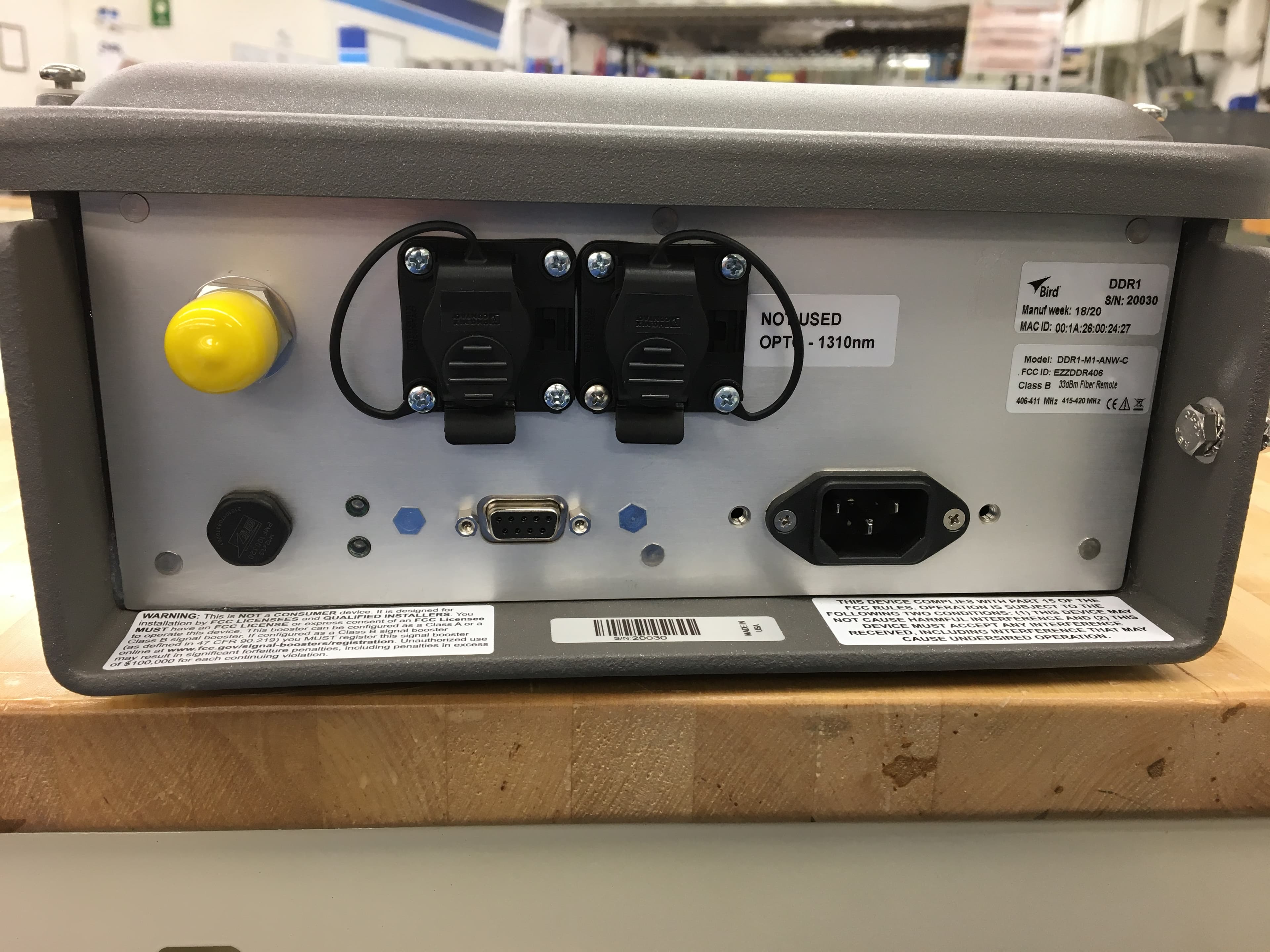
EZZDDR406
Jun 24, 2020DDR Low Band UHF Remote
Equipment Class
B9B - Part 90 Class B Industrial Booster (non-SMR)
EZZ61470A
May 18, 2015UHF Digital Signal Booster
Equipment Class
B9A - Part 90 Class A Industrial Booster (non-SMR)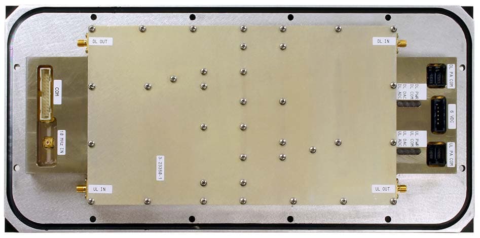
EZZ6138
Sep 21, 2011Channelized Signal Booster
Equipment Class
TNB - Licensed Non-Broadcast Station Transmitter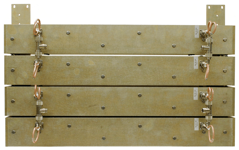
EZZ61170A
Mar 01, 2010Channelized Signal Booster
Equipment Class
TNB - Licensed Non-Broadcast Station Transmitter
EZZ5PI616550
Sep 21, 2006SIGNAL BOOSTER II (SB II)
Equipment Class
TNB - Licensed Non-Broadcast Station Transmitter