EZZDDR406DDR Low Band UHF Remote
Bird Technologies Group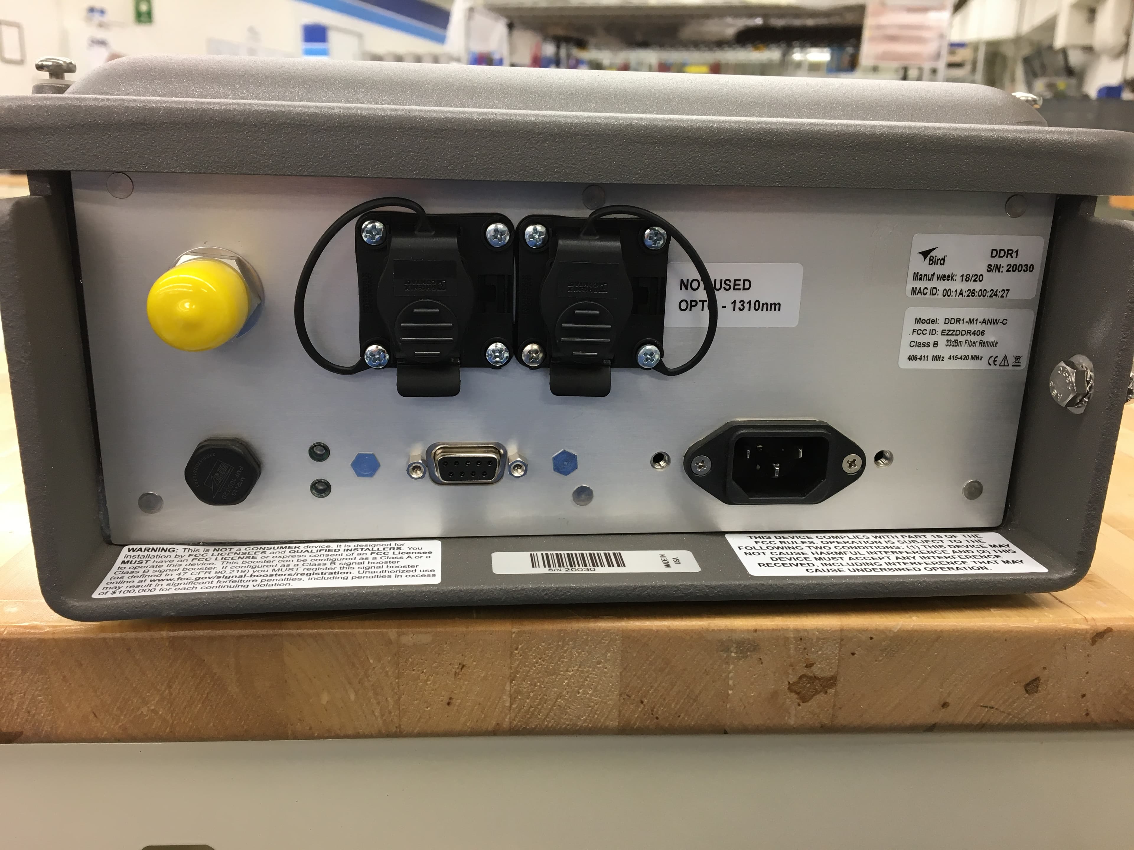
Click to zoom
Application Details
- Equipment Class
- B9B - Part 90 Class B Industrial Booster (non-SMR)
- Date of Grant
- Jun 24, 2020
- Application Purpose
- Original Equipment
- Date of Application
- Jun 24, 2020
- Equipment Note
- DDR Low Band UHF Remote
- Frequency Range
- 406.10000000 - 411.00000000
- Company
- Bird Technologies Group
- Country
- United States
Documents & Files
Document Text
Text extracted from the exhibit documents filed with the FCC. Open a document above to read the original.
Users Manual
Fiber Distributed Antenna System (Fiber DAS) Operation Manual ©Copyright 2019 by Bird Technologies, Inc. Instruction Book Part Number 920-Fiber-DAS Rev. P5 Delta Node® is a registered trademark of Delta Node Solutions Ltd. and Bird Technologies, Inc. i Safety Precautions The following are general safety precautions that are not necessarily related to any specific part or procedure, and do not necessarily appear elsewhere in this publication. These precautions must be thoroughly understood and apply to all phases of operation and maintenance. WARNING Keep Away From Live Circuits Operating Personnel must at all times observe general safety precautions. Do not replace components or make adjustments to the inside of the test equipment with the high voltage supply turned on. To avoid casualties, always remove power. WARNING Shock Hazar d Do not attempt to remove the RF transmission line while RF power is present. WARNING Do Not Service Or Adjus t Alone Under no circumstances should any person reach into an enclosure for the purpose of service or adjustment of equipment except in the presence of someone who is capable of rendering aid. WARNING Safety Earth Ground An uninterruptible earth safety ground must be supplied from the main power source to test instruments. Grounding one conductor of a two conductor power cable is not sufficient protection. Serious injury or death can occur if this grounding is not properly supplied. WARNING Resuscitation Personnel working with or near high voltages should be familiar with modern methods of resuscitation. WARNING Remove Power Observe general safety precautions. Do not open the instrument with the power applied. Safety Precautions ii Safety Symbols WARNING Warning notes call attention to a procedure, which if not correctly performed, could result in personal injury. CAUTION Caution notes call attention to a procedure, which if not correctly performed, c ould result in damage to the instrument. Note: Calls attention to supplemental information. The laser used in this system is a Class 3b laser that produces invisible infra-red coherent light. Avoid looking into connected fibers and receptacles. Not safe to view with optical instruments. Always put the protection caps on unused fibers and receptacles. Fiber Distributed Antenna System (Fiber DAS) iii Warning Statements The following safety warnings appear in the text where there is danger to operating and maintenance personnel and are repeated here for emphasis. WARNING This is NOT a consumer device. It is design for installation by FCC LICENSEES and QUALIFIED INSTALLERS. You MUST have an FCC LICENSE or express consent of an FCC licensee to operate this device. You MUST register Class B signal boosters (as defined in 47 CFR 90.219) online at www.fcc.gov/signal-boosters/registration. Unauthorized use may result in significant forfeiture penalties, including penalties in excess of $100,000 for each c ontinuing violation. See page 43 For CMRS 817-824MHz Applications and American Cellular Applications: WARNING This is NOT a consumer device. It is design for installation by FCC LICENSEES and QUALIFIED INSTALLERS. You MUST have an FCC LICENSE or express consent of an FCC licensee to operate this device. Unauthorized use may result in significant forfeiture penalties, including penalties in excess of $100,000 for each continuing violation. See page 43 WARNING This is NOT a consumer device. It is designed for installation by an installer approved by an ISED licensee. You MUST have an ISED LICENCE or the express consent of an ISED licensee to operate this device. WARNING Avoid looking into connected fibers and receptacles. The laser used in this system is a Class 3b laser that produces invisible infra-red coherent light. Not safe to view with optical instruments. Always put the protection caps on unused fibers and receptacles. See page 43 See page 15 Safety Precautions iv Caution Statements The following equipment cautions appear in the text and are repeated here for emphasis. CAUTION Turn Off Test Tone Do not forget to turn off the test tone when you are done with your uplink. Better check one extra time. They will otherwise interfere with the normal operation of the system by causing noise to the base station. See page 118 CAUTION Unauthorized antennas, cables, and/or coupling devices may cause non-conformity with national or international regulations, could cause damage, or non-conforming ERP/EIRP. See page 44. CAUTION When mating RF connectors, ensure that they are properly aligned and not cross threaded. Tighten SMA connectors to 8 in.-lbs. Do over torque RF connectors, this could result in damage to the Unit. Do not under torque RF connectors, this could result in poor signal transmission. See page 50 Fiber Distributed Antenna System (Fiber DAS) v Safety Statements USAGE ANY USE OF THIS INSTRUMENT IN A MANNER NOT SPECIFIED BY THE MANUFACTURER MAY IMPAIR THE INSTRUMENT’S SAFETY PROTECTION. USO EL USO DE ESTE INSTRUMENTO DE MANERA NO ESPECIFICADA POR EL FABRICANTE, PUEDE ANULAR LA PROTECCIÓN DE SEGURIDAD DEL INSTRUMENTO. BENUTZUNG WIRD DAS GERÄT AUF ANDERE WEISE VERWENDET ALS VOM HERSTELLER BESCHRIEBEN, KANN DIE GERÄTESICHERHEIT BEEINTRÄCHTIGT WERDEN. UTILISATION TOUTE UTILISATION DE CET INSTRUMENT QUI N’EST PAS EXPLICITEMENT PRÉVUE P AR LE FABRICANT PEUT ENDOMMAGER LE DISPOSITIF DE PROTECTION DE L’INSTRUMENT. IMPIEGO QUALORA QUESTO STRUMENTO VENISSE UTILIZZATO IN MODO DIVERSO DA COME SPECIFICATO DAL PRODUTTORE LA PROZIONE DI SICUREZZA POTREBBE VENIRNE COMPROMESSA. Safety Precautions vi SERVICE SERVICING INSTRUCTIONS ARE FOR USE BY SERVICE - TRAINED PERSONNEL ONLY. TO AVOID DANGEROUS ELECTRIC SHOCK, DO NOT PERFORM ANY SERVICING UNLESS QUALIFIED TO DO SO. SERVICIO LAS INSTRUCCIONES DE SERVICIO SON PARA USO EXCLUSIVO DEL PERSONAL DE SERVICIO CAPACITADO. PARA EVITAR EL PELIGRO DE DESCARGAS ELÉCTRICAS, NO REALICE NINGÚN SERVICIO A MENOS QUE ESTÉ CAPACITADO PARA HACERIO. WARTUNG ANWEISUNGEN FÜR DIE WARTUNG DES GERÄT…
Text truncated - open the document above for the full version.
Users Manual
Fiber Distributed Antenna System (Fiber DAS) Operation Manual ©Copyright 2019 by Bird Technologies, Inc. Instruction Book Part Number 920-Fiber-DAS Rev. P5 Delta Node® is a registered trademark of Delta Node Solutions Ltd. and Bird Technologies, Inc. i Safety Precautions The following are general safety precautions that are not necessarily related to any specific part or procedure, and do not necessarily appear elsewhere in this publication. These precautions must be thoroughly understood and apply to all phases of operation and maintenance. WARNING Keep Away From Live Circuits Operating Personnel must at all times observe general safety precautions. Do not replace components or make adjustments to the inside of the test equipment with the high voltage supply turned on. To avoid casualties, always remove power. WARNING Shock Hazar d Do not attempt to remove the RF transmission line while RF power is present. WARNING Do Not Service Or Adjus t Alone Under no circumstances should any person reach into an enclosure for the purpose of service or adjustment of equipment except in the presence of someone who is capable of rendering aid. WARNING Safety Earth Ground An uninterruptible earth safety ground must be supplied from the main power source to test instruments. Grounding one conductor of a two conductor power cable is not sufficient protection. Serious injury or death can occur if this grounding is not properly supplied. WARNING Resuscitation Personnel working with or near high voltages should be familiar with modern methods of resuscitation. WARNING Remove Power Observe general safety precautions. Do not open the instrument with the power applied. Safety Precautions ii Safety Symbols WARNING Warning notes call attention to a procedure, which if not correctly performed, could result in personal injury. CAUTION Caution notes call attention to a procedure, which if not correctly performed, c ould result in damage to the instrument. Note: Calls attention to supplemental information. The laser used in this system is a Class 3b laser that produces invisible infra-red coherent light. Avoid looking into connected fibers and receptacles. Not safe to view with optical instruments. Always put the protection caps on unused fibers and receptacles. Fiber Distributed Antenna System (Fiber DAS) iii Warning Statements The following safety warnings appear in the text where there is danger to operating and maintenance personnel and are repeated here for emphasis. WARNING This is NOT a consumer device. It is design for installation by FCC LICENSEES and QUALIFIED INSTALLERS. You MUST have an FCC LICENSE or express consent of an FCC licensee to operate this device. You MUST register Class B signal boosters (as defined in 47 CFR 90.219) online at www.fcc.gov/signal-boosters/registration. Unauthorized use may result in significant forfeiture penalties, including penalties in excess of $100,000 for each c ontinuing violation. See page 43 For CMRS 817-824MHz Applications and American Cellular Applications: WARNING This is NOT a consumer device. It is design for installation by FCC LICENSEES and QUALIFIED INSTALLERS. You MUST have an FCC LICENSE or express consent of an FCC licensee to operate this device. Unauthorized use may result in significant forfeiture penalties, including penalties in excess of $100,000 for each continuing violation. See page 43 WARNING This is NOT a consumer device. It is designed for installation by an installer approved by an ISED licensee. You MUST have an ISED LICENCE or the express consent of an ISED licensee to operate this device. WARNING Avoid looking into connected fibers and receptacles. The laser used in this system is a Class 3b laser that produces invisible infra-red coherent light. Not safe to view with optical instruments. Always put the protection caps on unused fibers and receptacles. See page 43 See page 15 Safety Precautions iv Caution Statements The following equipment cautions appear in the text and are repeated here for emphasis. CAUTION Turn Off Test Tone Do not forget to turn off the test tone when you are done with your uplink. Better check one extra time. They will otherwise interfere with the normal operation of the system by causing noise to the base station. See page 118 CAUTION Unauthorized antennas, cables, and/or coupling devices may cause non-conformity with national or international regulations, could cause damage, or non-conforming ERP/EIRP. See page 44. CAUTION When mating RF connectors, ensure that they are properly aligned and not cross threaded. Tighten SMA connectors to 8 in.-lbs. Do over torque RF connectors, this could result in damage to the Unit. Do not under torque RF connectors, this could result in poor signal transmission. See page 50 Fiber Distributed Antenna System (Fiber DAS) v Safety Statements USAGE ANY USE OF THIS INSTRUMENT IN A MANNER NOT SPECIFIED BY THE MANUFACTURER MAY IMPAIR THE INSTRUMENT’S SAFETY PROTECTION. USO EL USO DE ESTE INSTRUMENTO DE MANERA NO ESPECIFICADA POR EL FABRICANTE, PUEDE ANULAR LA PROTECCIÓN DE SEGURIDAD DEL INSTRUMENTO. BENUTZUNG WIRD DAS GERÄT AUF ANDERE WEISE VERWENDET ALS VOM HERSTELLER BESCHRIEBEN, KANN DIE GERÄTESICHERHEIT BEEINTRÄCHTIGT WERDEN. UTILISATION TOUTE UTILISATION DE CET INSTRUMENT QUI N’EST PAS EXPLICITEMENT PRÉVUE P AR LE FABRICANT PEUT ENDOMMAGER LE DISPOSITIF DE PROTECTION DE L’INSTRUMENT. IMPIEGO QUALORA QUESTO STRUMENTO VENISSE UTILIZZATO IN MODO DIVERSO DA COME SPECIFICATO DAL PRODUTTORE LA PROZIONE DI SICUREZZA POTREBBE VENIRNE COMPROMESSA. Safety Precautions vi SERVICE SERVICING INSTRUCTIONS ARE FOR USE BY SERVICE - TRAINED PERSONNEL ONLY. TO AVOID DANGEROUS ELECTRIC SHOCK, DO NOT PERFORM ANY SERVICING UNLESS QUALIFIED TO DO SO. SERVICIO LAS INSTRUCCIONES DE SERVICIO SON PARA USO EXCLUSIVO DEL PERSONAL DE SERVICIO CAPACITADO. PARA EVITAR EL PELIGRO DE DESCARGAS ELÉCTRICAS, NO REALICE NINGÚN SERVICIO A MENOS QUE ESTÉ CAPACITADO PARA HACERIO. WARTUNG ANWEISUNGEN FÜR DIE WARTUNG DES GERÄT…
Text truncated - open the document above for the full version.
Cover Letter(s)
30303 AURORA RD, SOLON, OH 44139 1875 CAMPUS COMMONS DR, STE. 101 RESTON, VA 20191 T: 440.248.1200 / 866.695.4569 F: 440.248.5426 / 866.546.4306 WWW.BIRDRF.COM May 26, 2020 Federal Communications Commission Authorization & Evaluation Division 7345 Oakland Mills Road Columbia, Maryland 21046 RE: LETTER OF AGENT AUTHORIZATION To Whom It May Concern: We, the undersigned, hereby authorize Compliance Testing, LLC to act on our behalf in all matters relating to application for equipment authorization, including the signing of all documents relating to these matters. We also hereby certify that no party to the application authorized hereunder is subject to the denial of benefits, including FCC benefits, pursuant to Section 5301 of the Anti-Drug Abuse Act of 1988, 21 U.S.C.853(a). Sincerely, Amy Sanvido On behalf of Bird Technologies l www.birdrf.com Agile Engineering Manager – Public Safety w: 440.519.2179 e: [email protected]
Cover Letter(s)
30 303 AURORA RD, SOLON, OH 44139 1875 CAMPUS COMMONS DR, STE. 101 RESTON, VA 20191 T: 440.248.1200 / 866.695.4569 F: 440.248.5426 / 866.546.4306 WWW.BIRDRF.COM May 26, 2020 Feder al Communications Commission Authorization & Evaluation Division 7345 Oakland Mills Road Columbia, Maryland 21046 R E: Long-Term Confidentiality Request for: Product #: DDR1-M FCC ID: V5FDDR406 To W hom It May Concern: Thi s letter serves as an official request for confidentiality under § 0.457(d) and § 0.459 of CFR 47. We have requested that the following documents required to be submitted with this application be permanently withheld from public review. •Block Diagram •Schematics •Theory of Operation •Parts List/BOM Thes e documents contain detailed system and equipment descriptions and related information about the product, which manufacturer/applicant considers to be proprietary, confidential, and a custom design and otherwise, would not release to the general public. Since this design is a basis from which future technological products will evolve, manufacturer/applicant feels that this information would be of benefit to its competitors, and that the disclosure of the information in these documents would give our competitors an unfair advantage in the market. P lease contact me if there is any information you may need. S incerely, A my Sanvido On behalf of Bird Technologies l www.birdrf.com Agile Engineering Manager – Public Safety w: 440.519.2179 e: [email protected]
Cover Letter(s)
30303 AURORA RD, SOLON, OH 44139 1875 CAMPUS COMMONS DR, STE. 101 RESTON, VA 20191 T: 440.248.1200 / 866.695.4569 F: 440.248.5426 / 866.546.4306 WWW.BIRDRF.COM May 26, 2020 Federal Communications Commission Authorization & Evaluation Division 7345 Oakland Mills Road Columbia, Maryland 21046 RE: LETTER OF AGENT AUTHORIZATION To Whom It May Concern: We, the undersigned, hereby authorize Compliance Testing, LLC to act on our behalf in all matters relating to application for equipment authorization, including the signing of all documents relating to these matters. We also hereby certify that no party to the application authorized hereunder is subject to the denial of benefits, including FCC benefits, pursuant to Section 5301 of the Anti-Drug Abuse Act of 1988, 21 U.S.C.853(a). Sincerely, Amy Sanvido On behalf of Bird Technologies l www.birdrf.com Agile Engineering Manager – Public Safety w: 440.519.2179 e: [email protected]
Cover Letter(s)
30 303 AURORA RD, SOLON, OH 44139 1875 CAMPUS COMMONS DR, STE. 101 RESTON, VA 20191 T: 440.248.1200 / 866.695.4569 F: 440.248.5426 / 866.546.4306 WWW.BIRDRF.COM May 26, 2020 Feder al Communications Commission Authorization & Evaluation Division 7345 Oakland Mills Road Columbia, Maryland 21046 R E: Long-Term Confidentiality Request for: Product #: DDR1-M FCC ID: V5FDDR406 To W hom It May Concern: Thi s letter serves as an official request for confidentiality under § 0.457(d) and § 0.459 of CFR 47. We have requested that the following documents required to be submitted with this application be permanently withheld from public review. •Block Diagram •Schematics •Theory of Operation •Parts List/BOM Thes e documents contain detailed system and equipment descriptions and related information about the product, which manufacturer/applicant considers to be proprietary, confidential, and a custom design and otherwise, would not release to the general public. Since this design is a basis from which future technological products will evolve, manufacturer/applicant feels that this information would be of benefit to its competitors, and that the disclosure of the information in these documents would give our competitors an unfair advantage in the market. P lease contact me if there is any information you may need. S incerely, A my Sanvido On behalf of Bird Technologies l www.birdrf.com Agile Engineering Manager – Public Safety w: 440.519.2179 e: [email protected]
ID Label/Location Info
Example For Label Placement Only Part 90 Signal Boosters THIS IS A 90.219 CLASS B DEVICE WARNING. This is NOT a CONSUMER device. It is designed for installation by FCC LICENSEES and QUALIFIED INSTALLERS. You MUST have an FCC LICENSE or express consent of an FCC licensee to operate this device. You MUST register Class B signal boosters (as defined in 47 CFR 90.219) online at www.fcc. g ov/si g nal-boosters/re g istration. Unauthorized use may result in significant forfeiture penalties, including penalties in excess of $100,000 for each continuing violation. �rd" DDR1 S/N: 99991 Manuf week: 18/20 MAC ID: 00:1A:26:00:4B:18 Model: DDR1-M1-ANW-C FCC ID: EZZDDR406 Class B 33dBm Fiber Remote 406-411 MHZ 415-420 MHz CE.&x!
ID Label/Location Info
Example For Label Placement Only Part 90 Signal Boosters THIS IS A 90.219 CLASS B DEVICE WARNING. This is NOT a CONSUMER device. It is designed for installation by FCC LICENSEES and QUALIFIED INSTALLERS. You MUST have an FCC LICENSE or express consent of an FCC licensee to operate this device. You MUST register Class B signal boosters (as defined in 47 CFR 90.219) online at www.fcc. g ov/si g nal-boosters/re g istration. Unauthorized use may result in significant forfeiture penalties, including penalties in excess of $100,000 for each continuing violation. �rd" DDR1 S/N: 99991 Manuf week: 18/20 MAC ID: 00:1A:26:00:4B:18 Model: DDR1-M1-ANW-C FCC ID: EZZDDR406 Class B 33dBm Fiber Remote 406-411 MHZ 415-420 MHz CE.&x!
Internal Photos
KS38.2 – Front – AIO alarm board KS38.2 – Back – AIO Alarm board KS23.1 – Front Power supply KS23.1 – Back Power supply KS39.1 – Front Ethernet Board KS39.1 – Back Ethernet board KS22.1 – Front FOR Fiber optic board KS22.1 – Front with shield FOR Fiber optic board KS 57.52 – Front VGA KS 57.52 - VGA Back KS 41.4 PA - Top KS 41.4 PA - Bottom 3F606001 Filter Top 3F606001 Filter side 3F606001 Filter front
Internal Photos
KS38.2 – Front – AIO alarm board KS38.2 – Back – AIO Alarm board KS23.1 – Front Power supply KS23.1 – Back Power supply KS39.1 – Front Ethernet Board KS39.1 – Back Ethernet board KS22.1 – Front FOR Fiber optic board KS22.1 – Front with shield FOR Fiber optic board KS 57.52 – Front VGA KS 57.52 - VGA Back KS 41.4 PA - Top KS 41.4 PA - Bottom 3F606001 Filter Top 3F606001 Filter side 3F606001 Filter front
Parts List/Tune Up Info
BIRD | 30303 AURORA RD, SOLON, OH 44139 | T: 440.248.1200 / 866.695.4569 F: 440.248.5426 / 866.546.4306 | WWW.BIRDRF.COM X-COM SYSTEMS INC. | 1875 CAMPUS COMMONS DR, STE. 101 RESTON, VA 20191 | T: 571.612.5480 | WWW.XCOMSYSTEMS.COM Tune up procedure DDR family RU Applicant: Bird FCC ID: EZZDDR406 Tune up procedure User has the possibility to set the following parameters in the Remote unit via web based GUI application: • Gain Values (UL & DL) • ALC threshold (UL & DL) • UL Test tone User cannot adjust/align any frequency response, linearity response or detector calibration levels. Remote unit has a built in ALC (Automatic Level Control) with preset levels, to make sure that the linearity or spectral spreading does not exceed the regulatory limits. All Bird remote units and repeaters have the ALC feature and functionality. The ALC threshold is a settable value that defines what output power is allowed from the RU/repeater. If an inserted signal plus the set gain in the RU/repeater exceeds the set ALC threshold the RU/repeater will automatically reduce the gain so that the output signal level always matches the set ALC threshold. The device cannot end up in saturation due to the ALC (Automatic Level Control) feature/functionality. Saturation or over-modulation is even prevented for pulsed signal inputs with above described functionality. There are also configurable signal threshold parameters in the remaining components of the DAS system [Base station Interface (BIU), Fiber Optical Interface (FOI), that are used for proper commissioning of the system so that these types of abnormalities (overpowered input signals) are eliminated. UL Test Tone is a help feature tool used only when commissioning the DAS network. DL ALC threshold for all DDR family Remote units is 33 dBm +/-1dB.
Parts List/Tune Up Info
BIRD | 30303 AURORA RD, SOLON, OH 44139 | T: 440.248.1200 / 866.695.4569 F: 440.248.5426 / 866.546.4306 | WWW.BIRDRF.COM X-COM SYSTEMS INC. | 1875 CAMPUS COMMONS DR, STE. 101 RESTON, VA 20191 | T: 571.612.5480 | WWW.XCOMSYSTEMS.COM Tune up procedure DDR family RU Applicant: Bird FCC ID: EZZDDR406 Tune up procedure User has the possibility to set the following parameters in the Remote unit via web based GUI application: • Gain Values (UL & DL) • ALC threshold (UL & DL) • UL Test tone User cannot adjust/align any frequency response, linearity response or detector calibration levels. Remote unit has a built in ALC (Automatic Level Control) with preset levels, to make sure that the linearity or spectral spreading does not exceed the regulatory limits. All Bird remote units and repeaters have the ALC feature and functionality. The ALC threshold is a settable value that defines what output power is allowed from the RU/repeater. If an inserted signal plus the set gain in the RU/repeater exceeds the set ALC threshold the RU/repeater will automatically reduce the gain so that the output signal level always matches the set ALC threshold. The device cannot end up in saturation due to the ALC (Automatic Level Control) feature/functionality. Saturation or over-modulation is even prevented for pulsed signal inputs with above described functionality. There are also configurable signal threshold parameters in the remaining components of the DAS system [Base station Interface (BIU), Fiber Optical Interface (FOI), that are used for proper commissioning of the system so that these types of abnormalities (overpowered input signals) are eliminated. UL Test Tone is a help feature tool used only when commissioning the DAS network. DL ALC threshold for all DDR family Remote units is 33 dBm +/-1dB.
Test Report
30 303 AURORA RD, SOLON, OH 44139 1875 CAMPUS COMMONS DR, STE. 101 RESTON, VA 20191 T: 440.248.1200 / 866.695.4569 F: 440.248.5426 / 866.546.4306 WWW.BIRDRF.COM June 12, 2020 Compliance Testing 1724 S. Nevada Way Mesa, AZ 85204 RE: Maximum Permissible Exposure To Whom It May Concern: The equipment operating in 406 MHZ to 411MHz passband in this application require a separation distance of at least 36.2cm. This distance must be maintained between the user and antenna when the product is used with a 3.5dBi antenna. This was calculated by: MPE limit according to 47CFR §1.1310 Frequency range Electric field strength Magnetic field strength Power density Averaging time (MHz) (V/m) (A/m) (mW/cm 2 ) (minutes) (A) Limits for Occupational/Controlled Exposures 0.3–3.0 614 1.63 *(100) 6 3.0–30 1842/f 4.89/f *(900/f 2 ) 6 30–300 61.4 0.163 1.0 6 300–1500 f/300 6 1500–100,000 5 6 (B) Limits for General Population/Uncontrolled Exposure 0.3–1.34 614 1.63 *(100) 30 1.34–30 824/f 2.19/f *(180/f 2 ) 30 30–300 27.5 0.073 0.2 30 300–1500 f/1500 30 1500–100,000 1.0 30 The power density can be calculated from the equation below (equation #4 from OET Bulletin 65, 97-01 edition, page 19) S = P*G S Power Density (mW/cm 2 ) 4 * pi * R 2 P Conducted Power (mW) R Distande (cm) G Numerical Antenna Gain From this equation we can calculate the safety distance needed to fulfil the MPE limits We have assumed no feeder loss and a high directional antenna with 3.5dBi antenna gain at the installation. 2 G P S S R Amplifier Freq Output power to antenna Antenna gain (typical) Antenna Gain Numerical TX Power conducted Power density limit* Power density calculated Calculated safety distance (MHz) (dBm) (dBi) (mW) (mW/cm2) (mW/cm2) (cm) 406-411MHz406 33 3.5 2.24 1995 0.271 0.89 36.2 * Limit for General Population/Uncontrolled Exposure Note: If S calculated is less than S limit then the R distance meets the 20cm and the saftey distance is then 20cm. The Uplink path in the EUT is not radiated by an antenna. It is connected directly to the Base station Please contact me if there is any other information you may need. Sincerely, Amy L Sanvido On behalf of Bird Technologies 30303 Aurora Rd, Solon, OH 44139 l www.birdrf.com e: [email protected] w: 440.519.2179
Test Report
30 303 AURORA RD, SOLON, OH 44139 1875 CAMPUS COMMONS DR, STE. 101 RESTON, VA 20191 T: 440.248.1200 / 866.695.4569 F: 440.248.5426 / 866.546.4306 WWW.BIRDRF.COM June 12, 2020 Compliance Testing 1724 S. Nevada Way Mesa, AZ 85204 RE: Maximum Permissible Exposure To Whom It May Concern: The equipment operating in 406 MHZ to 411MHz passband in this application require a separation distance of at least 36.2cm. This distance must be maintained between the user and antenna when the product is used with a 3.5dBi antenna. This was calculated by: MPE limit according to 47CFR §1.1310 Frequency range Electric field strength Magnetic field strength Power density Averaging time (MHz) (V/m) (A/m) (mW/cm 2 ) (minutes) (A) Limits for Occupational/Controlled Exposures 0.3–3.0 614 1.63 *(100) 6 3.0–30 1842/f 4.89/f *(900/f 2 ) 6 30–300 61.4 0.163 1.0 6 300–1500 f/300 6 1500–100,000 5 6 (B) Limits for General Population/Uncontrolled Exposure 0.3–1.34 614 1.63 *(100) 30 1.34–30 824/f 2.19/f *(180/f 2 ) 30 30–300 27.5 0.073 0.2 30 300–1500 f/1500 30 1500–100,000 1.0 30 The power density can be calculated from the equation below (equation #4 from OET Bulletin 65, 97-01 edition, page 19) S = P*G S Power Density (mW/cm 2 ) 4 * pi * R 2 P Conducted Power (mW) R Distande (cm) G Numerical Antenna Gain From this equation we can calculate the safety distance needed to fulfil the MPE limits We have assumed no feeder loss and a high directional antenna with 3.5dBi antenna gain at the installation. 2 G P S S R Amplifier Freq Output power to antenna Antenna gain (typical) Antenna Gain Numerical TX Power conducted Power density limit* Power density calculated Calculated safety distance (MHz) (dBm) (dBi) (mW) (mW/cm2) (mW/cm2) (cm) 406-411MHz406 33 3.5 2.24 1995 0.271 0.89 36.2 * Limit for General Population/Uncontrolled Exposure Note: If S calculated is less than S limit then the R distance meets the 20cm and the saftey distance is then 20cm. The Uplink path in the EUT is not radiated by an antenna. It is connected directly to the Base station Please contact me if there is any other information you may need. Sincerely, Amy L Sanvido On behalf of Bird Technologies 30303 Aurora Rd, Solon, OH 44139 l www.birdrf.com e: [email protected] w: 440.519.2179
Test Report
p2050004_FCC_Part 90_Rev 1.0 Page 1 of 18 Test Report Prepared for: Bird Technologies M odel: DDR1-M1-ANW-C D escription: Public Safety Fiber DAS remote Serial Number: 20030 F CC ID: EZZDDR406 To FCC Part 90 D ate of Issue: May 25, 2020 On the behalf of the applicant: Bird Technologies 30303 Aurora Road Solon, OH 44139 Attention of: Amy Sanvido, Ph: (440)519-2179 E- Mail: [email protected] Pr epared By Compliance Testing, LLC 1724 S. Nevada Way Mesa, AZ 85204 (480) 92 6- 3100 phone / (480) 926-3598 fax www.compliancetesting.com Project No: p2050004 Poona Saber Project Test Engineer T his report may not be reproduced, except in full, without written permission from Compliance Testing All results contained herein relate only to the sample tested p2050004_FCC_Part 90_Rev 1.0 Page 2 of 18 T est Report Revision History Revision Date Revised By Reason for Revision 1.0 May 25, 2020 Poona Saber Original Document p2050004_FCC_Part 90_Rev 1.0 Page 3 of 18 T able of Contents Description Page S tandard Test Conditions and Engineering Practices 6 Test Result Summary 9 AGC Threshold 10 Out of Band Rejection 11 Conducted Output Power and Amplifier Gain 12 Conducted Spurious Emissions 13 Radiated Spurious Emissions 14 Input versus Output signal comparison (Emission Masks) 15 Intermodulation 16 Noise Figure Test 17 Test Equipment Utilized 18 p2050004_FCC_Part 90_Rev 1.0 Page 4 of 18 I LAC / A2LA C ompliance Testing, LLC, has been accredited in accordance with the recognized International Standard ISO/IEC 17025:2005. This accreditation demonstrates technical competence for a defined scope and the operation of a laboratory quality management system (refer joint ISO-ILAC-IAF Communiqué dated January 2009) T he tests results contained within this test report all fall within our scope of accreditation, unless noted below. P lease refer to http://www.compliancetesting.com/labscope.html for current scope of accreditation. T esting Certificate Number: 2152.01 F CC Site Reg. #349717 IC Site Reg. #2044A-2 No n-accredited tests contained in this report: N/A p2050004_FCC_Part 90_Rev 1.0 Page 5 of 18 T he Applicant has been cautioned as to the following: 15. 21: Information to the User T he user’s manual or instruction manual for an intentional radiator shall caution the user that changes or modifications not expressly approved by the party responsible for compliance could void the user’s authority to operate the equipment. 15. 27(a): Special Accessories Equipment marketed to a consumer must be capable of complying with the necessary regulations in the configuration in which the equipment is marketed. Where special accessories, such as shielded cables and/or special connectors are required to enable an unintentional or intentional radiator to comply…
Text truncated - open the document above for the full version.
Contact Information
Applicant
Amy Sanvido(RF Engineer)
Technical Contact
Bird Technologies GroupAmy Sanvido
[email protected]440-519-2179
30303 Aurora Rd · Solon, Ohio · United States
Non-Technical Contact
Bird Technologies GroupTim O'Brien
[email protected]440-519-2012
Test Firm
Compliance Testing, LLCMichael Schafer
Technical Specifications
| # | Rule Parts | Frequency Range | Power Output | Emission | Tolerance |
|---|---|---|---|---|---|
| 2 | 9 | 406.1 MHz - 411 MHz | 2 W | F1W | Amp |
Other Applications from Bird Technologies Group

EZZ61470
May 19, 2015UHF Digital Signal Booster
Equipment Class
B9A - Part 90 Class A Industrial Booster (non-SMR)
EZZ61470A
May 18, 2015UHF Digital Signal Booster
Equipment Class
B9A - Part 90 Class A Industrial Booster (non-SMR)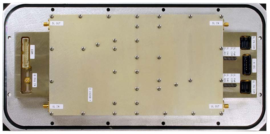
EZZ6138
Sep 21, 2011Channelized Signal Booster
Equipment Class
TNB - Licensed Non-Broadcast Station Transmitter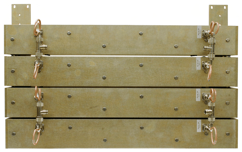
EZZ61170A
Mar 01, 2010Channelized Signal Booster
Equipment Class
TNB - Licensed Non-Broadcast Station Transmitter
EZZ5PI616550
Sep 21, 2006SIGNAL BOOSTER II (SB II)
Equipment Class
TNB - Licensed Non-Broadcast Station Transmitter