EZZ5PI031202SIGNAL BOOSTER TWO-WAY
Bird Technologies Group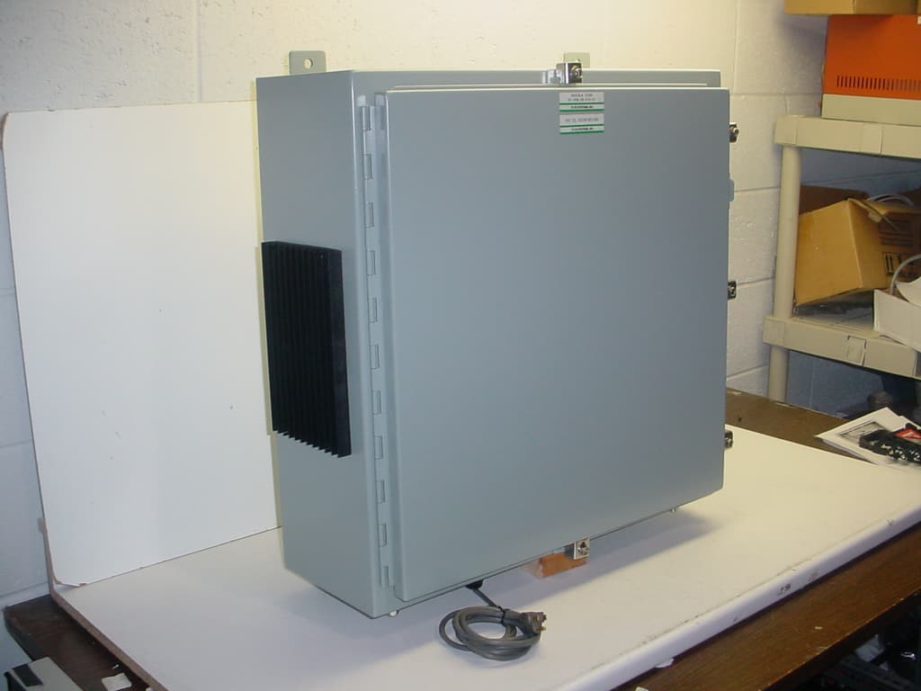
Click to zoom
Application Details
- Equipment Class
- TNB - Licensed Non-Broadcast Station Transmitter
- Date of Grant
- Jan 29, 2004
- Application Purpose
- Original Equipment
- Date of Application
- Jan 29, 2004
- Equipment Note
- SIGNAL BOOSTER TWO-WAY
- Frequency Range
- 851.00000000 - 869.00000000
- Company
- Bird Technologies Group
- Country
- United States
Documents & Files
Document Text
Text extracted from the exhibit documents filed with the FCC. Open a document above to read the original.
Users Manual
61-89A-50-A18-G1-UserMan page 1 of 20 TX RX Systems Inc. Manual 7-9352 (version 4) 01/27/04 Page 1 7-9352-4 Installation and Setup Manual for the Two-Way Signal Booster System Model Number 61-89A-50-A18-G1 First Printing: December 2003 Ve r si o n N u m b e rVe r s i o n D a t e 112/11/00 201/15/04 301/26/04 401/27/04 Part No. Copyright (c) 2003 TX RX Systems, Inc. 61-89A-50-A18-G1-UserMan page 2 of 20 TX RX Systems Inc. Manual 7-9352 (version 4) 01/27/04 Page 2 CAUTION or ATTENTION High VoltageElectrical Shock Hazard Hot Surface ESD Electrostatic Discharge Use Safety Glasses Important Information Symbols Commonly Used Warranty Disclaimer This warranty applies for one year from shipping date. TX RX SYSTEMS INC. warrants its products to be free from defects in material and workmanship at the time of shipment. Our obligation under warranty is limited to replacement or repair at our option, of any such products (with the exception of tubes) which shall have been defective at the time of manufacture. TX RX SYSTEMS INC. reserves the right to replace with merchandise of equal performance although not identical in every way to that originally sold. TX RX SYSTEMS INC. is not liable for damage caused by lightning or other natural disasters. No product will be accepted for repair or replacement without our prior written approval. All Shipping charges on returned products must be prepaid by the purchaser. TX RX SYSTEMS INC. shall in no event be liable for consequential damages, installation costs or expenses of any nature resulting from the purchase or use of products, whether or not they are used in accordance with instructions. This warranty is in lieu of all other warran- ties, either expressed or implied, including any implied warranty of merchantability or of fitness. No representative is authorized to assume for TX RX SYSTEMS INC. any other liability or warranty than set forth above in connection with our products or services. Product part numbering in photographs and drawings is accurate at time of printing. Part number labels on TX RX products supercede part numbers given within this manual. 61-89A-50-A18-G1-UserMan page 3 of 20 TX RX Systems Inc. Manual 7-9352 (version 4) 01/27/04 Page 3 For Class A Unintentional Radiators This equipment has been tested and found to comply with the limits for a Class A digital device, pursuant to part 15 of the FCC rules. These limits are designed to provide reasonable protection against harmful inter- ference when the equipment is operated in a commercial environment. This equipment generates, uses, and can radiate radio frequency energy and, if not installed and used in accordance with the instruction manual, may cause harmful interference to radio communications. Operation of this equipment in a resi- dential area is likely to cause harmful interference in which case the user will be required to correct the interference at his own expense. Changes or modifications not expressly approved by TX RX System Inc. could void the user’s authority to operate the equipment. WARNING This device complies with Part 15 of the FCC Rules. Operation is subject to the following two conditions: (1) this device may not cause harmful interference and (2) this device must accept any interference received, including interference that may cause undesired operation. To satisfy FCC RF exposure requirements for mobile trans- mitting devices, a separation distance of 1.0 Meters or more should be maintained between the UPLINK antenna of this device and persons during device operation. To satisfy FCC RF exposure requirements for mobile transmitting devices, a separation distance of 0.2 Meters or more should be main- tained between the DOWNLINK antenna of this device and persons during device operation. To ensure compliance, operations at closer than these distances is not recom- mended. The antenna used for this transmitter must not be co-located in conjunction with any other antenna or transmitter. WARNING 61-89A-50-A18-G1-UserMan page 4 of 20 TX RX Systems Inc. Manual 7-9352 (version 4) 01/27/04 Page 4 Antenna System Installation The antenna or signal distribution system consists of two branches. An uplink branch typically uses an outdoor mounted, unidirectional gain antenna such as a yagi and a downlink signal radiating system consisting of a network of zero-gain whip antennas or lengths of radiating cable usually mounted inside of the structure. Even though the antenna system may not be supplied or installed by TX RX Systems. The following points need to be observed because both the safety of the user and proper system performance depend on them. 1) Antenna system installation should only be performed by qualified techni- cal personnel. 2) The following instructions for your safety describe antenna installation guidelines based on FCC Maximum RF Exposure Compliance require- ments. 3) The uplink antenna is usually mounted outside and exchanges signals with the repeater base station or donor site. It is typically mounted perma- nently-attached to the building wall or roof. The gain of this antenna should NOT exceed 10 dB. Only qualified personnel should have access to the antenna and under normal operating conditions, no one should be able to touch or approach it within 1 meter (40 inches). 4) The downlink or in-building signal distribution system is connected to the downlink booster port using coaxial cable. The distribution system may use radiating coaxial cable or a network 1/4 wave whip antennas whose gain does not exceed 0 dB for any radiator. These antennas should be installed so that the user cannot approach any closer than 0.2 meters (8 inches) from the antenna. 61-89A-50-A18-G1-UserMan page 5 of 20 TX RX Systems Inc. Manual 7-9352 (version 4) 01/27/04 Page 5 Table of Contents Specifications6 General Description6 Note About Output Power Rating8 Installation8 Cautionary Note8 Pre-RF Connection Tests9 Test Equipment9 Antenna Isolation9 Procedure for Measuring Antenna Isolati…
Text truncated - open the document above for the full version.
External Photos
ANNEX 2 – EXTERNAL PHOTOGRAPHS TX RX Systems, Inc. Signal Booster 2, Model 61-89A-50-A18-G1 FCC ID: EZZ5PI031202 IC: 1940A-PI031202 A2 - 1 ANNEX 2 – EXTERNAL PHOTOGRAPHS TX RX Systems, Inc. Signal Booster 2, Model 61-89A-50-A18-G1 FCC ID: EZZ5PI031202 IC: 1940A-PI031202 A2 - 2 ANNEX 2 – EXTERNAL PHOTOGRAPHS TX RX Systems, Inc. Signal Booster 2, Model 61-89A-50-A18-G1 FCC ID: EZZ5PI031202 IC: 1940A-PI031202 A2 - 3 ANNEX 2 – EXTERNAL PHOTOGRAPHS TX RX Systems, Inc. Signal Booster 2, Model 61-89A-50-A18-G1 FCC ID: EZZ5PI031202 IC: 1940A-PI031202 A2 - 4 ANNEX 2 – EXTERNAL PHOTOGRAPHS TX RX Systems, Inc. Signal Booster 2, Model 61-89A-50-A18-G1 FCC ID: EZZ5PI031202 IC: 1940A-PI031202 A2 - 5
ID Label/Location Info
61-89A-50-A18-G1-LabelLoc page 1 of 2 TX RX SYSTEMS, INC. SERIAL # 3330E 61-89A-50-A18-G1 TX RX SYSTEMS, INC. FCC ID: EZZ5PI031202 TX RX SYSTEMS, INC. SERIAL # 3330E SERIAL # 3330E 61-89A-50-A18-G161-89A-50-A18-G1 TX RX SYSTEMS, INC. FCC ID: EZZ5PI031202 FCC ID: EZZ5PI031202 11" 2.25" 61-89A-50-A18-G1-LabelLoc page 2 of 2 TX RX SYSTEMS, INC. SERIAL # 3330E 61-89A-50-A18-G1 TX RX SYSTEMS, INC. IC: 1940A-PI031202 TX RX SYSTEMS, INC. SERIAL # 3330E SERIAL # 3330E 61-89A-50-A18-G161-89A-50-A18-G1 TX RX SYSTEMS, INC. IC: 1940A-PI031202 IC: 1940A-PI031202 11" 2.25"
ID Label/Location Info
61-89A-50-A18-G1-LabelSmpl page 1 of 1 TX RX SYSTEMS, INC. IC: 1940A-PI031202 TX RX SYSTEMS, INC. FCC ID: EZZ5PI031202 Sample of FCC Label Sample of IC Label
Internal Photos
ANNEX 3 – INTERNAL PHOTOGRAPHS TX RX Systems, Inc. Signal Booster 2, Model 61-89A-50-A18-G1 FCC ID: EZZ5PI031202 IC: 1940A-PI031202 A2 - 1 ANNEX 3 – INTERNAL PHOTOGRAPHS TX RX Systems, Inc. Signal Booster 2, Model 61-89A-50-A18-G1 FCC ID: EZZ5PI031202 IC: 1940A-PI031202 A2 - 2 ANNEX 3 – INTERNAL PHOTOGRAPHS TX RX Systems, Inc. Signal Booster 2, Model 61-89A-50-A18-G1 FCC ID: EZZ5PI031202 IC: 1940A-PI031202 A2 - 3 ANNEX 3 – INTERNAL PHOTOGRAPHS TX RX Systems, Inc. Signal Booster 2, Model 61-89A-50-A18-G1 FCC ID: EZZ5PI031202 IC: 1940A-PI031202 A2 - 4 ANNEX 3 – INTERNAL PHOTOGRAPHS TX RX Systems, Inc. Signal Booster 2, Model 61-89A-50-A18-G1 FCC ID: EZZ5PI031202 IC: 1940A-PI031202 A2 - 5 ANNEX 3 – INTERNAL PHOTOGRAPHS TX RX Systems, Inc. Signal Booster 2, Model 61-89A-50-A18-G1 FCC ID: EZZ5PI031202 IC: 1940A-PI031202 A2 - 6 ANNEX 3 – INTERNAL PHOTOGRAPHS TX RX Systems, Inc. Signal Booster 2, Model 61-89A-50-A18-G1 FCC ID: EZZ5PI031202 IC: 1940A-PI031202 A2 - 7 ANNEX 3 – INTERNAL PHOTOGRAPHS TX RX Systems, Inc. Signal Booster 2, Model 61-89A-50-A18-G1 FCC ID: EZZ5PI031202 IC: 1940A-PI031202 A2 - 8 ANNEX 3 – INTERNAL PHOTOGRAPHS TX RX Systems, Inc. Signal Booster 2, Model 61-89A-50-A18-G1 FCC ID: EZZ5PI031202 IC: 1940A-PI031202 A2 - 9 ANNEX 3 – INTERNAL PHOTOGRAPHS TX RX Systems, Inc. Signal Booster 2, Model 61-89A-50-A18-G1 FCC ID: EZZ5PI031202 IC: 1940A-PI031202 A2 - 10 ANNEX 3 – INTERNAL PHOTOGRAPHS TX RX Systems, Inc. Signal Booster 2, Model 61-89A-50-A18-G1 FCC ID: EZZ5PI031202 IC: 1940A-PI031202 A2 - 11 ANNEX 3 – INTERNAL PHOTOGRAPHS TX RX Systems, Inc. Signal Booster 2, Model 61-89A-50-A18-G1 FCC ID: EZZ5PI031202 IC: 1940A-PI031202 A2 - 12 ANNEX 3 – INTERNAL PHOTOGRAPHS TX RX Systems, Inc. Signal Booster 2, Model 61-89A-50-A18-G1 FCC ID: EZZ5PI031202 IC: 1940A-PI031202 A2 - 13 ANNEX 3 – INTERNAL PHOTOGRAPHS TX RX Systems, Inc. Signal Booster 2, Model 61-89A-50-A18-G1 FCC ID: EZZ5PI031202 IC: 1940A-PI031202 A2 - 14 ANNEX 3 – INTERNAL PHOTOGRAPHS TX RX Systems, Inc. Signal Booster 2, Model 61-89A-50-A18-G1 FCC ID: EZZ5PI031202 IC: 1940A-PI031202 A2 - 15 ANNEX 3 – INTERNAL PHOTOGRAPHS TX RX Systems, Inc. Signal Booster 2, Model 61-89A-50-A18-G1 FCC ID: EZZ5PI031202 IC: 1940A-PI031202 A2 - 16 ANNEX 3 – INTERNAL PHOTOGRAPHS TX RX Systems, Inc. Signal Booster 2, Model 61-89A-50-A18-G1 FCC ID: EZZ5PI031202 IC: 1940A-PI031202 A2 - 17 ANNEX 3 – INTERNAL PHOTOGRAPHS TX RX Systems, Inc. Signal Booster 2, Model 61-89A-50-A18-G1 FCC ID: EZZ5PI031202 IC: 1940A-PI031202 A2 - 18 ANNEX 3 – INTERNAL PHOTOGRAPHS TX RX Systems, Inc. Signal Booster 2, Model 61-89A-50-A18-G1 FCC ID: EZZ5PI031202 IC: 1940A-PI031202 A2 - 19 ANNEX 3 – INTERNAL PHOTOGRAPHS TX RX Systems, Inc. Signal Booster 2, Model 61-89A-50-A18-G1 FCC ID: EZZ5PI031202 IC: 1940A-PI031202 A2 - 20 ANNEX 3 – INTERNAL PHOTOGRAPHS TX RX Systems, Inc. Signal Booster 2, Model 61-89A-50-A18-G1 FCC ID: EZZ5PI031202 IC: 1940A-PI031202 A2 - 21 ANNEX 3 – INTERNAL PHOTOGRAPHS TX RX Systems, Inc. Signal Booster 2, Model 61-89A-50-A18-G1 FCC ID: EZZ5PI031202 IC: 1940A-PI031202 A2 - 22 ANNEX 3 – INTERNAL PHOTOGRAPHS TX RX Systems, Inc. Signal Booster 2, Model 61-89A-50-A18-G1 FCC ID: EZZ5PI031202 IC: 1940A-PI031202 A2 - 23 ANNEX 3 – INTERNAL PHOTOGRAPHS TX RX Systems, Inc. Signal Booster 2, Model 61-89A-50-A18-G1 FCC ID: EZZ5PI031202 IC: 1940A-PI031202 A2 - 24 ANNEX 3 – INTERNAL PHOTOGRAPHS TX RX Systems, Inc. Signal Booster 2, Model 61-89A-50-A18-G1 FCC ID: EZZ5PI031202 IC: 1940A-PI031202 A2 - 25 ANNEX 3 – INTERNAL PHOTOGRAPHS TX RX Systems, Inc. Signal Booster 2, Model 61-89A-50-A18-G1 FCC ID: EZZ5PI031202 IC: 1940A-PI031202 A2 - 26 ANNEX 3 – INTERNAL PHOTOGRAPHS TX RX Systems, Inc. Signal Booster 2, Model 61-89A-50-A18-G1 FCC ID: EZZ5PI031202 IC: 1940A-PI031202 A2 - 27 ANNEX 3 – INTERNAL PHOTOGRAPHS TX RX Systems, Inc. Signal Booster 2, Model 61-89A-50-A18-G1 FCC ID: EZZ5PI031202 IC: 1940A-PI031202 A2 - 28 ANNEX 3 – INTERNAL PHOTOGRAPHS TX RX Systems, Inc. Signal Booster 2, Model 61-89A-50-A18-G1 FCC ID: EZZ5PI031202 IC: 1940A-PI031202 A2 - 29 ANNEX 3 – INTERNAL PHOTOGRAPHS TX RX Systems, Inc. Signal Booster 2, Model 61-89A-50-A18-G1 FCC ID: EZZ5PI031202 IC: 1940A-PI031202 A2 - 30 ANNEX 3 – INTERNAL PHOTOGRAPHS TX RX Systems, Inc. Signal Booster 2, Model 61-89A-50-A18-G1 FCC ID: EZZ5PI031202 IC: 1940A-PI031202 A2 - 31 ANNEX 3 – INTERNAL PHOTOGRAPHS TX RX Systems, Inc. Signal Booster 2, Model 61-89A-50-A18-G1 FCC ID: EZZ5PI031202 IC: 1940A-PI031202 A2 - 32 ANNEX 3 – INTERNAL PHOTOGRAPHS TX RX Systems, Inc. Signal Booster 2, Model 61-89A-50-A18-G1 FCC ID: EZZ5PI031202 IC: 1940A-PI031202 A2 - 33 ANNEX 3 – INTERNAL PHOTOGRAPHS TX RX Systems, Inc. Signal Booster 2, Model 61-89A-50-A18-G1 FCC ID: EZZ5PI031202 IC: 1940A-PI031202 A2 - 34 ANNEX 3 – INTERNAL PHOTOGRAPHS TX RX Systems, Inc. Signal Booster 2, Model 61-89A-50-A18-G1 FCC ID: EZZ5PI031202 IC: 1940A-PI031202 A2 - 35 ANNEX 3 – INTERNAL PHOTOGRAPHS TX RX Systems, Inc. Signal Booster 2, Model 61-89A-50-A18-G1 FCC ID: EZZ5PI031202 IC: 1940A-PI031202 A2 - 36 ANNEX 3 – INTERNAL PHOTOGRAPHS TX RX Systems, Inc. Signal Booster 2, Model 61-89A-50-A18-G1 FCC ID: EZZ5PI031202 IC: 1940A-PI031202 A2 - 37 ANNEX 3 – INTERNAL PHOTOGRAPHS TX RX Systems, Inc. Signal Booster 2, Model 61-89A-50-A18-G1 FCC ID: EZZ5PI031202 IC: 1940A-PI031202 A2 - 38 ANNEX 3 – INTERNAL PHOTOGRAPHS TX RX Systems, Inc. Signal Booster 2, Model 61-89A-50-A18-G1 FCC ID: EZZ5PI031202 IC: 1940A-PI031202 A2 - 39 ANNEX 3 – INTERNAL PHOTOGRAPHS TX RX Systems, Inc. Signal Booster 2, Model 61-89A-50-A18-G1 FCC ID: EZZ5PI031202 IC: 1940A-PI031202 A2 - 40 ANNEX 3 – INTERNAL PHOTOGRAPHS TX RX Systems, Inc. Signal Booster 2, Model 61-89A-50-A18-G1 FCC ID: EZZ5PI031202 IC: 1940A-PI031202 A2 - 41 ANNEX 3 – INTERNAL PHOTOGRAPHS TX RX Systems, Inc. Signal Booster 2, Model 61-89A-50-A18-G1 FCC ID: EZZ5PI031202 IC: 1940A-PI031202 A2 - 42
Parts List/Tune Up Info
January 29, 2004 TX RX Systems, Inc Tim co c/o Ultratech 3000 Bristol Circle O akville, O ntario Canada L6H 6G4 Dear Sir, This letter is in response to your request for tuning instructions to accompany the application for type certification for signal booster model 61- 89A-50-A18-G1, FCC ID: EZZ5PI031202. It is our position that there is NO tuning of any of the components of this device required for normal operation or as part of normal maintenance. This device uses broadband, amplifier circuitry that requires no tuning adjustments. It contains no frequency controlling circuitry. The only components that have tuning elements are the two duplexers that are used to couple the two amplifier branches to common inputs or outputs. The duplexer consists of a pair of complex combline bandpass filters that can only be tuned at the factory. These filters are tuned following a complex procedure which requires the use of a vector network analyzer capable of displaying transmission and reflection scattering parameters on a Smith- Chart display. This type of equipment is not normally available to field service technicians or engineers and therefore limits adjustments to the factory environment. The filters are passive devices of robust metal construction and w ill hold there tuning characteristics for the life of the equipment unless they are physically damaged. Such damage would most likely render the booster inoperable. We therefore respectfully request that the requirement for tuning instructions be waved for this unit. Sincerely, Dennis G. Hohman Engineering Services Manager TX RX Systems, Inc 8625 Industrial Parkway Angola, NY 14006 716.549.4700 Fax 716.549.4772
Test Report
Signal Booster 2 Model No.: 61-89A-50-A18-G1 FCC ID: EZZ5PI031202 Applicant: TX RX Systems, Inc. 8625 Industrial Parkway Angola, NY 14006 USA Tested in Accordance With Federal Communications Commission (FCC) 47 CFR, Parts 2 and 90 (Subpart I) UltraTech's File No.: TXRX-008FCC90 This Test report is Issued under the Authority of Tri M. Luu, Professional Engineer, Vice President of Engineering UltraTech Group of Labs Date: January 21, 2004 Report Prepared by: Dan Huynh Issued Date: January 21, 2004 Tested by: Hung Trinh, EMI/RFI Technician Test Dates: January 4-7, 2004 The results in this Test Report apply only to the sample(s) tested, and the sample tested is randomly selected. This report must not be used by the client to claim product endorsement by NVLAP or any agency of the US Government. UltraTech 3000 Bristol Circle, Oakville, Ontario, Canada, L6H 6G4 Tel.: (905) 829-1570 Fax.: (905) 829-8050 Website: www.ultratech-labs.com , Email: [email protected], Email: [email protected] 2 31040/SIT C-1376 46390-2049 200093-0 SL2-IN-E-1119R 00-034 FCC Parts 2 and 90 (Subpart I), Non-Broadcast Radio Transceivers Contents i Signal Booster 2, Model 61-89A-50-A18-G1 FCC ID: EZZ5PI031202 ULTRATECH GROUP OF LABS File #: TXRX-008FCC90 3000 Bristol Circle, Oakville, Ontario, Canada L6H 6G4 January 21, 2004 Tel. #: 905-829-1570, Fax. #: 905-829-8050, Email: [email protected] , Website: http://www.ultratech-labs.com All test results contained in this engineering test report are traceable to National Institute of Standards and Technology (NIST) TABLE OF CONTENTS EXHIBIT 1. SUBMITTAL CHECK LIST ................................................................................................................................................... 1 EXHIBIT 2. INTRODUCTION .................................................................................................................................................................... 2 2.1. SCOPE...................................................................................................................................................................................................... 2 2.2. RELATED SUBMITTAL(S)/GRANT(S) ................................................................................................................................................ 2 2.3. NORMATIVE REFERENCES ................................................................................................................................................................ 2 EXHIBIT 3. PERFORMANCE ASSESSMENT.......................................................................................................................................... 3 3.1. CLIENT INFORMATION ....................................................................................................................................................................... 3 3.2. EQUIPMENT UNDER TEST (EUT) INFORMATION .......................................................................................................................... 3 3.3. EUT’S TECHNICAL SPECIFICATIONS ............................................................................................................................................... 4 3.4. LIST OF EUT’S PORTS .......................................................................................................................................................................... 5 3.5. ANCILLARY EQUIPMENT ................................................................................................................................................................... 5 EXHIBIT 4. EUT OPERATING CONDITIONS AND CONFIGURATIONS DURING TESTS ........................................................... 6 4.1. CLIMATE TEST CONDITIONS............................................................................................................................................................. 6 4.2. OPERATIONAL TEST CONDITIONS & ARRANGEMENT FOR TEST SIGNALS .......................................................................... 6 EXHIBIT 5. SUMMARY OF TEST RESULTS .......................................................................................................................................... 7 5.1. LOCATION OF TESTS ........................................................................................................................................................................... 7 5.2. APPLICABILITY & SUMMARY OF EMC EMISSION TEST RESULTS ........................................................................................... 7 5.3. MODIFICATIONS INCORPORATED IN THE EUT FOR COMPLIANCE PURPOSES..................................................................... 7 5.4. DEVIATION OF STANDARD TEST PROCEDURES .......................................................................................................................... 7 EXHIBIT 6. MEASUREMENTS, EXAMINATIONS & TEST DATA FOR EMC EMISSIONS........................................................... 8 6.1. TEST PROCEDURES.............................................................................................................................................................................. 8 6.2. MEASUREMENT UNCERTAINTIES.................................................................................................................................................... 8 6.3. MEASUREMENT EQUIPMENT USED................................................................................................................................................. 8 6.4. ESSENTIAL/PRIMARY FUNCTIONS AS DECLARED BY THE MANUFACTURER...................................................................... 8 6.5. RF POWER OUTPUT & INTERMODULATION [§§ 2.1046 & 90.205]............................................................................................... 9 6.6. RF EXPOSURE REQUIREMENTS [§§ 1.1310 & 2.1091] ...........................…
Text truncated - open the document above for the full version.
Test Setup Photos
ANNEX 1 - TEST SETUP PHOTOGRAPHS TX RX Systems, Inc. Signal Booster 2, Model 61-89A-50-A18-G1 FCC ID: EZZ5PI031202 A1 - 1 Radiated Emissions at 3 Meters Distance ANNEX 1 - TEST SETUP PHOTOGRAPHS TX RX Systems, Inc. Signal Booster 2, Model 61-89A-50-A18-G1 FCC ID: EZZ5PI031202 A1 - 2 Radiated Emissions at 3 Meters Distance
Contact Information
Applicant
Amy Sanvido(RF Engineer)
Test Firm
UltraTech Engineering Labs Inc.Victor Kee
Technical Specifications
| # | Rule Parts | Frequency Range | Power Output | Emission |
|---|---|---|---|---|
| 6 | 9 | 851 MHz - 869 MHz | 1.6 W | G3E |
Other Applications from Bird Technologies Group
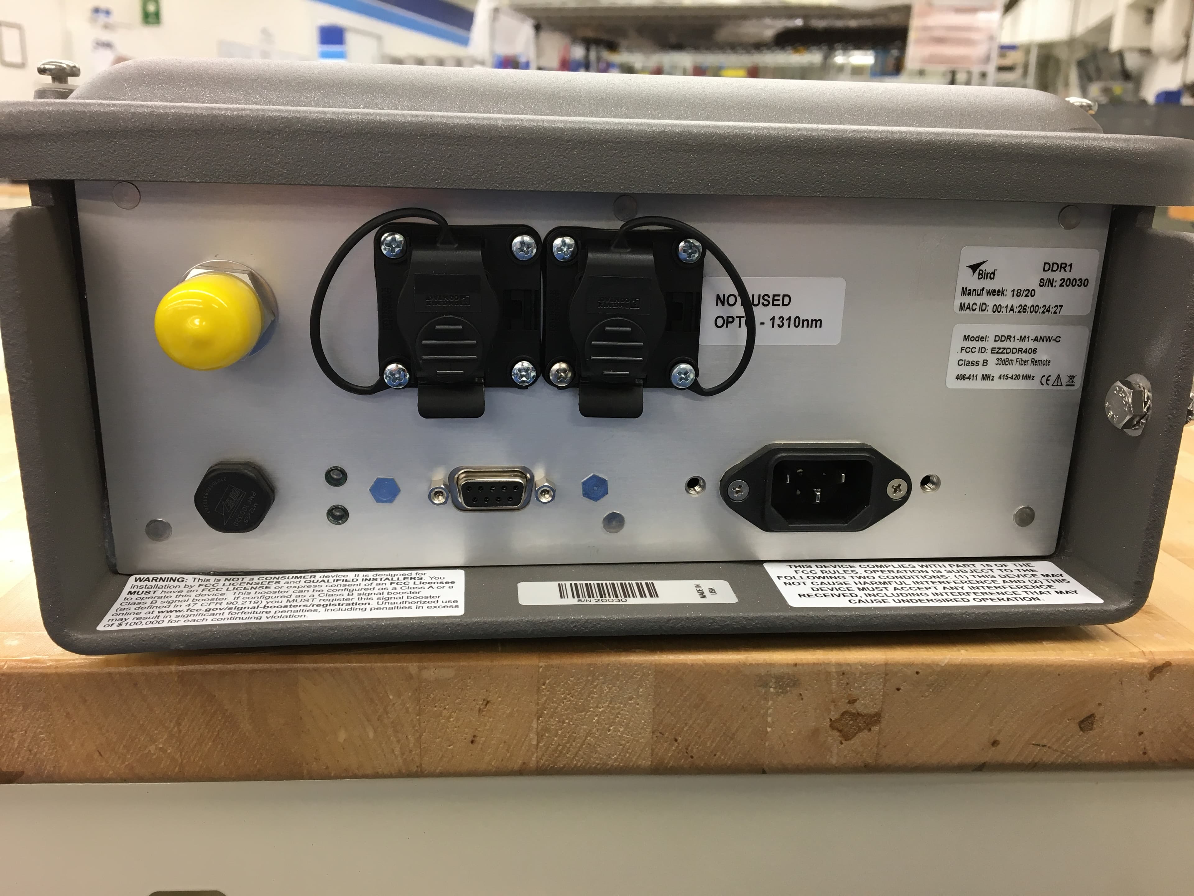
EZZDDR406
Jun 24, 2020DDR Low Band UHF Remote
Equipment Class
B9B - Part 90 Class B Industrial Booster (non-SMR)
EZZ61470
May 19, 2015UHF Digital Signal Booster
Equipment Class
B9A - Part 90 Class A Industrial Booster (non-SMR)
EZZ61470A
May 18, 2015UHF Digital Signal Booster
Equipment Class
B9A - Part 90 Class A Industrial Booster (non-SMR)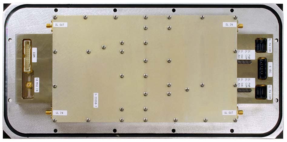
EZZ6138
Sep 21, 2011Channelized Signal Booster
Equipment Class
TNB - Licensed Non-Broadcast Station Transmitter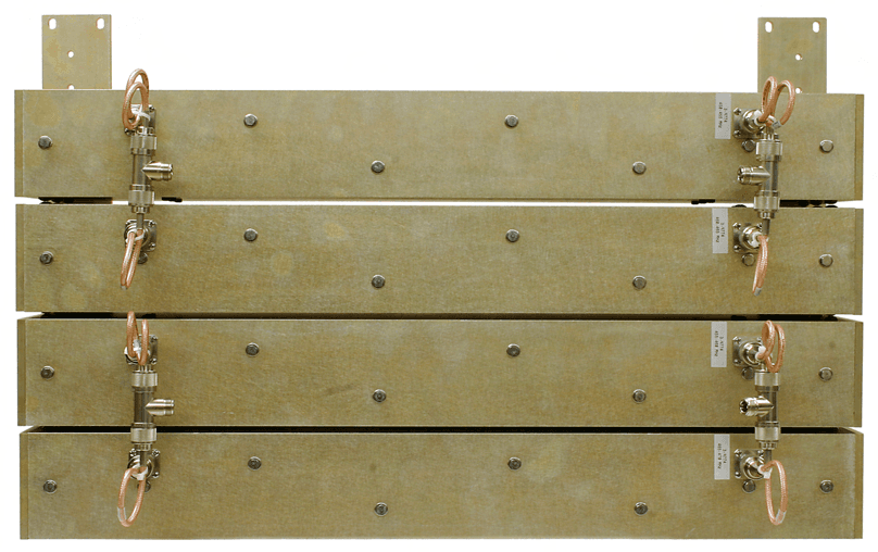
EZZ61170A
Mar 01, 2010Channelized Signal Booster
Equipment Class
TNB - Licensed Non-Broadcast Station Transmitter