EZZ5PI616550SIGNAL BOOSTER II (SB II)
Bird Technologies Group
Click to zoom
Application Details
- Equipment Class
- TNB - Licensed Non-Broadcast Station Transmitter
- Date of Grant
- Sep 21, 2006
- Application Purpose
- Original Equipment
- Date of Application
- Sep 21, 2006
- Equipment Note
- SIGNAL BOOSTER II (SB II)
- Frequency Range
- 406.10000000 - 430.00000000
- Company
- Bird Technologies Group
- Country
- United States
Documents & Files
Document Text
Text extracted from the exhibit documents filed with the FCC. Open a document above to read the original.
Cover Letter(s)
August 28, 2006 TIMCO ENGINEERING INC. P.O. Box 370 849 N.W. State Road 45 Newberry, Florida USA, 32669 Subject: Equipment Authorization under FCC 47 CFR, Parts 2 and 90 (Subpart I) - Non- Broadcast Radio Transceivers Operating in the Frequency band 406-430 MHz (12.5 kHz and 25 kHz Channel Spacings) Applicant: TX RX Systems, Inc. Product: Signal Booster II Model: 61-65-50 FCC ID: EZZ5PI616550 Dear Sir/Madam, As appointed agent for TX RX Systems, Inc., we would like to submit the application to Timco Engineering Inc. for FCC Certification of the above Product. Please review all files uploaded to TIMCO Upload Electronic Filing Site. If you have any queries, please do not hesitate to contact us Yours truly, Tri Minh Luu, P. Eng., V.P., Engineering UltraTech Group of Labs Ultratech’s Accreditations: 0685 31040/SIT C-1376 46390-2049 200093-0 SL2-IN-E-1119R 3000 Bristol Circle, Oakville, Ontario, Canada L6H 6G4 Tel.: (905) 829-1570 Fax.: (905) 829-8050 Website: www.ultratech-labs.com Email: [email protected]
Cover Letter(s)
Federal Communications Commission Authorization and Evaluation Division Confidentiality Request regarding application for certification of FCC ID: EZZ5PI616550. Pursuant to Sections 0.457 and 0.459 of the Commission’s Rules, we hereby request confidential treatment of information accompanying this application as outlined below: Exhibit Type File Name Block Diagram 61-65-50--BlkDia_CONFIDENTIAL.pdf Schematics 61-65-50--Schem_CONFIDENTIAL.pdf Parts List 61-65-50--PartsLst_CONFIDENTIAL.pdf Operational Description 61-65-50--OpDes_CONFIDENTIAL.pdf Operational Description 61-65-50 Gain Configurations_CONFIDENTIAL.pdf The above materials contain trade secrets and proprietary information not customarily released to the public. The public disclosure of these materials may be harmful to the applicant and provide unjustified benefits to its competitors. The applicant understands that pursuant to Section 0.457 of the Rules, disclosure of this application and all accompanying documentation will not be made before the date of the Grant for this application. Sincerely, William J. Aquino, Technical Documentation Specialist
External Photos
61-65-50 ExtPhot page 2 of 19 Cabinet Rear View 61-65-50 ExtPhot page 3 of 19 Cabinet Right Side View Cabinet Left Side View Cabinet Bottom View Cabinet Top View
ID Label/Location Info
61-65-50-XXX-XX LabelSmpl page 1 of 1 TX RX SYSTEMS, INC. FCC ID: EZZ5PI616550 TX RX SYSTEMS, INC. IC: 1940A-PI616550 Sample of FCC Label Sample of IC Label 61-65-50-XXX-XX LabelLoc page 1 of 2 TX RX SYSTEMS, INC. FCC ID: EZZ5PI616550 TX RX SYSTEMS, INC. SERIAL # XXXXX 61-65-50 TX RX SYSTEMS, INC. FCC ID: EZZ5PI616550 FCC ID: EZZ5PI616550 TX RX SYSTEMS, INC. SERIAL # XXXXX SERIAL # XXXXX 61-65-5061-65-50 2.25" 14" 61-65-50-XXX-XX LabelLoc page 2 of 2 TX RX SYSTEMS, INC. IC: 1940A-PI616550 TX RX SYSTEMS, INC. SERIAL # XXXXX 61-65-50 TX RX SYSTEMS, INC. IC: 1940A-PI616550 IC: 1940A-PI616550 TX RX SYSTEMS, INC. SERIAL # XXXXX SERIAL # XXXXX 61-65-5061-65-50 2.25" 14"
Internal Photos
61-65-50 ExtPhot page 1 of 19 61-65-50-A5.0-G1 Two-Way Signal Booster System Cabinet Inside View 61-65-50 ExtPhot page 4 of 19 8-20667 Power Supply Assembly 61-65-50 ExtPhot page 5 of 19 3-10917 Filter Assembly 61-65-50 ExtPhot page 6 of 19 3-4823 Filter Assembly 61-65-50 ExtPhot page 7 of 19 3-20807 Uplink and Downlink Power Amplifier Assembly 61-65-50 ExtPhot page 8 of 19 3-19576 Mid-Level Amplifier Card 61-65-50 ExtPhot page 9 of 19 3-19935 Low-Level Amplifer Assembly 61-65-50 ExtPhot page 10 of 19 3-21035 Half-Gain Low-Level Amplifier Assembly 61-65-50 ExtPhot page 11 of 19 3-20208 Attenuator Card 61-65-50 ExtPhot page 12 of 19 3-19832 Controller Card 61-65-50 ExtPhot page 13 of 19 3-19833 Power Distribution Card 61-65-50 ExtPhot page 14 of 19 3-16956 Signal Sampler Assembly 61-65-50 ExtPhot page 15 of 19 3-21279 Isolator Asembly 61-65-50 ExtPhot page 16 of 19 8-20847 EMI/RFI Filter Assembly 61-65-50 ExtPhot page 17 of 19 3-20197 Power Junction Box 61-65-50 ExtPhot page 18 of 19 3-21182 Card Cage 61-65-50 ExtPhot page 19 of 19 3-19831 Display Panel Assembly 61-65-50 IntPhot page 1 of 10 3-20807 Power Amplifier Assembly Front PCB View 3-20807 Power Amplifier Assembly Back PCB View 61-65-50 IntPhot page 2 of 10 3-19576 Mid-Level Amplifier Card Front PCB View 3-19576 Mid-Level Amplifier Card Back PCB View 61-65-50 IntPhot page 3 of 10 3-19935 Low-Level Amplifier Assembly Front PCB View 3-19935 Low-Level Amplifier Assembly Back PCB View 61-65-50 IntPhot page 4 of 10 3-21035 Half-Gain Low-Level Amplifier Assembly Front PCB View 3-21035 Half-Gain Low-Level Amplifier Assembly Back PCB View 61-65-50 IntPhot page 5 of 10 3-20208 Attenuator Card Front PCB View 3-20208 Attenuator Card Back PCB View 61-65-50 IntPhot page 6 of 10 3-19832 Control Card Front PCB View 3-19832 Control Card Back PCB View 61-65-50 IntPhot page 7 of 10 3-19833 Power Distribution Card Front PCB View 3-19833 Power Distribution Card Back PCB View 61-65-50 IntPhot page 8 of 10 3-19826 BackPlane Circuit Board Front PCB View 3-19826 BackPlane Circuit Board Rear PCB View 61-65-50 IntPhot page 9 of 10 3-20189 DC - DC Converter Board Front PCB View 3-20189 DC - DC Converter Board Back PCB View 61-65-50 IntPhot page 10 of 10 3-19708 Display Circuit Board Front PCB View 3-19708 Display Circuit Board Back PCB View
Parts List/Tune Up Info
TXRX Systems Inc. Tuning Instructions for TXRX 61-65-50 08/28/06 Page 1 GENERAL DESCRIPTION Tuning instructions are provided in support of field service activities. It is assumed that the procedures listed in this instruction will be carried out by a qualified electronics technician observing all stan- dard safety practices. The amplifier assemblies used in the model 61-65- 50 signal booster is of sufficient bandwidth to cover the entire range of operation. Tuning is not required. The individual filters used in the duplexer are passive devices of rugged electrical and mechanical design. They are tuned at the factory for the original design requirements and require no adjustment or maintenance. These devices will stay properly tuned unless they have been physi- cally damaged or are tampered with. Combline preselector filters provide the input and output selectivity for the system. These filters have a care- fully shaped response curve that passes a number of contiguous communication channels. Test Equipment A two channel network analyzer that simulta- neously displays both transmission and reflection is best for properly tuning a preselector. A single channel tracking generator/spectrum analyzer combination may be adequate but is not accurate enough to verify factory specifications. A return loss bridge would also be required when using a tracking generator. Skill and experience are also needed and the personnel doing the work should be thoroughly familiar with the use of the network analyzer. A Hewlett Packard 8752B or equivalent network analyzer is recommended. Preselector Tuning The tuning rods are the thin rods protruding from the top of the filter. The inner six rods are used to adjust the center frequency of the bandpass filter. The outer two thin rods are used to adjust the notch frequency. The thicker rods are used at the factory to adjust the bandwidth of the filters and these rods should not be adjusted in the field. The following is a general outline of the tuning proce- dure. 1) Connect test equipment as shown in Figure 1. 2) Set the analyzer to the desired center fre- quency and desired bandwidth. 3) Loosen the tuning rod locking nuts. 4) If the preselector is severely out of tune, set the analyzer for 10 dB/div vertical scale on the transmission channel and alternately adjust the six inner tuning rods in pairs working from the center to the end rods for maximum signal at the center frequency. 5) Adjust the two outer tuning rods to set the notching frequency. 6) Repeat steps 4 and 5 tuning to maximize the signal at the center frequency. The response should start to take on the desired shape and symmetry. Setup the analyzer for 1 dB/div (2 dB/div for a tracking generator) on the transmis- sion channel and then re-adjust the rods in the same fashion. Make sure that the return loss curve meets or exceeds the published specifi- cation over the range and is relatively symmetri- cal. Fine adjust the tuning rods to adjust symmetry. 7) Lock all tuning rods after the desired response is obtained. Note that a slight dissymmetry in either the transmission or reflection response may be unavoidable. Analyzer Input Generate Output +30 +40 +20 +10 0 -10 -20 -30 -40 8 Section Combline Bandpass Filter Figure 1: Preselector Tuning. Tuning Instructions for the Model 61-65-50 Signal Booster
Test Report
Signal Booster II Model No.: 61-65-50 FCC ID: EZZ5PI616550 Applicant: TX RX Systems, Inc. 8625 Industrial Parkway Angola, NY 14006 USA Tested in Accordance With Federal Communications Commission (FCC) 47 CFR Parts 2 and 90 (Subpart I) UltraTech's File No.: TXRX-017F90 This Test report is Issued under the Authority of Tri M. Luu, Professional Engineer, Vice President of Engineering UltraTech Group of Labs Date: August 28, 2006 Report Prepared by: Dan Huynh Issued Date: August 28, 2006 Tested by: Hung Trinh, EMI/RFI Technician Test Dates: June 22 - August 8, 2006 The results in this Test Report apply only to the sample(s) tested, and the sample tested is randomly selected. This report must not be used by the client to claim product endorsement by NVLAP or any agency of the US Government. UltraTech 3000 Bristol Circle, Oakville, Ontario, Canada, L6H 6G4 Tel.: (905) 829-1570 Fax: (905) 829-8050 Website: www.ultratech-labs.com , Email: [email protected], Email: [email protected] 0685 31040/SIT C-1376 46390-2049 200093-0 SL2-IN-E-1119R FCC Parts 2 and 90 (Subpart I), Non-Broadcast Radio Transceivers Contents i Signal Booster II, Model 61-65-50 FCC ID: EZZ5PI616550 ULTRATECH GROUP OF LABS File #: TXRX-017F90 3000 Bristol Circle, Oakville, Ontario, Canada L6H 6G4 August 28, 2006 Tel. #: 905-829-1570, Fax. #: 905-829-8050, Email: [email protected] , Website: http://www.ultratech-labs.com All test results contained in this engineering test report are traceable to National Institute of Standards and Technology (NIST) TABLE OF CONTENTS EXHIBIT 1. SUBMITTAL CHECK LIST ..........................................................................................................................................1 EXHIBIT 2. INTRODUCTION ............................................................................................................................................................2 2.1. SCOPE ............................................................................................................................................................................................2 2.2. RELATED SUBMITTAL(S)/GRANT(S).......................................................................................................................................2 2.3. NORMATIVE REFERENCES .......................................................................................................................................................2 EXHIBIT 3. PERFORMANCE ASSESSMENT .................................................................................................................................3 3.1. CLIENT INFORMATION ..............................................................................................................................................................3 3.2. EQUIPMENT UNDER TEST (EUT) INFORMATION.................................................................................................................3 3.3. EUT’S TECHNICAL SPECIFICATIONS......................................................................................................................................4 3.4. LIST OF EUT’S PORTS.................................................................................................................................................................5 3.5. ANCILLARY EQUIPMENT ..........................................................................................................................................................5 3.6. GENERAL TEST SETUP...............................................................................................................................................................5 EXHIBIT 4. EUT OPERATING CONDITIONS AND CONFIGURATIONS DURING TESTS...................................................6 4.1. CLIMATE TEST CONDITIONS ...................................................................................................................................................6 4.2. OPERATIONAL TEST CONDITIONS & ARRANGEMENT FOR TEST SIGNALS.................................................................6 EXHIBIT 5. SUMMARY OF TEST RESULTS..................................................................................................................................7 5.1. LOCATION OF TESTS..................................................................................................................................................................7 5.2. APPLICABILITY & SUMMARY OF EMC EMISSION TEST RESULTS ..................................................................................7 5.3. MODIFICATIONS INCORPORATED IN THE EUT FOR COMPLIANCE PURPOSES............................................................7 EXHIBIT 6. MEASUREMENTS, EXAMINATIONS & TEST DATA FOR EMC EMISSIONS ..................................................8 6.1. TEST PROCEDURES ....................................................................................................................................................................8 6.2. MEASUREMENT UNCERTAINTIES ..........................................................................................................................................8 6.3. MEASUREMENT EQUIPMENT USED .......................................................................................................................................8 6.4. ESSENTIAL/PRIMARY FUNCTIONS AS DECLARED BY THE MANUFACTURER ............................................................8 6.5. RF POWER OUTPUT & INTERMODULATION [§§ 2.1046 & 90.205].................................................................... ..................9 6.6. RF EXPOSURE REQUIREMENTS [§§ 1.1310 & 2.1091].......................................................................................................... 20 6.7. OCCUPIED BANDWIDTH [§ 2.1049] .................................................................................................................................…
Text truncated - open the document above for the full version.
Test Setup Photos
ANNEX 1 - TEST SETUP PHOTOGRAPHS TX RX Systems, Inc. Signal Booster II, Model 61-65-50 FCC ID: EZZ5PI616550 A1 - 1 Radiated Emissions at 3 m Distance ANNEX 1 - TEST SETUP PHOTOGRAPHS TX RX Systems, Inc. Signal Booster II, Model 61-65-50 FCC ID: EZZ5PI616550 A1 - 2 Radiated Emissions at 3 m Distance
Contact Information
Applicant
Amy Sanvido(RF Engineer)
Test Firm
UltraTech Engineering Labs Inc.Tri Luu
Technical Specifications
| # | Rule Parts | Frequency Range | Power Output | Emission | Tolerance |
|---|---|---|---|---|---|
| 3 | 9 | 406.1 MHz - 430 MHz | 1.6 W | G3E | Amp |
Other Applications from Bird Technologies Group
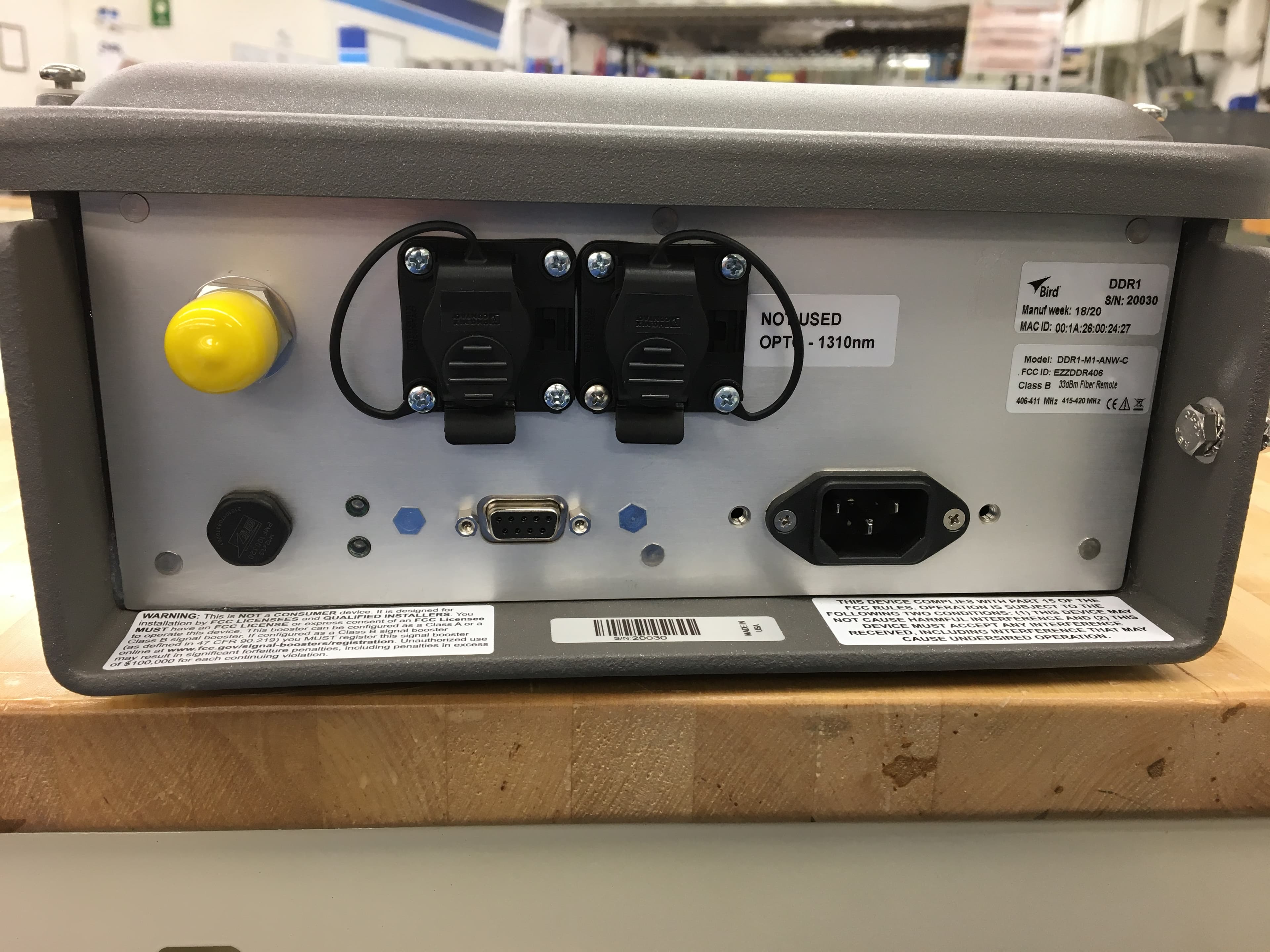
EZZDDR406
Jun 24, 2020DDR Low Band UHF Remote
Equipment Class
B9B - Part 90 Class B Industrial Booster (non-SMR)
EZZ61470
May 19, 2015UHF Digital Signal Booster
Equipment Class
B9A - Part 90 Class A Industrial Booster (non-SMR)
EZZ61470A
May 18, 2015UHF Digital Signal Booster
Equipment Class
B9A - Part 90 Class A Industrial Booster (non-SMR)
EZZ6138
Sep 21, 2011Channelized Signal Booster
Equipment Class
TNB - Licensed Non-Broadcast Station Transmitter
EZZ61170A
Mar 01, 2010Channelized Signal Booster
Equipment Class
TNB - Licensed Non-Broadcast Station Transmitter