EZZ5PI616850SIGAL BOOSTER 2
Bird Technologies Group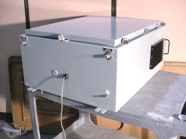
Click to zoom
Application Details
- Equipment Class
- TNB - Licensed Non-Broadcast Station Transmitter
- Date of Grant
- Jan 17, 2005
- Application Purpose
- Original Equipment
- Date of Application
- Jan 17, 2005
- Equipment Note
- SIGAL BOOSTER 2
- Frequency Range
- 450.00000000 - 512.00000000
- Company
- Bird Technologies Group
- Country
- United States
Documents & Files
Document Text
Text extracted from the exhibit documents filed with the FCC. Open a document above to read the original.
Users Manual
Part No . 61-68-50 UserMan page 1 of 25 Installation and Operation Manual for the Two-Way Signal Booster System Model Number 61-68-50 First Printing: September 2004 7-9386-1 Ve r si o n N u m b e rVe r s i o n D a t e 109/30/04 Copyright © 2004 TX RX Systems Inc. 61-68-50 UserMan page 2 of 25 NOTE WARNING Warranty This warranty applies for one year from shipping date. TX RX Systems Inc. warrants its products to be free from defect in material and workman- ship at the time of shipment. Our obligation under warranty is limited to replacement or repair, at our option, of any such products that shall have been defective at the time of manufacture. TX RX Systems Inc. reserves the right to replace with merchandise of equal performance although not identical in every way to that originally sold. TX RX Systems Inc. is not liable for damage caused by lightning or other natural disasters. No product will be accepted for repair or replacement without our prior written approval. The purchaser must prepay all shipping charges on returned products. TX RX Systems Inc. shall in no event be liable for consequential damages, installation costs or expense of any nature resulting from the purchase or use of products, whether or not they are used in accordance with instructions. This warranty is in lieu of all other warranties, either ex- pressed or implied, including any implied warranty or merchantability of fitness. No repre- sentative is authorized to assume for TX RX Systems Inc. any other liability or warranty than set forth above in connection with our products or services. Terms and Conditions of Sale PRICES AND TERMS: Prices are FOB seller’s plant in Angola, NY domestic packaging only, and are subject to change without notice. Federal, State and local sales or excise taxes are not included in prices. When Net 30 terms are applicable, payment is due within 30 days of invoice date. All orders are subject to a $100.00 net minimum. QUOTATIONS: Only written quotations are valid. ACCEPTANCE OF ORDERS: Acceptance of orders is valid only when so acknowledged in writing by the seller. SHIPPING: Unless otherwise agreed at the time the order is placed, seller reserves the right to make partial shipments for which payment shall be made in accordance with seller’s stated terms. Shipments are made with transportation charges collect unless otherwise specified by the buyer. Seller’s best judgement will be used in routing, except that buyer’s routing is used where practicable. The seller is not responsible for selection of most economical or timeliest routing. CLAIMS: All claims for damage or loss in transit must be made promptly by the buyer against the carrier. All claims for shortages must be made within 30 days after date of shipment of material from the seller’s plant. SPECIFICATION CHANGES OR MODIFICATIONS: All designs and specifications of seller’s products are subject to change without notice provided the changes or modifi- cations do not affect performance. RETURN MATERIAL: Product or material may be returned for credit only after written authorization from the seller, as to which seller shall have sole discretion. In the event of such authorization, credit given shall not exceed 80 percent of the original purchase. In no case will Seller authorize return of material more than 90 days after shipment from Seller’s plant. Credit for returned material is issued by the Seller only to the original purchaser. ORDER CANCELLATION OR ALTERATION: Cancellation or alteration of acknowledged orders by the buyer will be accepted only on terms that protect the seller against loss. NON WARRANTY REPAIRS AND RETURN WORK: Consult seller’s plant for pricing. Buyer must prepay all transportation charges to seller’s plant. Standard shipping policy set forth above shall apply with respect to return shipment from TX RX Systems Inc. to buyer. Disclaimer Product part numbering in photographs and drawings is accurate at time of printing. Part number labels on TX RX products supercede part numbers given within this manual. Information is subject to change without notice. Symbols Commonly Used CAUTION or ATTENTION High Voltage Use Safety Glasses ESD Electrostatic Discharge Hot Surface Electrical Shock Hazard Important Information 61-68-50 UserMan page 3 of 25 To satisfy FCC RF exposure requirements for transmitting devices, a separation distance of 87 Centimeters or more should be maintained between the UPLINK antenna of this device and persons during device operation. To satisfy FCC RF exposure requirements for transmitting devices, a sepa- ration distance of 30 Centimeters or more should be main- tained between the DOWNLINK antenna of this device and persons during device operation. To ensure compliance, operations at closer than these distances is not recom- mended. The antenna used for this transmitter must not be co-located in conjunction with any other antenna or transmitter. WARNING For Class A Unintentional Radiators This equipment has been tested and found to comply with the limits for a Class A digital device, pursuant to part 15 of the FCC rules. These limits are designed to provide reasonable protection against harmful inter- ference when the equipment is operated in a commercial environment. This equipment generates, uses, and can radiate radio frequency energy and, if not installed and used in accordance with the instruction manual, may cause harmful interference to radio communications. Operation of this equipment in a resi- dential area is likely to cause harmful interference in which case the user will be required to correct the interference at his own expense. Changes or modifications not expressly approved by TX RX System Inc. could void the user’s authority to operate the equipment. WARNING This device complies with Part 15 of the FCC Rules. Operation is subject to the following two conditions: (1) this device may not cause harmful interference and (2) this device must accept any interference received, including in…
Text truncated - open the document above for the full version.
Users Manual
Manual 7-9386-1 Page 9TX RX Systems Inc. 09/30/04 61-68-50 UserMan page 9 of 25 the unit and the possibility for injury if the unit should become detached from its mounting sur- faces for any reason. Although signal boosters can operate for years without being attended to, the unit will need to be accessed by service personnel with troubleshoot- ing equipment, such as digital multimeters and spectrum analyzer or a laptop computer from time to time. The location of the power source will also have a bearing on the mounting location. SB II uses external heat sinks and needs to be mounted where there can be an unobstructed air flow over the heat sinks fins. The SB II cabinet will stay warm during normal operation so in the interest of equip- ment longevity, avoid locations that carry hot exhaust air or are continually hot. Mounting Figure 1 shows mounting hole dimensions and lay- out for the cabinet. Mount the cabinet using 3/8” (10 mm) diameter steel bolts (not supplied). We recommend flat washers on both ends and a lock washer under the nut. Nut and bolt mounting is pre- ferred to the use of lag bolts. Use backer blocks where necessary to spread the force over a larger surface area. In areas of known seismic activity, additional devices such as tether lines may be nec- essary. Because TX RX Systems, Inc. cannot anticipate all the possible mounting locations and structure types where these devices will be located, we rec- ommend consulting local building inspectors, engi- neering consultants or architects for advice on how to properly mount objects of this type, size and weight in your particular situation. MOUNTING TABS DOOR CLAMPS 0.433" DIA. (11mm) 0.433" DIA. (11mm) SIDE VIEW 24.0" (610mm) OR 18" (458mm) 37.25" (946mm) OR 31.26" (794mm) Figure 1 : SB II cabinet mounting hole layout. Manual 7-9386-1 Page 10TX RX Systems Inc. 09/30/04 61-68-50 UserMan page 10 of 25 AC Power Entry Uplink Out Downlink In Connect Backup Battery here Form-C Contacts Downlink In Uplink Out Battery Backup Switch AC Power Switch OLC Light Bars Power Supply Ground Strap to Cabinet Door Menu Select Buttons Duplexer Signal Sampler Status LED’s Filters Uplink Power Amplifier Filters Downlink Power Amplifier Duplexer Signal Sampler Spare (unused slot) Isolator Isolator Downlink M/L Card (for full gain model) Downlink Low Gain Card (for mid gain Model) Downlink Attenuator Card (for low gain Model) Uplink L/L Card (for high gain model) Uplink Low Gain Card (for mid gain model) Uplink Attenuator Card (for low gain model) Uplink Power Distribution Uplink M/L Card (for full gain model) Uplink Low Gain Card (for mid gain Model) Uplink Attenuator Card (for low gain Model) Downlink L/L Card (for high gain model) Downlink Low Gain Card (for mid gain model) Downlink Attenuator Card (for low gain model) Downlink Power Distribution Controller Comm-Card (optional) Figure 2 : Front view of SB II. Part number 61-68-50 two-way signal booster shown as an example.
Users Manual
Manual 7-9386-1 Page 11TX RX Systems Inc. 09/30/04 61-68-50 UserMan page 11 of 25 It is the customer’s responsibility to make sure these devices are mounted safely and in compli- ance with local building codes. CONNECTIONS All cabling connections to the booster should be made and checked for correctness prior to power- ing up the system. AC Line Signal Booster II is designed to be hard-wired to 110 single phase AC lines at 50 - 60 Hz (see Fig- ures 2 and 3 ). A junction box is provided for this purpose. There is a hole provided in the cabinet bottom-wall for bringing in the AC line. The entry box contains a standard two-receptacle AC outlet that serves as a junction for the incoming line and also provides a convenient AC outlet for running test equipment. See figure 3 below. Use conduit for running the wiring into SB II and #14 gauge or larger conductors. Backup DC Power SB II may be run on a DC power source that can supply 24 to 30 volts DC at 2.5 amps. Screw termi- nals are provided for this purpose (see figure 2). This line should be equipped with a fast-acting 3 Amp fuse. Use #16 or #18 gauge wire for this con- nection. The power system in SB II automatically switches to this backup DC input when the AC supply fails for any reason including a power outage or inten- tional disconnection. It is not necessary that this connection be made for normal operation on the AC line. Alarm Terminals (Form-C contacts) Two sets of contacts are provided to monitor the general operating condition of SB II and are intended for connection to a supervisory system. See figure 2. One set changes state when the AC power supply shuts down for any reason and the unit switches to operation on the backup DC power system. The other set of contacts changes state when any of a number of fault conditions arises within the electronics such as current drain outside of the expected operating range in some module. Figure 3: Wiring of AC line entry. AC Line Ground Wire (green or green/yellow) Neutral Wire (white) Hot Wire (black) Manual 7-9386-1 Page 12TX RX Systems Inc. 09/30/04 61-68-50 UserMan page 12 of 25 A six-terminal strip is provided for the interface and uses screw terminals for ease of connection. Route the alarm wires through one of the access holes in the bottom of the box, strip about 3/16” of insula- tion from each end, loosen the screw terminal, insert and retighten. Use #20 or #22 gauge insu- lated wire. Use of these terminals is optional. SB II also has a number of status LEDs built-in to individual mod- ules to indicate a fault condition. RF Connections N(F) bulkhead connectors are provided on the bot- tom of the cabinet for connection to the signal dis- tribution system. Be sure that the correct branch of the distribution system is connected to its corre- sponding Uplink/Downlink connector or the system will not work properly. Using high-quality connec- tors with gold center pins is advised. Flexible jumper cables made of high-quality coax are also acceptable for connecting to rigid cable sections. PRE-RF CONNECTION TESTS Antenna isolation between the uplink and downlink branches should be measured before connecting the signal booster to the antenna system. This step is necessary to insure that no conditions exist that could possibly damage the signal booster and should not be skipped for even the most thoroughly designed system. Note: The 80 dB gain models are fac- tory preset to 50 dB gain and should only be reset to a higher value after determining the safe maximum gain based on antenna isolation Test Equipment The following equipment is required in order to per- form the pre-installation measurements. 1) Signal generator for the frequencies of interest capable of a 0 dBm output level. Modulation is not necessary. 2) Spectrum analyzer that covers the frequencies of interest and is capable of observing signal levels down to -100 dBm or better. 3) Double shielded coaxial test cables made from RG142, RG55 or RG223 coaxial cable. Antenna Isolation Just like the feedback squeal that can occur when the microphone and speaker get too close to each other in a public address system, a signal booster can start to self oscillate. This can occur when the isolation between the input antenna or signal source and the output distribution system does not exceed the signal boosters gain by at least 15 dB. Oscillation will reduce the effectiveness of the sys- tem and may possibly damage the power amplifier stages. In general, if one or both antenna ports are con- nected to sections of radiating coaxial cable (lossy cable) the isolation will be more than adequate because of the high coupling loss values that are encountered with this type of cable. When a net- work of antennas are used for the input and output, this problem is much more likely. Isolation values are relatively easy to measure with a spectrum analyzer and signal generator. Procedure for Measuring Antenna Isolation 1) Set the signal generator for a 0 dBm output level at the center frequency of the signal boost- ers passbands. 2) Set the spectrum analyzer for the same center frequency and a sweep width equal to or just slightly greater than the passband chosen in step one. 3) Connect the test leads of the signal generator and the spectrum analyzer together using a female barrel connector, see Figure 4 . Observe the signal on the analyzer and adjust the input attenuator of the spectrum analyzer for a signal level that just reaches the 0 dBm level at the top of the graticule. 4) Referring to figure 4, connect the generator test lead to one side of the signal distribution system (external antenna) and the spectrum analyzer lead to the other (internal distribution system) and observe the signal level. The difference between this observed level and 0 dBm is the isolation between the sections. If the signal is too weak to observe, the spectrum analyzer's bandwidth may have to be narrowed and its input attenuation reduced. Record the isolation value. The isola…
Text truncated - open the document above for the full version.
Users Manual
Manual 7-9386-1 Page 18TX RX Systems Inc. 09/30/04 61-68-50 UserMan page 18 of 25 LED INDICATORS There are LED indicators for each amplifier in the system as well as the +12 and +24 VDC power supply voltages. The LED indicators for the low, mid, and low gain amplifiers are located on the individual plug-in module. These are tri-color LED’s with green representing NORMAL operation, orange representing a WARNING condition, and red indicating a FAULT. A warning condition occurs when the current draw of the amplifier exceeds nominal by +/- 20%. Fault conditions occur when the current draw exceeds +/- 30% or the amplifiers operating temperature exceeds 80° Celsius. The LED for the attenuator card is green only and indi- cates DC power applied to the card. The LED indicators for the power amplifiers are located on the display panel next to the menu select buttons and are dual color LED’s. Green rep- resents NORMAL operation while red indicates a FAULT condition. Fault conditions occur when the current draw exceeds 900 ma or falls below 200 ma. Also, whenever the amplifiers operating tem- perature exceeds 95° Celsius. The power amplifi- ers do not have a warning state. The power supply LED indicators are located on display panel next to the menu selection buttons and are also dual color. Green representing normal operation and red a fault condition. A fault condition for the +24 VDC supply occurs whenever the volt- age potential drops below +16 VDC (30% below nominal). Likewise, a fault for the +12 VDC supply occurs when the potential is below +8 VDC (30% below nominal). FORM-C CONTACTS Form-C contacts are available inside the cabinet next to the power supply assembly, see figure 2. These screw terminals are intended for connection to the customers supervisory alarm or data acqui- sition system. One set of terminals supplies notifi- cation of any alarm condition occurring and the second set of contacts indicate the system is oper- ating on battery backup power. PERFORMANCE SURVEY It is a good idea to document the performance of the system after installation so that a reference exists for future comparisons. This information can make troubleshooting an interference problem or investigation of a complaint about system perfor- mance much easier. If there are coverage prob- lems with a system, this survey will usually reveal them allowing corrective measures to be taken before the system is put into routine use. The fol- Signal Generator Zero Reference Spectrum Analyzer Gain Sampl e Sampl e Test Po rt Test Port Figure 8 : Measuring signal booster gain. Manual 7-9386-1 Page 19TX RX Systems Inc. 09/30/04 61-68-50 UserMan page 19 of 25 lowing is an outline of how to do such a survey. Because the nature of each installation can be quite different, only a broad outline is given. 1) Measure the gain of the signal booster being careful not to exceed the maximum input level. Figure 8 shows this being done using a signal generator and spectrum analyzer. Record the measured values for each passband. We rec- ommend that a 50 ohm load be connected to the unused RF port on the bottom of the cabinet during the gain test. 2) The spectrum analyzer is connected to the -30 dB signal sampler port following the final output amp. This port will allow the observation of the amplifier output at a considerably reduced out- put level. This decoupling value (-30 dB) needs to be added to any measured signal value in order to arrive at the actual signal level. 3) With a spectrum analyzer connected to the sig- nal sampler port (see Figure 9 ), have person- nel with handheld radios move to several predetermined points and key their radios. Record the level of these signals as observed on the analyzer and also record the location of the person transmitting. In this way, a map of the systems performance can be generated. 4) For signals coming from a fixed antenna or sta- tion, record the level of all the desired incoming signals for future reference. MAINTENANCE AND REPAIR Signal boosters manufactured by TX RX Systems, Inc. can perform for years with little maintenance and repair. However, if the amplifiers are subjected to excessively high signal levels, power surges or lightning strikes, failures may occur. The following procedures may be followed for detecting a mal- functioning unit or as part of a periodic mainte- nance program. 1) The heatsink area should be cleared of dust and debris. 2) Inspect the unit to see that the two power sup- ply LED DC indicators are lit (remove any dust or debris that may obscure the LEDs). This will Boosted RF Signal Signal Distribution System Spectrum Analyzer 10 dB Pad Sample Sample Test Port Test Port Figure 9 : Methodology for doing a performance survey of the signal distribution system. Manual 7-9386-1 Page 20TX RX Systems Inc. 09/30/04 61-68-50 UserMan page 20 of 25 verify that DC power is flowing properly. Check all hardware for tightness. 3) Compare system performance to initial perfor- mance levels measured when the system was first installed. The lack of signal can be traced to a malfunctioning amplifier by progressive signal monitoring from the output (far end) to the input end of the system noting the area where the signal returns to normal level. The next amplifier toward the output end of the system will proba- bly be the one that failed. or Measure the gain at any convenient frequency in the working frequency band to verify that the performance is still within specifications. Power Amplifier Replacement The SB II power amplifiers are field replaceable. Follow the steps listed below in sequential order. The required tools are a #1 Phillips screwdriver and a 5/16” open-ended wrench. Figure 10 : Remove 14 mounting screws to detach amplifier assembly from cabinet. Remove Screws Remove Screws Remove Screws Remove Screws Figure 11 : Slide amplifier towards bottom of cabi- net to remove upper cable. Manual 7-9386-1 Page 21TX RX Systems Inc. 09/30/04 61-68-50 UserMan page 21 of 25 Note: …
Text truncated - open the document above for the full version.
Cover Letter(s)
TX RX Systems, Inc. 8625 Industrial Parkway, Angola, NY 14006 Phone (716) 549 4700 Fax (716) 549-4772 December 9, 2004 FEDERAL COMMUNICATIONS COMMISSION 7435 Oakland Mills Road Columbia, MD 21046 U.S.A. Subject: Request for withholding from public disclosure the schematic diagrams and system block dia- grams pursuant to an application for certification. Applicant:TX RX Systems, inc. Product: Signal Booster II Model: 61-68-50 FCC ID: EZZ5PI616850 Dear Sir/Madam, We, TX RX Systems, Inc.,would like to request that the schematic diagrams, system block dia- grams, parts list and Operational description submitted with the application for certification be withheld from public disclosure as per Section 0.459 of FCC Rules. This request is made under the provisions of Section 0.457(d) of the Commission's Rules, and Section 552(b)(4) of the Free- dom of Information Act. These sections authorize a withholding from public inspection materials which would be privileged as a matter of law if retained by the person submitting them, and mate- rials which would not customarily be released to the public by that person. If you have any queries, please do not hesitate to contact us. OUR TELEPHONE NO.:(716) 549 4700 ext. 5080 Yours truly, Dennis G. Hohman, Manager Engineering Services
External Photos
ANNEX 2 – EXTERNAL PHOTOGRAPHS TX RX Systems, Inc. Signal Booster 2, Model 61-68-50 FCC ID: EZZ5PI616850 IC: 1940A-PI616850 A2 - 1 ANNEX 2 – EXTERNAL PHOTOGRAPHS TX RX Systems, Inc. Signal Booster 2, Model 61-68-50 FCC ID: EZZ5PI616850 IC: 1940A-PI616850 A2 - 2
ID Label/Location Info
61-68-50 LabelSmpl page 1 of 1 TX RX SYSTEMS, INC. FCC ID: EZZ5PI616850 TX RX SYSTEMS, INC. IC: 1940A-PI616850 Sample of FCC Label Sample of IC Label 61-68-50 LabelLoc page 1 of 2 TX RX SYSTEMS, INC. FCC ID: EZZ5PI616850 TX RX SYSTEMS, INC. SERIAL # XXXXX 61-68-50 TX RX SYSTEMS, INC. FCC ID: EZZ5PI616850 FCC ID: EZZ5PI616850 TX RX SYSTEMS, INC. SERIAL # XXXXX SERIAL # XXXXX 61-68-50 61-68-50 2.25" 14" 61-68-50 LabelLoc page 2 of 2 TX RX SYSTEMS, INC. IC: 1940A-PI616850 TX RX SYSTEMS, INC. SERIAL # XXXXX 61-68-50 TX RX SYSTEMS, INC. IC: 1940A-PI616850 TX RX SYSTEMS, INC. SERIAL # XXXXX 61-68-50 2.25" 14"
Internal Photos
ANNEX 3 – INTERNAL PHOTOGRAPHS TX RX Systems, Inc. Signal Booster 2, Model 61-68-50 FCC ID: EZZ5PI616850 IC: 1940A-PI616850 A2 - 1 ANNEX 3 – INTERNAL PHOTOGRAPHS TX RX Systems, Inc. Signal Booster 2, Model 61-68-50 FCC ID: EZZ5PI616850 IC: 1940A-PI616850 A2 - 2 ANNEX 3 – INTERNAL PHOTOGRAPHS TX RX Systems, Inc. Signal Booster 2, Model 61-68-50 FCC ID: EZZ5PI616850 IC: 1940A-PI616850 A2 - 3 ANNEX 3 – INTERNAL PHOTOGRAPHS TX RX Systems, Inc. Signal Booster 2, Model 61-68-50 FCC ID: EZZ5PI616850 IC: 1940A-PI616850 A2 - 4 ANNEX 3 – INTERNAL PHOTOGRAPHS TX RX Systems, Inc. Signal Booster 2, Model 61-68-50 FCC ID: EZZ5PI616850 IC: 1940A-PI616850 A2 - 5 ANNEX 3 – INTERNAL PHOTOGRAPHS TX RX Systems, Inc. Signal Booster 2, Model 61-68-50 FCC ID: EZZ5PI616850 IC: 1940A-PI616850 A2 - 6 ANNEX 3 – INTERNAL PHOTOGRAPHS TX RX Systems, Inc. Signal Booster 2, Model 61-68-50 FCC ID: EZZ5PI616850 IC: 1940A-PI616850 A2 - 7 ANNEX 3 – INTERNAL PHOTOGRAPHS TX RX Systems, Inc. Signal Booster 2, Model 61-68-50 FCC ID: EZZ5PI616850 IC: 1940A-PI616850 A2 - 8 ANNEX 3 – INTERNAL PHOTOGRAPHS TX RX Systems, Inc. Signal Booster 2, Model 61-68-50 FCC ID: EZZ5PI616850 IC: 1940A-PI616850 A2 - 9 ANNEX 3 – INTERNAL PHOTOGRAPHS TX RX Systems, Inc. Signal Booster 2, Model 61-68-50 FCC ID: EZZ5PI616850 IC: 1940A-PI616850 A2 - 10 ANNEX 3 – INTERNAL PHOTOGRAPHS TX RX Systems, Inc. Signal Booster 2, Model 61-68-50 FCC ID: EZZ5PI616850 IC: 1940A-PI616850 A2 - 11 ANNEX 3 – INTERNAL PHOTOGRAPHS TX RX Systems, Inc. Signal Booster 2, Model 61-68-50 FCC ID: EZZ5PI616850 IC: 1940A-PI616850 A2 - 12 ANNEX 3 – INTERNAL PHOTOGRAPHS TX RX Systems, Inc. Signal Booster 2, Model 61-68-50 FCC ID: EZZ5PI616850 IC: 1940A-PI616850 A2 - 13 ANNEX 3 – INTERNAL PHOTOGRAPHS TX RX Systems, Inc. Signal Booster 2, Model 61-68-50 FCC ID: EZZ5PI616850 IC: 1940A-PI616850 A2 - 14 ANNEX 3 – INTERNAL PHOTOGRAPHS TX RX Systems, Inc. Signal Booster 2, Model 61-68-50 FCC ID: EZZ5PI616850 IC: 1940A-PI616850 A2 - 15 ANNEX 3 – INTERNAL PHOTOGRAPHS TX RX Systems, Inc. Signal Booster 2, Model 61-68-50 FCC ID: EZZ5PI616850 IC: 1940A-PI616850 A2 - 16 ANNEX 3 – INTERNAL PHOTOGRAPHS TX RX Systems, Inc. Signal Booster 2, Model 61-68-50 FCC ID: EZZ5PI616850 IC: 1940A-PI616850 A2 - 17 ANNEX 3 – INTERNAL PHOTOGRAPHS TX RX Systems, Inc. Signal Booster 2, Model 61-68-50 FCC ID: EZZ5PI616850 IC: 1940A-PI616850 A2 - 18 ANNEX 3 – INTERNAL PHOTOGRAPHS TX RX Systems, Inc. Signal Booster 2, Model 61-68-50 FCC ID: EZZ5PI616850 IC: 1940A-PI616850 A2 - 19 ANNEX 3 – INTERNAL PHOTOGRAPHS TX RX Systems, Inc. Signal Booster 2, Model 61-68-50 FCC ID: EZZ5PI616850 IC: 1940A-PI616850 A2 - 20 ANNEX 3 – INTERNAL PHOTOGRAPHS TX RX Systems, Inc. Signal Booster 2, Model 61-68-50 FCC ID: EZZ5PI616850 IC: 1940A-PI616850 A2 - 21 ANNEX 3 – INTERNAL PHOTOGRAPHS TX RX Systems, Inc. Signal Booster 2, Model 61-68-50 FCC ID: EZZ5PI616850 IC: 1940A-PI616850 A2 - 22 ANNEX 3 – INTERNAL PHOTOGRAPHS TX RX Systems, Inc. Signal Booster 2, Model 61-68-50 FCC ID: EZZ5PI616850 IC: 1940A-PI616850 A2 - 23 ANNEX 3 – INTERNAL PHOTOGRAPHS TX RX Systems, Inc. Signal Booster 2, Model 61-68-50 FCC ID: EZZ5PI616850 IC: 1940A-PI616850 A2 - 24 ANNEX 3 – INTERNAL PHOTOGRAPHS TX RX Systems, Inc. Signal Booster 2, Model 61-68-50 FCC ID: EZZ5PI616850 IC: 1940A-PI616850 A2 - 25 ANNEX 3 – INTERNAL PHOTOGRAPHS TX RX Systems, Inc. Signal Booster 2, Model 61-68-50 FCC ID: EZZ5PI616850 IC: 1940A-PI616850 A2 - 26 ANNEX 3 – INTERNAL PHOTOGRAPHS TX RX Systems, Inc. Signal Booster 2, Model 61-68-50 FCC ID: EZZ5PI616850 IC: 1940A-PI616850 A2 - 27 ANNEX 3 – INTERNAL PHOTOGRAPHS TX RX Systems, Inc. Signal Booster 2, Model 61-68-50 FCC ID: EZZ5PI616850 IC: 1940A-PI616850 A2 - 28 ANNEX 3 – INTERNAL PHOTOGRAPHS TX RX Systems, Inc. Signal Booster 2, Model 61-68-50 FCC ID: EZZ5PI616850 IC: 1940A-PI616850 A2 - 29 ANNEX 3 – INTERNAL PHOTOGRAPHS TX RX Systems, Inc. Signal Booster 2, Model 61-68-50 FCC ID: EZZ5PI616850 IC: 1940A-PI616850 A2 - 30 ANNEX 3 – INTERNAL PHOTOGRAPHS TX RX Systems, Inc. Signal Booster 2, Model 61-68-50 FCC ID: EZZ5PI616850 IC: 1940A-PI616850 A2 - 31 ANNEX 3 – INTERNAL PHOTOGRAPHS TX RX Systems, Inc. Signal Booster 2, Model 61-68-50 FCC ID: EZZ5PI616850 IC: 1940A-PI616850 A2 - 32 ANNEX 3 – INTERNAL PHOTOGRAPHS TX RX Systems, Inc. Signal Booster 2, Model 61-68-50 FCC ID: EZZ5PI616850 IC: 1940A-PI616850 A2 - 33 ANNEX 3 – INTERNAL PHOTOGRAPHS TX RX Systems, Inc. Signal Booster 2, Model 61-68-50 FCC ID: EZZ5PI616850 IC: 1940A-PI616850 A2 - 34 ANNEX 3 – INTERNAL PHOTOGRAPHS TX RX Systems, Inc. Signal Booster 2, Model 61-68-50 FCC ID: EZZ5PI616850 IC: 1940A-PI616850 A2 - 35 ANNEX 3 – INTERNAL PHOTOGRAPHS TX RX Systems, Inc. Signal Booster 2, Model 61-68-50 FCC ID: EZZ5PI616850 IC: 1940A-PI616850 A2 - 36 ANNEX 3 – INTERNAL PHOTOGRAPHS TX RX Systems, Inc. Signal Booster 2, Model 61-68-50 FCC ID: EZZ5PI616850 IC: 1940A-PI616850 A2 - 37 ANNEX 3 – INTERNAL PHOTOGRAPHS TX RX Systems, Inc. Signal Booster 2, Model 61-68-50 FCC ID: EZZ5PI616850 IC: 1940A-PI616850 A2 - 38 ANNEX 3 – INTERNAL PHOTOGRAPHS TX RX Systems, Inc. Signal Booster 2, Model 61-68-50 FCC ID: EZZ5PI616850 IC: 1940A-PI616850 A2 - 39 ANNEX 3 – INTERNAL PHOTOGRAPHS TX RX Systems, Inc. Signal Booster 2, Model 61-68-50 FCC ID: EZZ5PI616850 IC: 1940A-PI616850 A2 - 40 ANNEX 3 – INTERNAL PHOTOGRAPHS TX RX Systems, Inc. Signal Booster 2, Model 61-68-50 FCC ID: EZZ5PI616850 IC: 1940A-PI616850 A2 - 41 ANNEX 3 – INTERNAL PHOTOGRAPHS TX RX Systems, Inc. Signal Booster 2, Model 61-68-50 FCC ID: EZZ5PI616850 IC: 1940A-PI616850 A2 - 42
Test Report
Signal Booster 2 Model No.: 61-68-50 FCC ID: EZZ5PI616850 Applicant: TX RX Systems, Inc. 8625 Industrial Parkway Angola, NY 14006 USA Tested in Accordance With Federal Communications Commission (FCC) 47 CFR, Parts 2 and 90 (Subpart I) UltraTech's File No.: TXRX-010FCC90 This Test report is Issued under the Authority of Tri M. Luu, Professional Engineer, Vice President of Engineering UltraTech Group of Labs Date: January 11, 2005 Report Prepared by: Anca Dobre Issued Date: January 11, 2005 Tested by: Hung Trinh, EMI/RFI Technician Test Dates: October 25 – December 13, 2004 The results in this Test Report apply only to the sample(s) tested, and the sample tested is randomly selected. This report must not be used by the client to claim product endorsement by NVLAP or any agency of the US Government. UltraTech 3000 Bristol Circle, Oakville, Ontario, Canada, L6H 6G4 Tel.: (905) 829-1570 Fax: (905) 829-8050 Website: www.ultratech-labs.com , Email: [email protected], Email: [email protected] 2 31040/SIT C-1376 46390-2049 200093-0 SL2-IN-E-1119R 00-034 FCC Parts 2 and 90 (Subpart I), Non-Broadcast Radio Transceivers Contents i Signal Booster 2, Model 61-68-50 FCC ID: EZZ5PI616850 ULTRATECH GROUP OF LABS File #: TXRX-010FCC90 3000 Bristol Circle, Oakville, Ontario, Canada L6H 6G4 January 11, 2005 Tel. #: 905-829-157…
Text truncated - open the document above for the full version.
Contact Information
Applicant
Amy Sanvido(RF Engineer)
Test Firm
UltraTech Engineering Labs Inc.Tri Luu
Technical Specifications
| # | Rule Parts | Frequency Range | Power Output | Emission | Tolerance |
|---|---|---|---|---|---|
| 3 | 9 | 450 MHz - 512 MHz | 1.6 W | G3E | Amp |
Other Applications from Bird Technologies Group
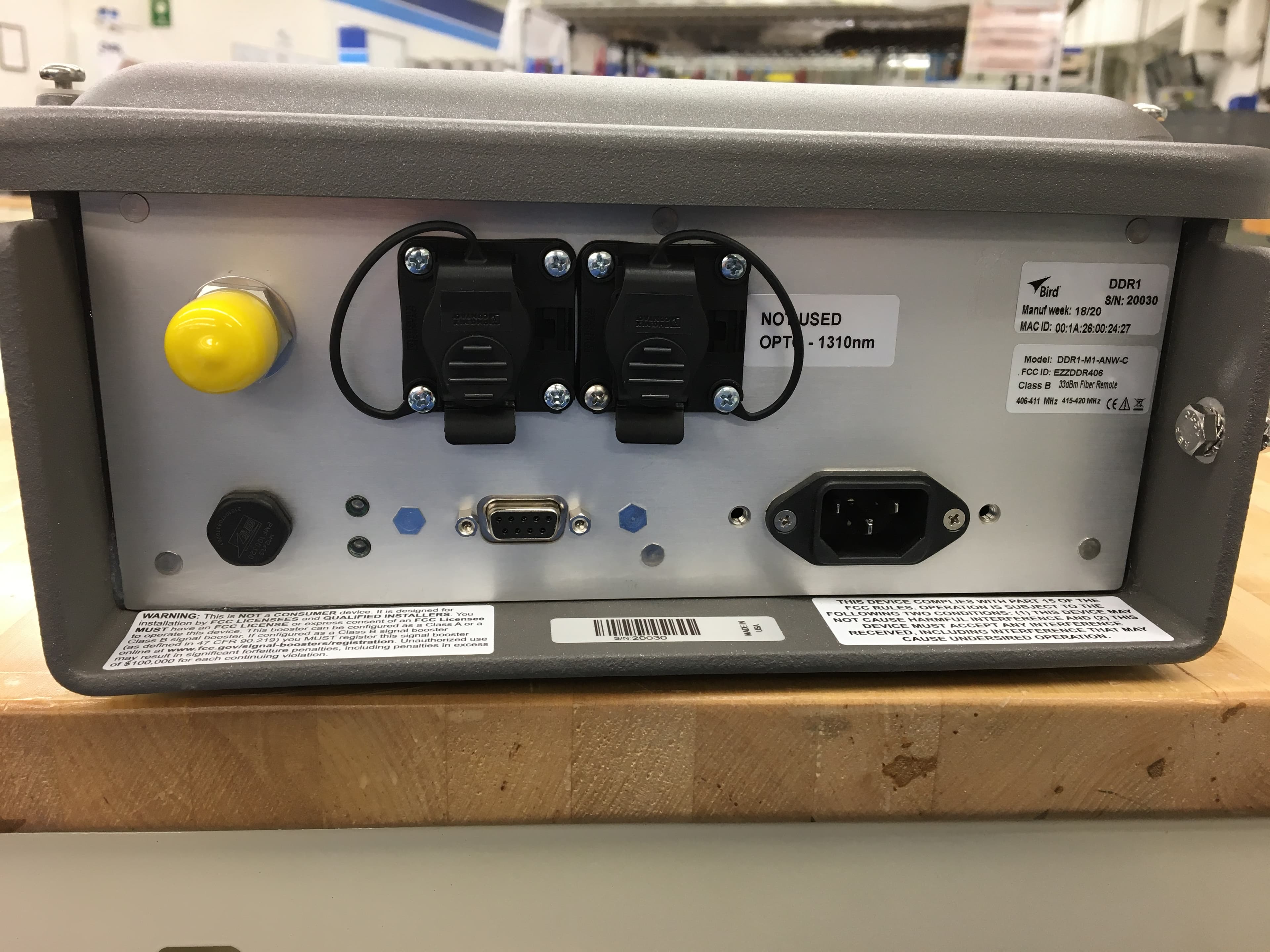
EZZDDR406
Jun 24, 2020DDR Low Band UHF Remote
Equipment Class
B9B - Part 90 Class B Industrial Booster (non-SMR)
EZZ61470
May 19, 2015UHF Digital Signal Booster
Equipment Class
B9A - Part 90 Class A Industrial Booster (non-SMR)
EZZ61470A
May 18, 2015UHF Digital Signal Booster
Equipment Class
B9A - Part 90 Class A Industrial Booster (non-SMR)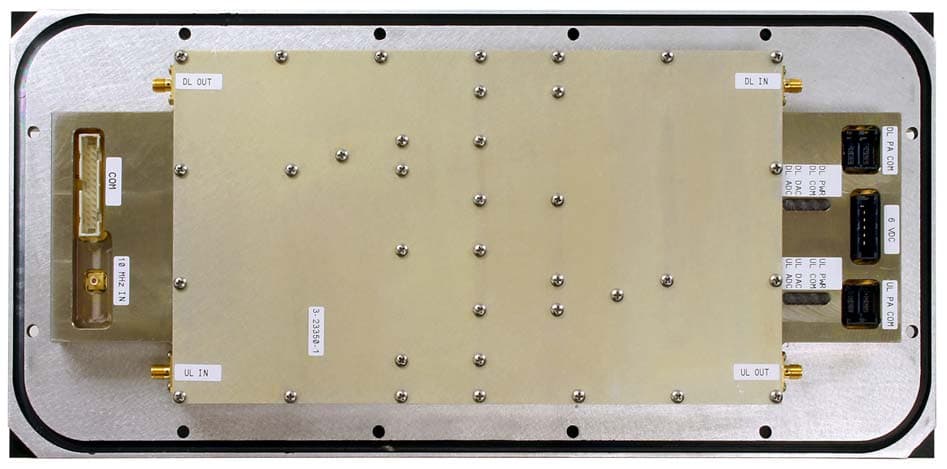
EZZ6138
Sep 21, 2011Channelized Signal Booster
Equipment Class
TNB - Licensed Non-Broadcast Station Transmitter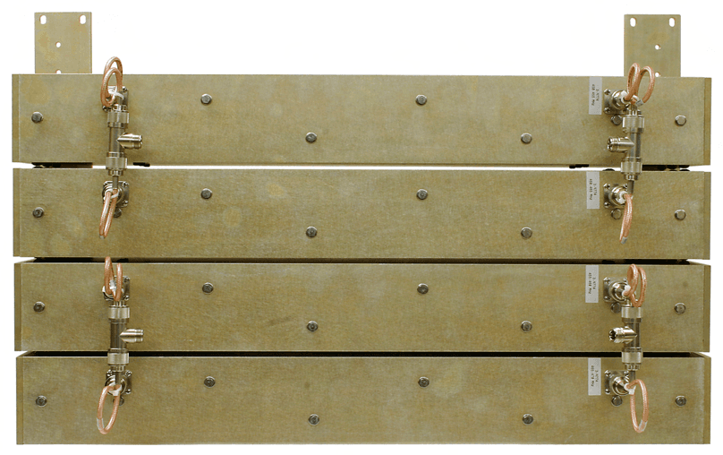
EZZ61170A
Mar 01, 2010Channelized Signal Booster
Equipment Class
TNB - Licensed Non-Broadcast Station Transmitter