EZZ5PI618350SIGNAL BOOSTER II
Bird Technologies Group
Click to zoom
Application Details
- Equipment Class
- TNB - Licensed Non-Broadcast Station Transmitter
- Date of Grant
- Oct 26, 2005
- Application Purpose
- Original Equipment
- Date of Application
- Oct 26, 2005
- Equipment Note
- SIGNAL BOOSTER II
- Frequency Range
- 794.00000000 - 806.00000000
- Company
- Bird Technologies Group
- Country
- United States
Documents & Files
Document Text
Text extracted from the exhibit documents filed with the FCC. Open a document above to read the original.
Users Manual
Part No. 61-83B-50-XXX-XX UserMan page 1 of 25 Installation and Operation Manual for the Two-Way Signal Booster System Model Number 61-83B-50-XXX-XX First Printing: July 2005 7-9410-1.2 Version NumberVersion Date 107/20/05 1.109/19/05 1.210/21/05 Copyright © 2005 TX RX Systems Inc. 61-83B-50-XXX-XX UserMan page 2 of 25 NOTE WARNING Warranty This warranty applies for one year from shipping date. TX RX Systems Inc. warrants its products to be free from defect in material and workman- ship at the time of shipment. Our obligation under warranty is limited to replacement or repair, at our option, of any such products that shall have been defective at the time of manufacture. TX RX Systems Inc. reserves the right to replace with merchandise of equal performance although not identical in every way to that originally sold. TX RX Systems Inc. is not liable for damage caused by lightning or other natural disasters. No product will be accepted for repair or replacement without our prior written approval. The purchaser must prepay all shipping charges on returned products. TX RX Systems Inc. shall in no event be liable for consequential damages, installation costs or expense of any nature resulting from the purchase or use of products, whether or not they are used in accordance with instructions. This warranty is in lieu of all other warranties, either ex- pressed or implied, including any implied warranty or merchantability of fitness. No repre- sentative is authorized to assume for TX RX Systems Inc. any other liability or warranty than set forth above in connection with our products or services. Terms and Conditions of Sale PRICES AND TERMS: Prices are FOB seller’s plant in Angola, NY domestic packaging only, and are subject to change without notice. Federal, State and local sales or excise taxes are not included in prices. When Net 30 terms are applicable, payment is due within 30 days of invoice date. All orders are subject to a $100.00 net minimum. QUOTATIONS: Only written quotations are valid. ACCEPTANCE OF ORDERS: Acceptance of orders is valid only when so acknowledged in writing by the seller. SHIPPING: Unless otherwise agreed at the time the order is placed, seller reserves the right to make partial shipments for which payment shall be made in accordance with seller’s stated terms. Shipments are made with transportation charges collect unless otherwise specified by the buyer. Seller’s best judgement will be used in routing, except that buyer’s routing is used where practicable. The seller is not responsible for selection of most economical or timeliest routing. CLAIMS: All claims for damage or loss in transit must be made promptly by the buyer against the carrier. All claims for shortages must be made within 30 days after date of shipment of material from the seller’s plant. SPECIFICATION CHANGES OR MODIFICATIONS: All designs and specifications of seller’s products are subject to change without notice provided the changes or modifi- cations do not affect performance. RETURN MATERIAL: Product or material may be returned for credit only after written authorization from the seller, as to which seller shall have sole discretion. In the event of such authorization, credit given shall not exceed 80 percent of the original purchase. In no case will Seller authorize return of material more than 90 days after shipment from Seller’s plant. Credit for returned material is issued by the Seller only to the original purchaser. ORDER CANCELLATION OR ALTERATION: Cancellation or alteration of acknowledged orders by the buyer will be accepted only on terms that protect the seller against loss. NON WARRANTY REPAIRS AND RETURN WORK: Consult seller’s plant for pricing. Buyer must prepay all transportation charges to seller’s plant. Standard shipping policy set forth above shall apply with respect to return shipment from TX RX Systems Inc. to buyer. Disclaimer Product part numbering in photographs and drawings is accurate at time of printing. Part number labels on TX RX products supercede part numbers given within this manual. Information is subject to change without notice. Symbols Commonly Used CAUTION or ATTENTION High Voltage Use Safety Glasses ESD Electrostatic Discharge Hot Surface Electrical Shock Hazard Important Information 61-83B-50-XXX-XX UserMan page 3 of 25 To satisfy FCC RF exposure requirements for transmitting devices, a separation distance of 104 Centimeters or more should be maintained between the UPLINK antenna of this device and persons during device operation. To satisfy FCC RF exposure requirements for transmitting devices, a sepa- ration distance of 33 Centimeters or more should be main- tained between the DOWNLINK antenna of this device and persons during device operation. To ensure compliance, operations at closer than these distances is not recom- mended. The antenna used for this transmitter must not be co-located in conjunction with any other antenna or transmitter. WARNING For Class A Unintentional Radiators This equipment has been tested and found to comply with the limits for a Class A digital device, pursuant to part 15 of the FCC rules. These limits are designed to provide reasonable protection against harmful inter- ference when the equipment is operated in a commercial environment. This equipment generates, uses, and can radiate radio frequency energy and, if not installed and used in accordance with the instruction manual, may cause harmful interference to radio communications. Operation of this equipment in a resi- dential area is likely to cause harmful interference in which case the user will be required to correct the interference at his own expense. Changes or modifications not expressly approved by TX RX System Inc. could void the user’s authority to operate the equipment. WARNING This device complies with Part 15 of the FCC Rules. Operation is subject to the following two conditions: (1) this device may not cause harmful interference and (2) this device must accept any…
Text truncated - open the document above for the full version.
Cover Letter(s)
TX RX Systems, Inc. 8625 Industrial Parkway, Angola, NY 14006 Phone (716) 549 4700 Fax (716) 549-4772 August 5, 2005 FEDERAL COMMUNICATIONS COMMISSION 7435 Oakland Mills Road Columbia, MD 21046 U.S.A. Subject: Request for withholding from public disclosure the schematic diagrams and system block dia- grams pursuant to an application for certification. Applicant:TX RX Systems, inc. Product: Signal Booster II Model: 61-83B-50 FCC ID: EZZ5PI618350 Dear Sir/Madam, We, TX RX Systems, Inc.,would like to request that the schematic diagrams, system block dia- grams, parts list and Operational description submitted with the application for certification be withheld from public disclosure as per Section 0.459 of FCC Rules. This request is made under the provisions of Section 0.457(d) of the Commission's Rules, and Section 552(b)(4) of the Free- dom of Information Act. These sections authorize a withholding from public inspection materials which would be privileged as a matter of law if retained by the person submitting them, and mate- rials which would not customarily be released to the public by that person. If you have any queries, please do not hesitate to contact us. OUR TELEPHONE NO.:(716) 549 4700 ext. 5080 Yours truly, Dennis G. Hohman, Manager Engineering Services
External Photos
61-83B-50-XXX-XX-LabelLoc page 2 of 2 TX RX SYSTEMS, INC. SERIAL # GR938 61-83B-50-A12-G1 TX RX SYSTEMS, INC. IC: 1940A-PI618350 TX RX SYSTEMS, INC. SERIAL # GR938 SERIAL # GR938 61-83B-50-A12-G161-83B-50-A12-G1 TX RX SYSTEMS, INC. IC: 1940A-PI618350 IC: 1940A-PI618350 11" 2.25" 61-83B-50-XXX-XX ExtPhot page 2 of 14 Cabinet Rear View 61-83B-50-XXX-XX ExtPhot page 3 of 14 Cabinet Right Side View Cabinet Left Side View Cabinet Bottom View Cabinet Top View
ID Label/Location Info
61-83B-50-XXX-XX-LabelSmpl page 1 of 1 TX RX SYSTEMS, INC. FCC ID: EZZ5PI618350 TX RX SYSTEMS, INC. IC: 1940A-PI618350 Sample of FCC Label Sample of IC Label 61-83B-50-XXX-XX-LabelLoc page 1 of 2 TX RX SYSTEMS, INC. SERIAL # GR938 61-83B-50-A12-G1 TX RX SYSTEMS, INC. FCC ID: EZZ5PI618350 TX RX SYSTEMS, INC. SERIAL # GR938 SERIAL # GR938 61-83B-50-A12-G161-83B-50-A12-G1 TX RX SYSTEMS, INC. FCC ID: EZZ5PI618350 FCC ID: EZZ5PI618350 11" 2.25" 61-83B-50-XXX-XX-LabelLoc page 2 of 2 TX RX SYSTEMS, INC. SERIAL # GR938 61-83B-50-A12-G1 TX RX SYSTEMS, INC. IC: 1940A-PI618350 TX RX SYSTEMS, INC. SERIAL # GR938 SERIAL # GR938 61-83B-50-A12-G161-83B-50-A12-G1 TX RX SYSTEMS, INC. IC: 1940A-PI618350 IC: 1940A-PI618350 11" 2.25"
Internal Photos
61-83B-50-XXX-XX ExtPhot page 1 of 15 61-83B-50-A12-G1 Two-Way Signal Booster System Cabinet Inside View 61-83B-50-XXX-XX ExtPhot page 4 of 15 8-20667 Power Supply Assembly 61-83B-50-XXX-XX ExtPhot page 5 of 15 3-21111 Filter Assembly 61-83B-50-XXX-XX ExtPhot page 6 of 15 3-21121 Downlink Power Amplifier Assembly 3-21119 Uplink Power Amplifier Assembly 61-83B-50-XXX-XX ExtPhot page 7 of 15 3-19576 Mid-Level Amplifier Assembly 61-83B-50-XXX-XX ExtPhot page 8 of 15 3-19575 Low-Level Amplifier Assembly 61-83B-50-XXX-XX ExtPhot page 9 of 15 3-19833 Power Distribution Card 61-83B-50-XXX-XX ExtPhot page 10 of 15 3-19832 Controller Card 61-83B-50-XXX-XX ExtPhot page 11 of 15 3-20294 Low Gain Amplifier Assembly 61-83B-50-XXX-XX ExtPhot page 12 of 15 3-20208 Attenuator Card Assembly 61-83B-50-XXX-XX ExtPhot page 13 of 15 3-3060 Signal Sampler Assembly 61-83B-50-XXX-XX ExtPhot page 14 of 15 8-20748 Isolator Assembly 61-83B-50-XXX-XX ExtPhot page 15 of 15 3-21226 DC Filter Assembly 61-83B-50-XXX-XX IntPhot page 1 of 9 3-21119 and 3-21121 Power Amplifier Assembly Front PCB View 3-21119 and 3-21121 Power Amplifier Assembly Back PCB View 61-83B-50-XXX-XX IntPhot page 2 of 9 3-19576 Mid-Level Amplifier Assembly Front PCB View 3-19576 Mid-Level Amplifier Assembly Back PCB View 61-83B-50-XXX-XX IntPhot page 3 of 9 3-19575 Low-Level Amplifier Assembly Front PCB View 3-19575 Low-Level Amplifier Assembly Back PCB View 61-83B-50-XXX-XX IntPhot page 4 of 9 3-19833 Power Distribution Card Front PCB View 3-19833 Power Distribution Card Back PCB View 61-83B-50-XXX-XX IntPhot page 5 of 9 3-19832 Controller Card Front PCB View 3-19832 Controller Card Back PCB View 61-83B-50-XXX-XX IntPhot page 6 of 9 3-20294 Low Gain Amplifier Front PCB View 3-20294 Low Gain Amplifier Back PCB View 61-83B-50-XXX-XX IntPhot page 7 of 9 3-20208 Attenuator Card Front PCB View 3-20208 Attenuator Card Back PCB View 61-83B-50-XXX-XX IntPhot page 8 of 9 3-19826 Card Cage Front PCB View 3-19826 Card Cage Back PCB View 61-83B-50-XXX-XX IntPhot page 9 of 9 3-21226 DC Filter Front PCB View 3-21226 DC Filter Rear PCB View
Parts List/Tune Up Info
Manual 7-9410-1.1 Page 22 TX RX Systems Inc. 09/19/05 61-83B-50-XXX-XX UserMan page 22 of 25 2) Gently tilt only the top of the assembly up from the card cage. Keep the bottom of the assembly in place. The bottom mounting plate (part of the card cage) has an overhang on it to support the display/user interface board. If the assembly is lifted straight out the overhang it could possibly damage the interface circuit board. 3) With the display/user interface board standing up straight gently move it upwards while lifting it out about an inch or two. This should allow the overhang to clear the interface circuit board without damage. 4) Remove the ribbon cable that connects the dis- play/user interface assembly to the card cage, see Figure 13. 5) To replace the display/user interface assembly repeat steps 1 through 4 in reverse order. Power Supply Replacement The SB II power supply assembly is field replace- able. Follow the steps listed below in sequential order. The required tools are a #1 Phillips screw- driver. 1) Turn off AC power at the junction box. 2) Disconnect the 3 conductor cable that brings AC power to the supply from the junction box. 3) Disconnect the red and black leads from the power supply that connect to the card cage. 4) Remove the Phillips screws that hold the power supply mount bracket to the back plate and remove the assembly from the cabinet. 5) Reverse steps 4 through 2 to install the replace- ment power supply. Duplexer / Filter Replacement The filter assemblies are field replaceable. Follow the steps listed below in sequential order. The required tools are a #1 Phillips screwdriver with an extended shaft to reach down far enough into the unit to loosen the mounting screws. Note: Power to the SB II cabinet must be turned OFF during the filter replacement process. 1) All RF cables attached to the assembly must be removed (5/16î wrench). 2) Remove the Phillips screws that hold the assembly mount brackets to the back plate and remove the assembly from the cabinet. 3) Reverse steps 2 and 1 to install the replace- ment filter. When replacing the RF cables do not overtighten the SMA connectors. They should be tightened just slightly more than hand tight or to the specification of 7 in/lbs. Card Cage Replacement To replace the card cage follow the steps listed below in sequential order. The required tools are a #1 Phillips screwdriver with an extended shaft to reach down far enough into the unit to loosen the mounting screws. Note: Power to the SB II cabinet must be turned OFF during the card cage replacement process. 1) Disconnect the display/user interface assembly. 2) Disconnect 4 cables at the backplane of the card cage which are assessable with the dis- play/user interface board out of the way. 3) Remove the row of Phillips screws which hold the card cage to the back plate. There is a row of screws at the top and bottom of the cage. 4) To install a replacement cage perform steps 3 through 1 in reverse order. Tuning Instructions Tuning instructions are provided in support of field service activities. It is assumed that the procedures listed in this manual will be carried out by a quali- fied electronics technician observing all standard safety practices. The amplifier assemblies used in the model 61- 83B-50-XXX-XX signal boosters are of sufficient bandwidth to cover the entire range of operation. Tuning is not required. The individual filters used in the duplexer are passive devices of rugged electri- cal and mechanical design. They are tuned at the factory for the original design requirements and require no adjustment or maintenance. These devices will stay properly tuned unless they have NOTE NOTE Manual 7-9410-1.1 Page 23 TX RX Systems Inc. 09/19/05 61-83B-50-XXX-XX UserMan page 23 of 25 been physically damaged or are tampered with. Combline preselector filters provide the input and output selectivity for the system. These filters have a carefully shaped response curve that passes a number of contiguous communication channels with each filter designed to cover a 12 MHz band- width. TEST EQUIPMENT A two channel network analyzer that simulta- neously displays both transmission and reflection is best for properly tuning a preselector. A single channel tracking generator/spectrum analyzer combination may be adequate but is not accurate enough to verify factory specifications. A return loss bridge would also be required when using a tracking generator. Skill and experience are also needed and the personnel doing the work should be thoroughly familiar with the use of the network analyzer. A Hewlett Packard 8752B or equivalent network analyzer is recommended. PRESELECTOR TUNING The following is a general outline of the tuning pro- cedure. 1) Connect test equipment as shown in Figure 14. 2) Set the analyzer to the desired center fre- quency and desired bandwidth. 3) Loosen the tuning rod locking nuts. 4) If the preselector is severely out of tune, set the analyzer for 10 dB/div vertical scale on the transmission channel and alternately adjust the tuning rods in pairs working from the center to the end rods for maximum signal at the center frequency. Note that for preselectors with an odd number of rods, start with the center rod and then move to the pairs, one on either side of center. 5) Repeat step 4 tuning to maximize the signal at the center frequency. The response should start to take on the desired shape and symmetry. Setup the analyzer for 1 dB/div (2 dB/div for a tracking generator) on the transmission channel and then re-adjust the rods in the same fashion. Make sure that the return loss curve meets or exceeds the published specification over the range and is relatively symmetrical. Fine adjust the tuning rods to adjust symmetry. 7) Lock all tuning rods after the desired response is obtained. Note that a slight dissymmetry in either the transmission or reflection response may be unavoidable. RECOMMENDED SPARES It is recommended that one spare of each of the followin…
Text truncated - open the document above for the full version.
Test Report
Signal Booster II Model No.: 61-83B-50 FCC ID: EZZ5PI618350 Applicant: TX RX Systems, Inc. 8625 Industrial Parkway Angola, NY 14006 USA Tested in Accordance With Federal Communications Commission (FCC) 47 CFR, Parts 2 and 90 (Subpart R) UltraTech's File No.: TXRX-013F90R This Test report is Issued under the Authority of Tri M. Luu, Professional Engineer, Vice President of Engineering UltraTech Group of Labs Date: October 5, 2005 Report Prepared by: Dan Huynh Issued Date: October 5, 2005 Tested by: Hung Trinh and Wayne Wu Test Dates: August 9 - 22, 2005 The results in this Test Report apply only to the sample(s) tested, and the sample tested is randomly selected. This report must not be used by the client to claim product endorsement by NVLAP or any agency of the US Government. UltraTech 3000 Bristol Circle, Oakville, Ontario, Canada, L6H 6G4 Tel.: (905) 829-1570 Fax: (905) 829-8050 Website: www.ultratech-labs.com , Email: [email protected], Email: [email protected] 2 31040/SIT C-1376 46390-2049 200093-0 SL2-IN-E-1119R 00-034 FCC Parts 2 and 90 (Subpart R) Contents i Signal Booster II, Model 61-83B-50 FCC ID: EZZ5PI618350 ULTRATECH GROUP OF LABS File #: TXRX-013F90R 3000 Bristol Circle, Oakville, Ontario, Canada L6H 6G4 October 5, 2005 Tel. #: 905-829-1570, Fax. #: 905-829-8050, Email: [email protected] , Website: http://www.ultratech-labs.com All test results contained in this engineering test report are traceable to National Institute of Standards and Technology (NIST) TABLE OF CONTENTS EXHIBIT 1. SUBMITTAL CHECK LIST ..........................................................................................................................................1 EXHIBIT 2. INTRODUCTION ............................................................................................................................................................2 2.1. SCOPE ............................................................................................................................................................................................2 2.2. RELATED SUBMITTAL(S)/GRANT(S).......................................................................................................................................2 2.3. NORMATIVE REFERENCES .......................................................................................................................................................2 EXHIBIT 3. PERFORMANCE ASSESSMENT .................................................................................................................................3 3.1. CLIENT INFORMATION ..............................................................................................................................................................3 3.2. EQUIPMENT UNDER TEST (EUT) INFORMATION.................................................................................................................3 3.3. EUT’S TECHNICAL SPECIFICATIONS......................................................................................................................................4 3.4. LIST OF EUT’S PORTS.................................................................................................................................................................5 3.5. ANCILLARY EQUIPMENT ..........................................................................................................................................................5 3.6. GENERAL TEST SETUP...............................................................................................................................................................5 EXHIBIT 4. EUT OPERATING CONDITIONS AND CONFIGURATIONS DURING TESTS...................................................6 4.1. CLIMATE TEST CONDITIONS ...................................................................................................................................................6 4.2. OPERATIONAL TEST CONDITIONS & ARRANGEMENT FOR TEST SIGNALS.................................................................6 EXHIBIT 5. SUMMARY OF TEST RESULTS..................................................................................................................................7 5.1. LOCATION OF TESTS..................................................................................................................................................................7 5.2. APPLICABILITY & SUMMARY OF EMC EMISSION TEST RESULTS ..................................................................................7 5.3. MODIFICATIONS INCORPORATED IN THE EUT FOR COMPLIANCE PURPOSES............................................................8 EXHIBIT 6. MEASUREMENTS, EXAMINATIONS & TEST DATA FOR EMC EMISSIONS ..................................................9 6.1. TEST PROCEDURES ....................................................................................................................................................................9 6.2. MEASUREMENT UNCERTAINTIES ..........................................................................................................................................9 6.3. MEASUREMENT EQUIPMENT USED .......................................................................................................................................9 6.4. ESSENTIAL/PRIMARY FUNCTIONS AS DECLARED BY THE MANUFACTURER ............................................................9 6.5. RF POWER OUTPUT & INTERMODULATION [§§ 2.1046 & 90.541].................................................................... ................ 10 6.6. RF EXPOSURE REQUIREMENTS [§§ 1.1310 & 2.1091].......................................................................................................... 31 6.7. OCCUPIED BANDWIDTH [§ 2.1049] ........................................................................................................................................ 35 6.8. SPURIOUS EMISSIONS AT…
Text truncated - open the document above for the full version.
Contact Information
Applicant
Amy Sanvido(RF Engineer)
Test Firm
UltraTech Engineering Labs Inc.Tri Luu
Technical Specifications
| # | Rule Parts | Frequency Range | Power Output | Emission | Tolerance |
|---|---|---|---|---|---|
| 6 | 9 | 794 MHz - 806 MHz | 4 W | G3E | Amp |
Other Applications from Bird Technologies Group
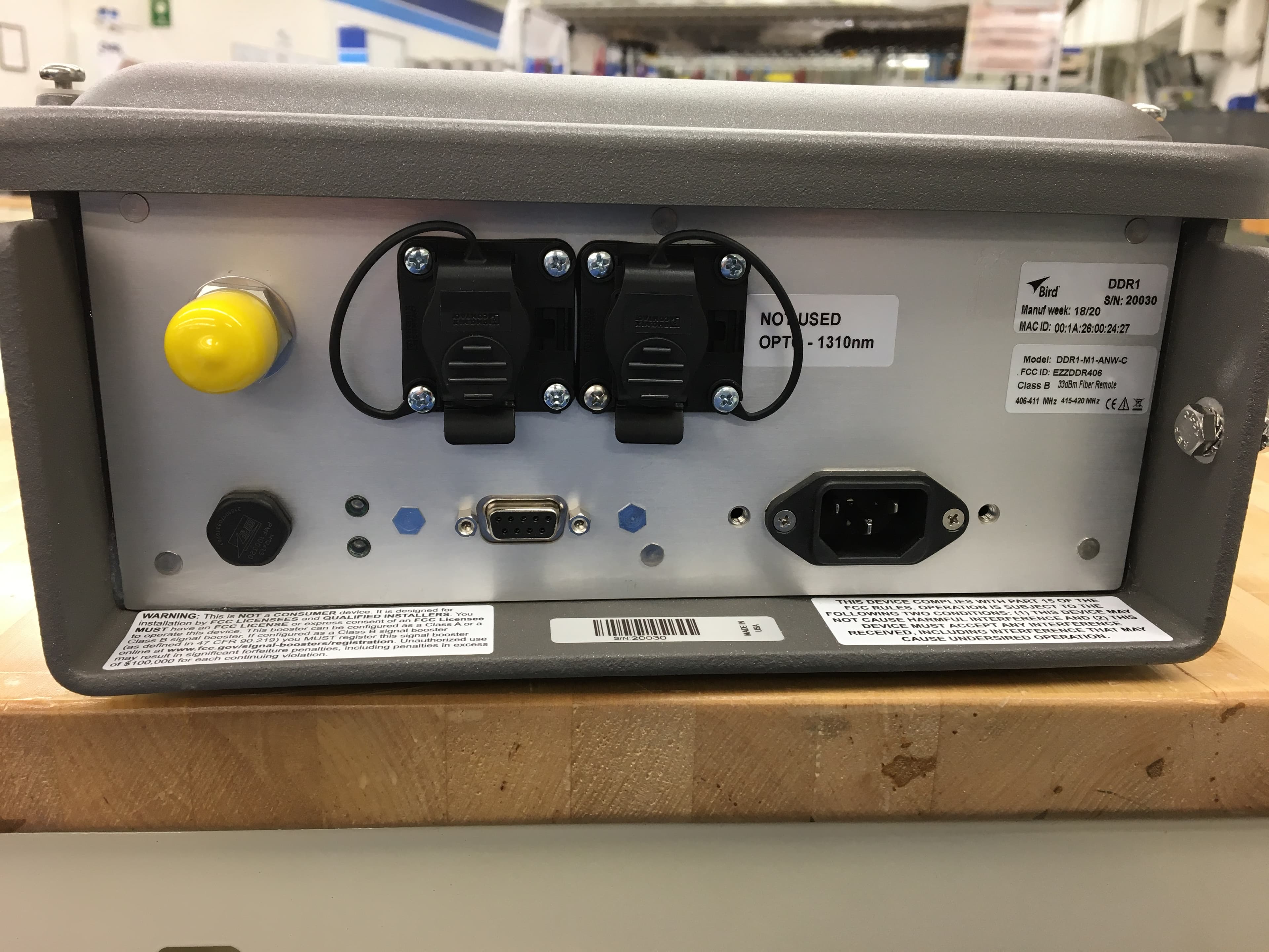
EZZDDR406
Jun 24, 2020DDR Low Band UHF Remote
Equipment Class
B9B - Part 90 Class B Industrial Booster (non-SMR)
EZZ61470
May 19, 2015UHF Digital Signal Booster
Equipment Class
B9A - Part 90 Class A Industrial Booster (non-SMR)
EZZ61470A
May 18, 2015UHF Digital Signal Booster
Equipment Class
B9A - Part 90 Class A Industrial Booster (non-SMR)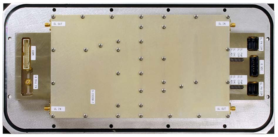
EZZ6138
Sep 21, 2011Channelized Signal Booster
Equipment Class
TNB - Licensed Non-Broadcast Station Transmitter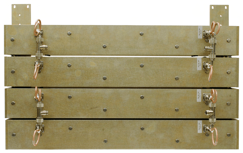
EZZ61170A
Mar 01, 2010Channelized Signal Booster
Equipment Class
TNB - Licensed Non-Broadcast Station Transmitter