EZZ5PI618850BI-DIRECTIONAL SIGNAL BOOSTER
Bird Technologies Group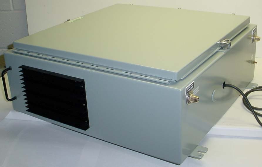
Click to zoom
Application Details
- Equipment Class
- TNB - Licensed Non-Broadcast Station Transmitter
- Date of Grant
- Nov 01, 2004
- Application Purpose
- Original Equipment
- Date of Application
- Nov 01, 2004
- Equipment Note
- BI-DIRECTIONAL SIGNAL BOOSTER
- Frequency Range
- 935.00000000 - 940.00000000
- Company
- Bird Technologies Group
- Country
- United States
Documents & Files
Document Text
Text extracted from the exhibit documents filed with the FCC. Open a document above to read the original.
Users Manual
Part No . Installation and Operation Manual for the Two-Way Signal Booster System Model Number 61-88-50 First Printing: May 2004 7-9375-4 Ve r si o n N u m b e rVe r s i o n D a t e 105/06/04 210/06/04 310/2704 410/29/04 Copyright © 2004 TX RX Systems Inc. 61-88-50 UserMan Page 1 of 29 NOTE WARNING Warranty This warranty applies for one year from shipping date. TX RX Systems Inc. warrants its products to be free from defect in material and workman- ship at the time of shipment. Our obligation under warranty is limited to replacement or repair, at our option, of any such products that shall have been defective at the time of manufacture. TX RX Systems Inc. reserves the right to replace with merchandise of equal performance although not identical in every way to that originally sold. TX RX Systems Inc. is not liable for damage caused by lightning or other natural disasters. No product will be accepted for repair or replacement without our prior written approval. The purchaser must prepay all shipping charges on returned products. TX RX Systems Inc. shall in no event be liable for consequential damages, installation costs or expense of any nature resulting from the purchase or use of products, whether or not they are used in accordance with instructions. This warranty is in lieu of all other warranties, either ex- pressed or implied, including any implied warranty or merchantability of fitness. No repre- sentative is authorized to assume for TX RX Systems Inc. any other liability or warranty than set forth above in connection with our products or services. Terms and Conditions of Sale PRICES AND TERMS: Prices are FOB seller’s plant in Angola, NY domestic packaging only, and are subject to change without notice. Federal, State and local sales or excise taxes are not included in prices. When Net 30 terms are applicable, payment is due within 30 days of invoice date. All orders are subject to a $100.00 net minimum. QUOTATIONS: Only written quotations are valid. ACCEPTANCE OF ORDERS: Acceptance of orders is valid only when so acknowledged in writing by the seller. SHIPPING: Unless otherwise agreed at the time the order is placed, seller reserves the right to make partial shipments for which payment shall be made in accordance with seller’s stated terms. Shipments are made with transportation charges collect unless otherwise specified by the buyer. Seller’s best judgement will be used in routing, except that buyer’s routing is used where practicable. The seller is not responsible for selection of most economical or timeliest routing. CLAIMS: All claims for damage or loss in transit must be made promptly by the buyer against the carrier. All claims for shortages must be made within 30 days after date of shipment of material from the seller’s plant. SPECIFICATION CHANGES OR MODIFICATIONS: All designs and specifications of seller’s products are subject to change without notice provided the changes or modifi- cations do not affect performance. RETURN MATERIAL: Product or material may be returned for credit only after written authorization from the seller, as to which seller shall have sole discretion. In the event of such authorization, credit given shall not exceed 80 percent of the original purchase. In no case will Seller authorize return of material more than 90 days after shipment from Seller’s plant. Credit for returned material is issued by the Seller only to the original purchaser. ORDER CANCELLATION OR ALTERATION: Cancellation or alteration of acknowledged orders by the buyer will be accepted only on terms that protect the seller against loss. NON WARRANTY REPAIRS AND RETURN WORK: Consult seller’s plant for pricing. Buyer must prepay all transportation charges to seller’s plant. Standard shipping policy set forth above shall apply with respect to return shipment from TX RX Systems Inc. to buyer. Disclaimer Product part numbering in photographs and drawings is accurate at time of printing. Part number labels on TX RX products supercede part numbers given within this manual. Information is subject to change without notice. Symbols Commonly Used CAUTION or ATTENTION High Voltage Use Safety Glasses ESD Electrostatic Discharge Hot Surface Electrical Shock Hazard Important Information 61-88-50-UserMan Page 2 of 29 To satisfy FCC RF exposure requirements for transmitting devices, a separation distance of 1.0 Meters or more should be maintained between the UPLINK antenna of this device and persons during device operation. To satisfy FCC RF exposure requirements for mobile transmitting devices, a separation distance of 0.3 Meters or more should be main- tained between the DOWNLINK antenna of this device and persons during device operation. To ensure compliance, operations at closer than these distances is not recom- mended. The antenna used for this transmitter must not be co-located in conjunction with any other antenna or transmitter. WARNING NOTE: This equipment has been tested and found to comply with the limits for a Class B digital device, pur- suant to part 15 of the FCC Rules. These limits are designed to provide reasonable protection against harmful interference in a residential installation. This equipment generates, uses and can radiate radio fre- quency energy and, if not installed and used in accordance with the instructions, may cause harmful inter- ference to radio communications. However, there is no guarantee that interference will not occur in a particular installation. If this equipment does cause harmful interference to radio or television reception, which can be determined by turning the equipment off and on, the user is encouraged to try to correct the interference by one or more of the following measures: — Reorient or relocate the receiving antenna. — Increase the separation between the equip- ment and receiver. — Connect the equipment into an outlet on a circuit different from that to which the re- ceiver is connected. — Consult the dealer or an experienced radio! TV technic…
Text truncated - open the document above for the full version.
Users Manual
Manual 7-9375-4 Page 10TX RX Systems Inc. 10/29/04 display which does require a button press to exit. The main status display shows the uplink and downlink gain in dB as well as the uplink and down- link output level in dBm. The last line of the main status display gives a summary status message for the entire signal booster. In this example “Status OK” is being dis- played. Pressing the “ENTER” button will move you from the main status display into the menu selec- tions and will permit interaction with the system. There are two main functions available within the software menus including configuration settings and detailed status displays. Configuration Settings In most cases, the factory default settings are the optimum values for adjustable parameters. The most common setting to be changed by the sys- tem’s technician is the gain setting. This is normally done to compensate for varying values of antenna isolation as outlined earlier in this manual or to reduce excessive OLC action resulting from exces- sive gain. Please thoroughly study this section before making any adjustments to the configuration values. Each configured item is discussed in detail. RESTORE ORIG CONFIG This command will restore all configured settings to their original factory default values. SB II ships from the factory preset to the lowest gain possible. CALIBRATE CURRENTS Use this command when replacing an RF amplifier. This function automatically calibrates the current alarm “trip” point of each amplifier in the system. Due to manufacturing tolerances there are small differences in current draw between amplifier assemblies. This software function matches the alarm sensing circuit to the respective amplifier assembly and should be repeated whenever an amplifier assembly is replaced. SET GAIN This function allows the user to electronically set the gain of the booster in 0.5 dB increments over a range of 30 dB. Gain can be adjusted indepen- dently for both the uplink and downlink channels but in most cases both uplink and downlink should be set to the same gain value. Know your antenna isolation before making this adjustment. We recommend that you temporarily disconnect both the uplink and downlink antennas when setting the gain to avoid the possibility of causing the unit to oscillate. After changing the set- ting, power the unit down, reconnect the antennas and power-up the booster. Note: A reduction in system gain will also result in an equal reduction in the OLC dynamic range, refer to the sec- tion titled “OLC” on page 11. SET OUTPUT LEVEL Allows the output power for the uplink and downlink channels to be independently adjusted in.5 dB increments up to +31 dBm. Note that the OLC cir- cuitry will maintain the systems output level at the values you have selected in this menu. Use this function ONLY if your system is causing some form of interference to another radio system. You can only reduce the booster’s output power with this command. CHANGE GAIN CONFIGURATION Insures proper gain readings when changing basic booster gain by changing the type of plug-in card assemblies. Use of this menu is ONLY needed when converting your stock SB II to a different gain level by chang- ing the low level, mid-level plug-in amplifier card or the addition of an attenuator card. It actually is a change to the characteristics of another model. Don’t confuse this with simple amplifier bypassing to reduce gain. Uplink and down link can be set independently. Choices for gain are Full, Mid or Low and the Enter key toggles the gain setting. The corresponding gain level is displayed. Select Done using the arrow keys and press enter to return to the menu. Use the Cancel button to return to the Status Display. Detailed Status Screens These items allow a detailed examination of sys- tem components including; all amplifiers (current draw and temperature), the power supply (voltage level), and the OLC function (present status and historical archive). Each item is discussed below in detail. NOTE 61-88-50-UserMan Page 16 of 29 Manual 7-9375-4 Page 11TX RX Systems Inc. 10/29/04 AMPLIFIERS A separate status screen is available for each amplifier in the system. When an amplifier is selected this function will display the present cur- rent draw of that amp as well as its present operat- ing temperature in degrees Celsius. In addition, a status message will indicate if the amplifier is con- nected and whether the amplifier is bypassed or not bypassed. This menu selection also provides the option of placing an amplifier in bypass or tak- ing an amplifier out of bypass. The current draw will be blank if an amplifier is not connected, will display BYP if the amplifier is bypassed, and will display ATTEN if an attenuator card is being used in place of the amplifier card. The power amplifier currents will nor- mally fluctuate up to 850 ma when sig- nals are present. POWER SUPPLY This function displays the real time power supply voltages for both 24 volt and 12 volt supplies. OLC This screen shows the amount of attenuation pres- ently being used by the OLC for both the uplink and downlink channels. In addition, the percentage of OLC presently being used is also shown. The amount of OLC currently being used in either the uplink or downlink channels is also indicated by LED bar graph displays located on the display panel. Each segment represents 2 to 4 dB of attenuation depending on the gain setting of the booster. The OLC bars should only be active occasionally and no more than 3 or 4 segments briefly lit. Constant light bar activity means the booster gain needs to be reduced for optimum per- formance. The system has 60 dB of OLC dynamic range. However, the dynamic range of the OLC is reduced when the user selectable gain is reduced. The reduction will be an equal amount. For instance, if the user selectable gain is reduced by 20 dB then the OLC dynamic range will also be reduced by 20 dB. OLC DATALOG This screen displays an OLC Datalog which is the OLC d…
Text truncated - open the document above for the full version.
External Photos
ANNEX 2 – EXTERNAL PHOTOGRAPHS TX RX Systems, Inc. Signal Booster 2, Model 61-88-50-A06-G1 FCC ID: EZZ5PI618850 IC: 1940A-PI618850 A2 - 1 ANNEX 2 – EXTERNAL PHOTOGRAPHS TX RX Systems, Inc. Signal Booster 2, Model 61-88-50-A06-G1 FCC ID: EZZ5PI618850 IC: 1940A-PI618850 A2 - 2
ID Label/Location Info
61-88-50-A06-G1 Label Sample Page 1 of 1 TX RX SYSTEMS, INC. FCCID:EZZ5PI618850 TX RX SYSTEMS, INC. IC:1940A-PI618850 Sample of Federal Communications Commission Label Sample of Industry Canada Label 61-88-50-A06-G1-Label Location Page 1 of 2 TX RX SYSTEMS, INC. SERIAL # 3330E SERIAL#3330E 61-88-50-A06-G1 TX RX SYSTEMS, INC. FCC ID: EZZ5PI618850 FCCID:EZZ5PI618850 TX RX SYSTEMS, INC. SERIAL # 3330E SERIAL#3330E 61-88-50-A06-G161-88-50-A06-G1 TX RX SYSTEMS, INC. FCC ID: EZZ5PI618850 FCCID:EZZ5PI618850 11" 2.25" 61-88-50-A06-G1 Label Location Page 2 of 2 TX RX SYSTEMS, INC. SERIAL # 3330E SERIAL#3330E 61-88-50-A06-G1 TX RX SYSTEMS, INC. IC: 1940A-PI618850 IC:1940A-PI618850 TX RX SYSTEMS, INC. SERIAL # 3330E SERIAL#3330E 61-88-50-A06-G161-88-50-A06-G1 TX RX SYSTEMS, INC. IC: 1940A-PI618850 IC:1940A-PI618850 11" 2.25"
Internal Photos
ANNEX 3 – INTERNAL PHOTOGRAPHS TX RX Systems, Inc. Signal Booster 2, Model 61-88-50-A06-G1 FCC ID: EZZ5PI618850 IC: 1940A-PI618850 A2 - 1 ANNEX 3 – INTERNAL PHOTOGRAPHS TX RX Systems, Inc. Signal Booster 2, Model 61-88-50-A06-G1 FCC ID: EZZ5PI618850 IC: 1940A-PI618850 A2 - 2 ANNEX 3 – INTERNAL PHOTOGRAPHS TX RX Systems, Inc. Signal Booster 2, Model 61-88-50-A06-G1 FCC ID: EZZ5PI618850 IC: 1940A-PI618850 A2 - 3 ANNEX 3 – INTERNAL PHOTOGRAPHS TX RX Systems, Inc. Signal Booster 2, Model 61-88-50-A06-G1 FCC ID: EZZ5PI618850 IC: 1940A-PI618850 A2 - 4 ANNEX 3 – INTERNAL PHOTOGRAPHS TX RX Systems, Inc. Signal Booster 2, Model 61-88-50-A06-G1 FCC ID: EZZ5PI618850 IC: 1940A-PI618850 A2 - 5 ANNEX 3 – INTERNAL PHOTOGRAPHS TX RX Systems, Inc. Signal Booster 2, Model 61-88-50-A06-G1 FCC ID: EZZ5PI618850 IC: 1940A-PI618850 A2 - 6 ANNEX 3 – INTERNAL PHOTOGRAPHS TX RX Systems, Inc. Signal Booster 2, Model 61-88-50-A06-G1 FCC ID: EZZ5PI618850 IC: 1940A-PI618850 A2 - 7 ANNEX 3 – INTERNAL PHOTOGRAPHS TX RX Systems, Inc. Signal Booster 2, Model 61-88-50-A06-G1 FCC ID: EZZ5PI618850 IC: 1940A-PI618850 A2 - 8 ANNEX 3 – INTERNAL PHOTOGRAPHS TX RX Systems, Inc. Signal Booster 2, Model 61-88-50-A06-G1 FCC ID: EZZ5PI618850 IC: 1940A-PI618850 A2 - 9 ANNEX 3 – INTERNAL PHOTOGRAPHS TX RX Systems, Inc. Signal Booster 2, Model 61-88-50-A06-G1 FCC ID: EZZ5PI618850 IC: 1940A-PI618850 A2 - 10 ANNEX 3 – INTERNAL PHOTOGRAPHS TX RX Systems, Inc. Signal Booster 2, Model 61-88-50-A06-G1 FCC ID: EZZ5PI618850 IC: 1940A-PI618850 A2 - 11 ANNEX 3 – INTERNAL PHOTOGRAPHS TX RX Systems, Inc. Signal Booster 2, Model 61-88-50-A06-G1 FCC ID: EZZ5PI618850 IC: 1940A-PI618850 A2 - 12 ANNEX 3 – INTERNAL PHOTOGRAPHS TX RX Systems, Inc. Signal Booster 2, Model 61-88-50-A06-G1 FCC ID: EZZ5PI618850 IC: 1940A-PI618850 A2 - 13 ANNEX 3 – INTERNAL PHOTOGRAPHS TX RX Systems, Inc. Signal Booster 2, Model 61-88-50-A06-G1 FCC ID: EZZ5PI618850 IC: 1940A-PI618850 A2 - 14 ANNEX 3 – INTERNAL PHOTOGRAPHS TX RX Systems, Inc. Signal Booster 2, Model 61-88-50-A06-G1 FCC ID: EZZ5PI618850 IC: 1940A-PI618850 A2 - 15 ANNEX 3 – INTERNAL PHOTOGRAPHS TX RX Systems, Inc. Signal Booster 2, Model 61-88-50-A06-G1 FCC ID: EZZ5PI618850 IC: 1940A-PI618850 A2 - 16 ANNEX 3 – INTERNAL PHOTOGRAPHS TX RX Systems, Inc. Signal Booster 2, Model 61-88-50-A06-G1 FCC ID: EZZ5PI618850 IC: 1940A-PI618850 A2 - 17 ANNEX 3 – INTERNAL PHOTOGRAPHS TX RX Systems, Inc. Signal Booster 2, Model 61-88-50-A06-G1 FCC ID: EZZ5PI618850 IC: 1940A-PI618850 A2 - 18 ANNEX 3 – INTERNAL PHOTOGRAPHS TX RX Systems, Inc. Signal Booster 2, Model 61-88-50-A06-G1 FCC ID: EZZ5PI618850 IC: 1940A-PI618850 A2 - 19 ANNEX 3 – INTERNAL PHOTOGRAPHS TX RX Systems, Inc. Signal Booster 2, Model 61-88-50-A06-G1 FCC ID: EZZ5PI618850 IC: 1940A-PI618850 A2 - 20 ANNEX 3 – INTERNAL PHOTOGRAPHS TX RX Systems, Inc. Signal Booster 2, Model 61-88-50-A06-G1 FCC ID: EZZ5PI618850 IC: 1940A-PI618850 A2 - 21 ANNEX 3 – INTERNAL PHOTOGRAPHS TX RX Systems, Inc. Signal Booster 2, Model 61-88-50-A06-G1 FCC ID: EZZ5PI618850 IC: 1940A-PI618850 A2 - 22 ANNEX 3 – INTERNAL PHOTOGRAPHS TX RX Systems, Inc. Signal Booster 2, Model 61-88-50-A06-G1 FCC ID: EZZ5PI618850 IC: 1940A-PI618850 A2 - 23 ANNEX 3 – INTERNAL PHOTOGRAPHS TX RX Systems, Inc. Signal Booster 2, Model 61-88-50-A06-G1 FCC ID: EZZ5PI618850 IC: 1940A-PI618850 A2 - 24 ANNEX 3 – INTERNAL PHOTOGRAPHS TX RX Systems, Inc. Signal Booster 2, Model 61-88-50-A06-G1 FCC ID: EZZ5PI618850 IC: 1940A-PI618850 A2 - 25 ANNEX 3 – INTERNAL PHOTOGRAPHS TX RX Systems, Inc. Signal Booster 2, Model 61-88-50-A06-G1 FCC ID: EZZ5PI618850 IC: 1940A-PI618850 A2 - 26 ANNEX 3 – INTERNAL PHOTOGRAPHS TX RX Systems, Inc. Signal Booster 2, Model 61-88-50-A06-G1 FCC ID: EZZ5PI618850 IC: 1940A-PI618850 A2 - 27 ANNEX 3 – INTERNAL PHOTOGRAPHS TX RX Systems, Inc. Signal Booster 2, Model 61-88-50-A06-G1 FCC ID: EZZ5PI618850 IC: 1940A-PI618850 A2 - 28 ANNEX 3 – INTERNAL PHOTOGRAPHS TX RX Systems, Inc. Signal Booster 2, Model 61-88-50-A06-G1 FCC ID: EZZ5PI618850 IC: 1940A-PI618850 A2 - 29 ANNEX 3 – INTERNAL PHOTOGRAPHS TX RX Systems, Inc. Signal Booster 2, Model 61-88-50-A06-G1 FCC ID: EZZ5PI618850 IC: 1940A-PI618850 A2 - 30 ANNEX 3 – INTERNAL PHOTOGRAPHS TX RX Systems, Inc. Signal Booster 2, Model 61-88-50-A06-G1 FCC ID: EZZ5PI618850 IC: 1940A-PI618850 A2 - 31 ANNEX 3 – INTERNAL PHOTOGRAPHS TX RX Systems, Inc. Signal Booster 2, Model 61-88-50-A06-G1 FCC ID: EZZ5PI618850 IC: 1940A-PI618850 A2 - 32 ANNEX 3 – INTERNAL PHOTOGRAPHS TX RX Systems, Inc. Signal Booster 2, Model 61-88-50-A06-G1 FCC ID: EZZ5PI618850 IC: 1940A-PI618850 A2 - 33 ANNEX 3 – INTERNAL PHOTOGRAPHS TX RX Systems, Inc. Signal Booster 2, Model 61-88-50-A06-G1 FCC ID: EZZ5PI618850 IC: 1940A-PI618850 A2 - 34 ANNEX 3 – INTERNAL PHOTOGRAPHS TX RX Systems, Inc. Signal Booster 2, Model 61-88-50-A06-G1 FCC ID: EZZ5PI618850 IC: 1940A-PI618850 A2 - 35 ANNEX 3 – INTERNAL PHOTOGRAPHS TX RX Systems, Inc. Signal Booster 2, Model 61-88-50-A06-G1 FCC ID: EZZ5PI618850 IC: 1940A-PI618850 A2 - 36 ANNEX 3 – INTERNAL PHOTOGRAPHS TX RX Systems, Inc. Signal Booster 2, Model 61-88-50-A06-G1 FCC ID: EZZ5PI618850 IC: 1940A-PI618850 A2 - 37 ANNEX 3 – INTERNAL PHOTOGRAPHS TX RX Systems, Inc. Signal Booster 2, Model 61-88-50-A06-G1 FCC ID: EZZ5PI618850 IC: 1940A-PI618850 A2 - 38 ANNEX 3 – INTERNAL PHOTOGRAPHS TX RX Systems, Inc. Signal Booster 2, Model 61-88-50-A06-G1 FCC ID: EZZ5PI618850 IC: 1940A-PI618850 A2 - 39 ANNEX 3 – INTERNAL PHOTOGRAPHS TX RX Systems, Inc. Signal Booster 2, Model 61-88-50-A06-G1 FCC ID: EZZ5PI618850 IC: 1940A-PI618850 A2 - 40 ANNEX 3 – INTERNAL PHOTOGRAPHS TX RX Systems, Inc. Signal Booster 2, Model 61-88-50-A06-G1 FCC ID: EZZ5PI618850 IC: 1940A-PI618850 A2 - 41 ANNEX 3 – INTERNAL PHOTOGRAPHS TX RX Systems, Inc. Signal Booster 2, Model 61-88-50-A06-G1 FCC ID: EZZ5PI618850 IC: 1940A-PI618850 A2 - 42 ANNEX 3 – INTERNAL PHOTOGRAPHS TX RX Systems, Inc. Signal Booster 2, Model 61-88-50-A06-G1 FCC ID: EZZ5PI618850 IC: 1940A-PI618850 A2 - 43 ANNEX 3 – INTERNAL PHOTOGRAPHS T…
Text truncated - open the document above for the full version.
Test Report
Signal Booster 2 Model No.: 61-88-50-A06-G1 FCC ID: EZZ5PI618850 Applicant: TX RX Systems, Inc. 8625 Industrial Parkway Angola, NY 14006 USA Tested in Accordance With Federal Communications Commission (FCC) 47 CFR, Parts 2 and 90 (Subpart I) UltraTech's File No.: TXRX-009FCC90 This Test report is Issued under the Authority of Tri M. Luu, Professional Engineer, Vice President of Engineering UltraTech Group of Labs Date: October 14, 2004 Report Prepared by: Anca Dobre Issued Date: October 14, 2004 Tested by: Hung Trinh, EMI/RFI Technician Test Dates: August 16 – September 14, 2004 The results in this Test Report apply only to the sample(s) tested, and the sample tested is randomly selected. This report must not be used by the client to claim product endorsement by NVLAP or any agency of the US Government. UltraTech 3000 Bristol Circle, Oakville, Ontario, Canada, L6H 6G4 Tel.: (905) 829-1570 Fax: (905) 829-8050 Website: www.ultratech-labs.com , Email: [email protected], Email: [email protected] 2 31040/SIT C-1376 46390-2049 200093-0 SL2-IN-E-1119R 00-034 FCC Parts 2 and 90 (Subpart I), Non-Broadcast Radio Transceivers Contents i Signal Booster 2, Model 61-88-50-A06-G1 FCC ID: EZZ5PI618850 ULTRATECH GROUP OF LABS File #: TXRX-009FCC90 3000 Bristol Circle, Oakville, Ontario, Canada L6H 6G4 October 14, 2004 Tel. #: 905-829-1570, Fax. #: 905-829-8050, Email: [email protected] , Website: http://www.ultratech-labs.com All test results contained in this engineering test report are traceable to National Institute of Standards and Technology (NIST) TABLE OF CONTENTS EXHIBIT 1. SUBMITTAL CHECK LIST........................................................................................................................ 1 EXHIBIT 2. INTRODUCTION ......................................................................................................................................... 2 2.1. SCOPE......................................................................................................................................................................... 2 2.2. RELATED SUBMITTAL(S)/GRANT(S)................................................................................................................... 2 2.3. NORMATIVE REFERENCES ................................................................................................................................... 2 EXHIBIT 3. PERFORMANCE ASSESSMENT .............................................................................................................. 3 3.1. CLIENT INFORMATION .......................................................................................................................................... 3 3.2. EQUIPMENT UNDER TEST (EUT) INFORMATION ............................................................................................. 3 3.3. EUT’S TECHNICAL SPECIFICATIONS ..................................................................................................................4 3.4. LIST OF EUT’S PORTS ............................................................................................................................................. 5 3.5. ANCILLARY EQUIPMENT ...................................................................................................................................... 5 3.6. GENERAL TEST SETUP ........................................................................................................................................... 5 EXHIBIT 4. EUT OPERATING CONDITIONS AND CONFIGURATIONS DURING TESTS ............................... 6 4.1. CLIMATE TEST CONDITIONS ................................................................................................................................ 6 4.2. OPERATIONAL TEST CONDITIONS & ARRANGEMENT FOR TEST SIGNALS .............................................. 6 EXHIBIT 5. SUMMARY OF TEST RESULTS ............................................................................................................... 7 5.1. LOCATION OF TESTS .............................................................................................................................................. 7 5.2. APPLICABILITY & SUMMARY OF EMC EMISSION TEST RESULTS ............................................................... 7 5.3. MODIFICATIONS INCORPORATED IN THE EUT FOR COMPLIANCE PURPOSES ........................................ 8 EXHIBIT 6. MEASUREMENTS, EXAMINATIONS & TEST DATA FOR EMC EMISSIONS............................... 9 6.1. TEST PROCEDURES................................................................................................................................................. 9 6.2. MEASUREMENT UNCERTAINTIES ...................................................................................................................... 9 6.3. MEASUREMENT EQUIPMENT USED.................................................................................................................... 9 6.4. ESSENTIAL/PRIMARY FUNCTIONS AS DECLARED BY THE MANUFACTURER ......................................... 9 6.5. RF POWER OUTPUT & INTERMODULATION [§§ 2.1046 & 90.205]................................................................. 10 6.6. RF EXPOSURE REQUIREMENTS [§§ 1.1310 & 2.1091] ...................................................................................... 25 6.7. OCCUPIED BANDWIDTH AND EMISSION MASK [§§ 2.1049, 90.209 & 90.210]............................................. 28 6.8. TRANSMITTER ANTENNA POWER SPURIOUS/HARMONIC CONDUCTED EMISSIONS [§§ 2.1051, 90.209 & 90.210]................................................................................................................................................................... 66 6.9. TRANSMITTER SPURIOUS/HARMONIC RADIATED EMISSIONS [§§ 90.208 & 90.210] .............................. 91 EXHIBIT 7. MEASUREMENT UNCERTAINTY......................................................................................…
Text truncated - open the document above for the full version.
Contact Information
Applicant
Amy Sanvido(RF Engineer)
Test Firm
UltraTech Engineering Labs Inc.Tri Luu
Technical Specifications
| # | Rule Parts | Frequency Range | Power Output | Emission | Tolerance |
|---|---|---|---|---|---|
| 6 | 9 | 935 MHz - 940 MHz | 3.16 W | G3E | Amp |
Other Applications from Bird Technologies Group
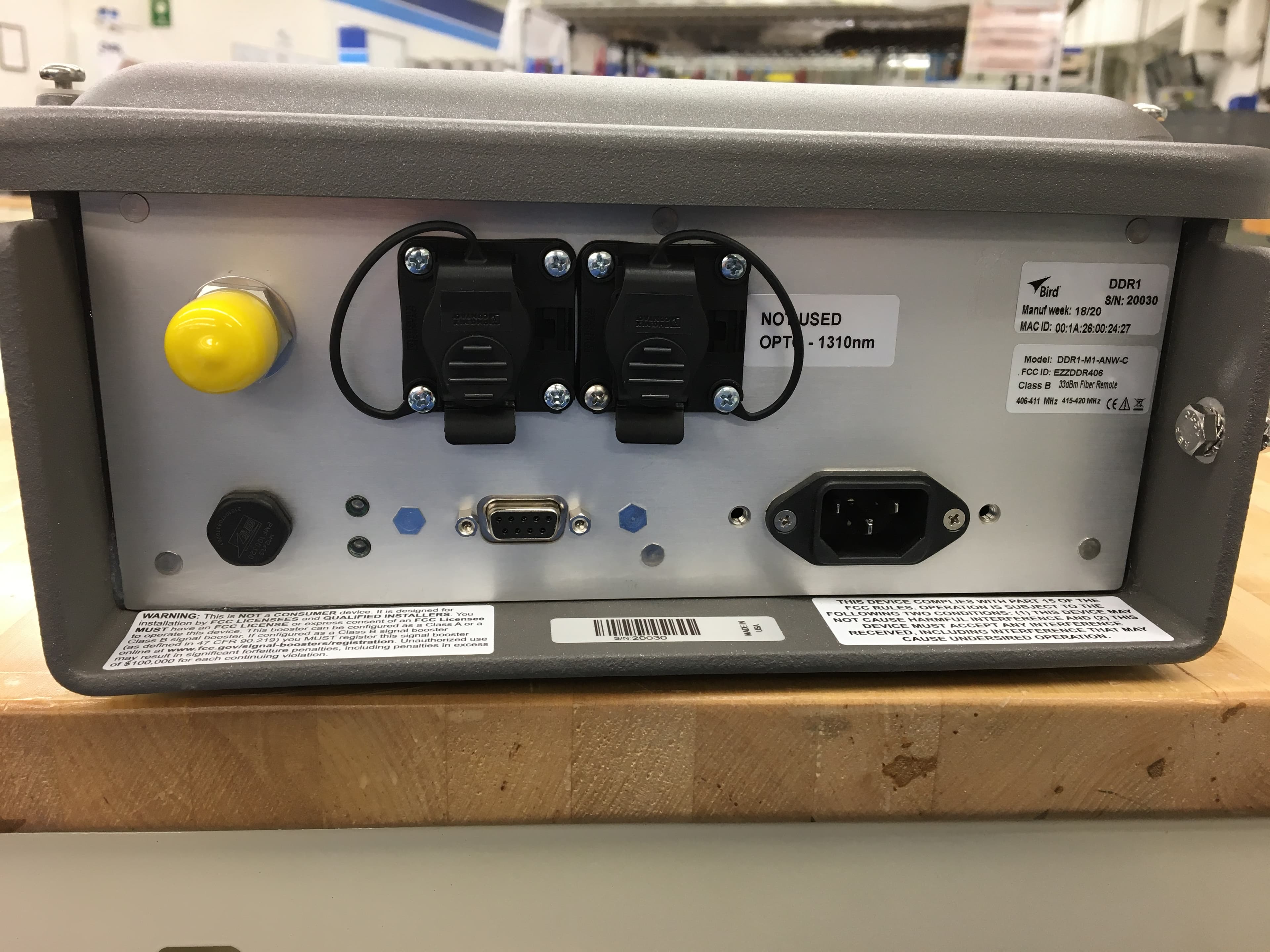
EZZDDR406
Jun 24, 2020DDR Low Band UHF Remote
Equipment Class
B9B - Part 90 Class B Industrial Booster (non-SMR)
EZZ61470
May 19, 2015UHF Digital Signal Booster
Equipment Class
B9A - Part 90 Class A Industrial Booster (non-SMR)
EZZ61470A
May 18, 2015UHF Digital Signal Booster
Equipment Class
B9A - Part 90 Class A Industrial Booster (non-SMR)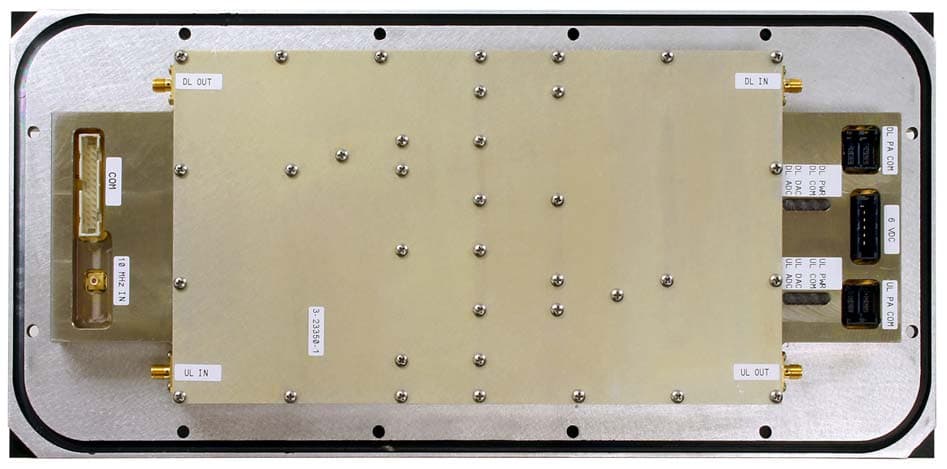
EZZ6138
Sep 21, 2011Channelized Signal Booster
Equipment Class
TNB - Licensed Non-Broadcast Station Transmitter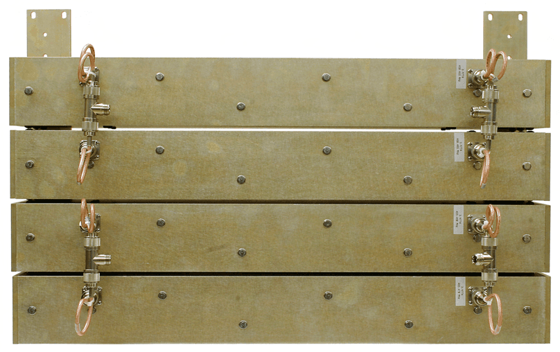
EZZ61170A
Mar 01, 2010Channelized Signal Booster
Equipment Class
TNB - Licensed Non-Broadcast Station Transmitter