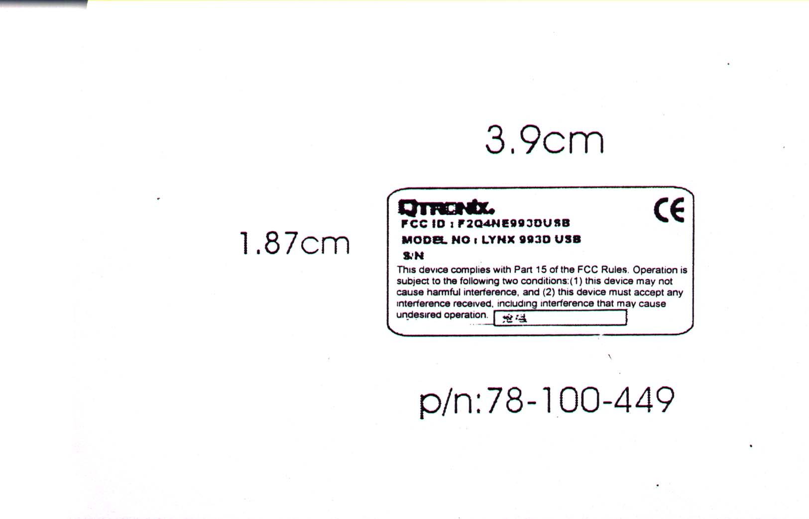
F2Q4NE993DUSB
Ione International Co., Ltd.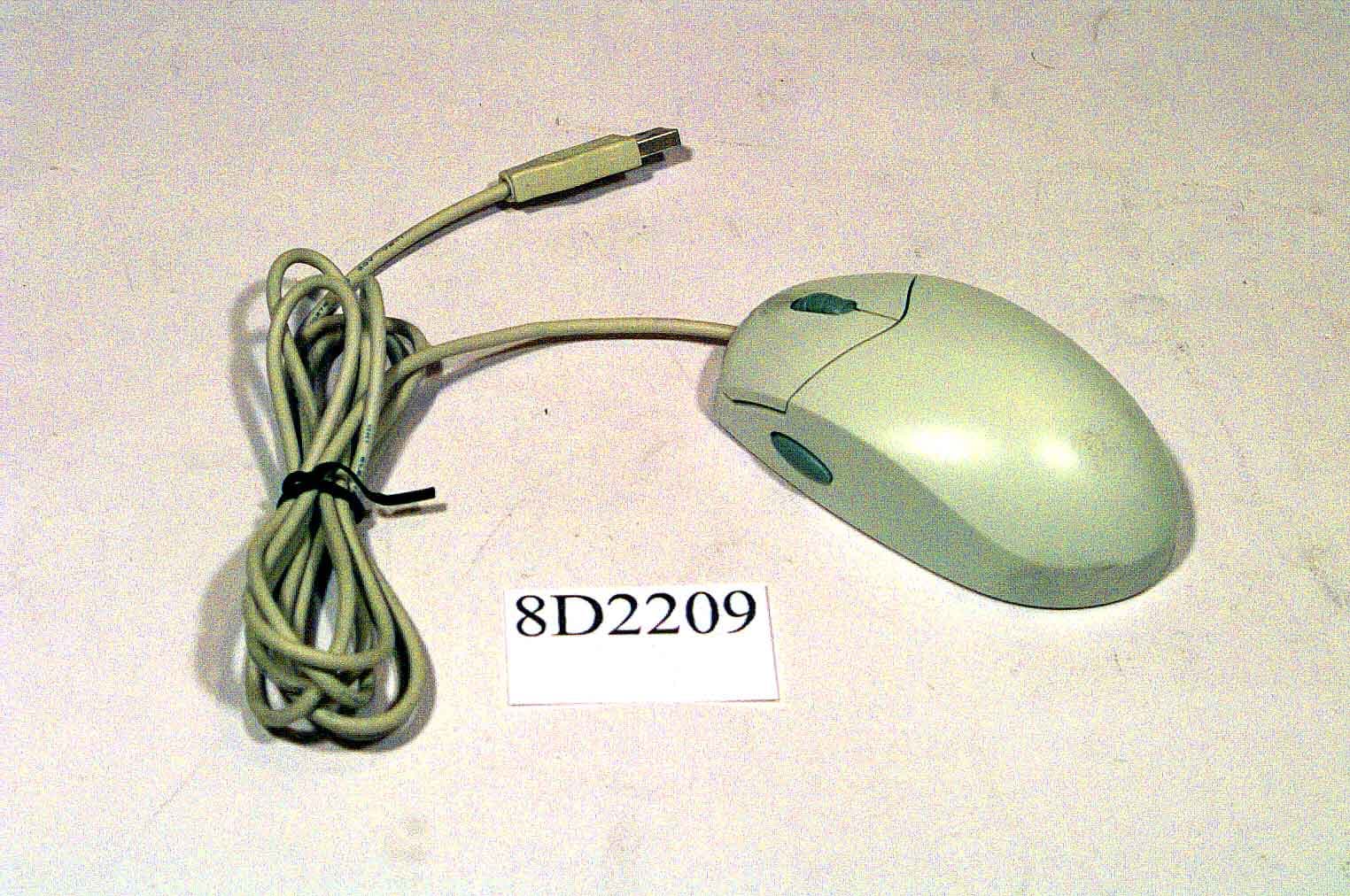
Click to zoom
Application Details
- Equipment Class
- JBP - Part 15 Class B Computing Device Peripheral
- Date of Grant
- Mar 29, 1999
- Application Purpose
- Original Equipment
- Date of Application
- Feb 10, 1999
- Company
- Ione International Co., Ltd.
- Country
- Taiwan
Documents & Files
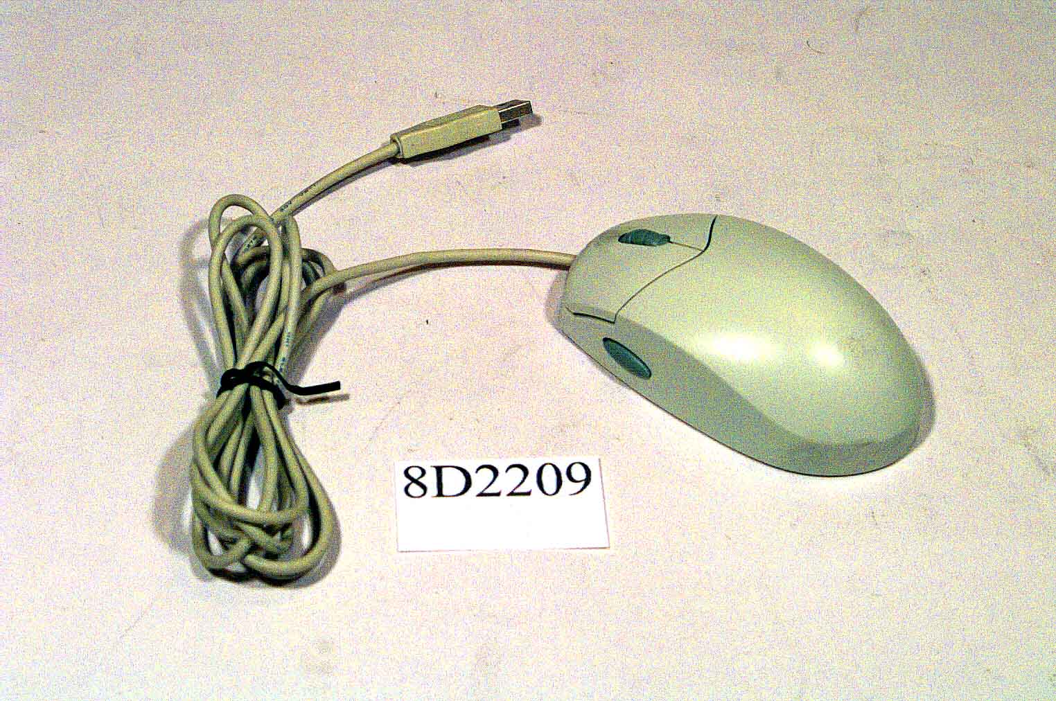
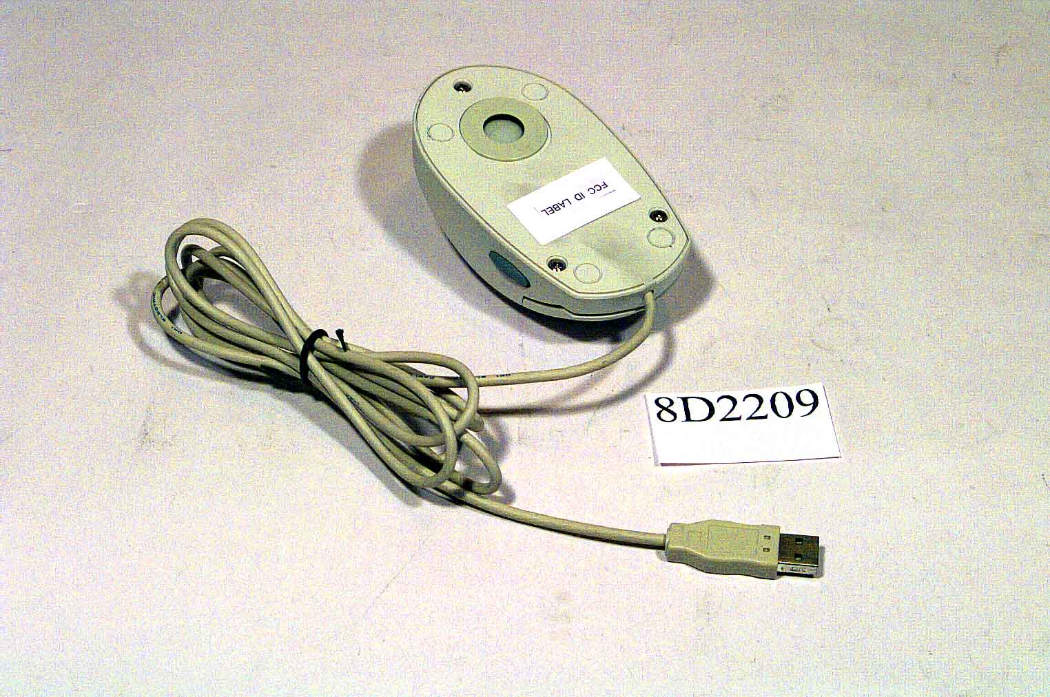
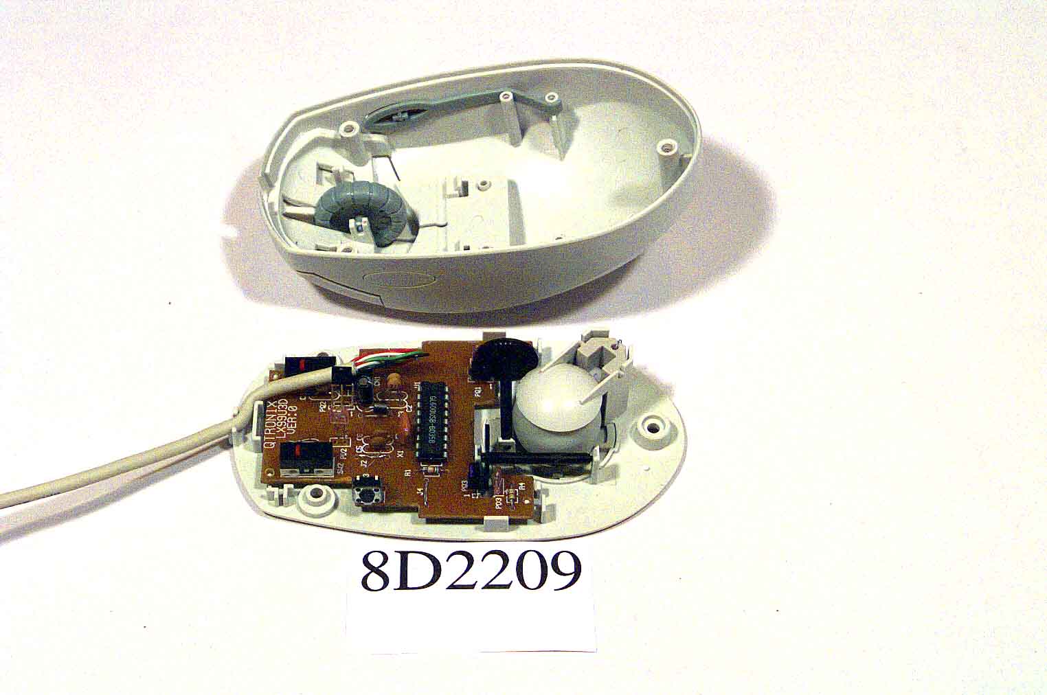
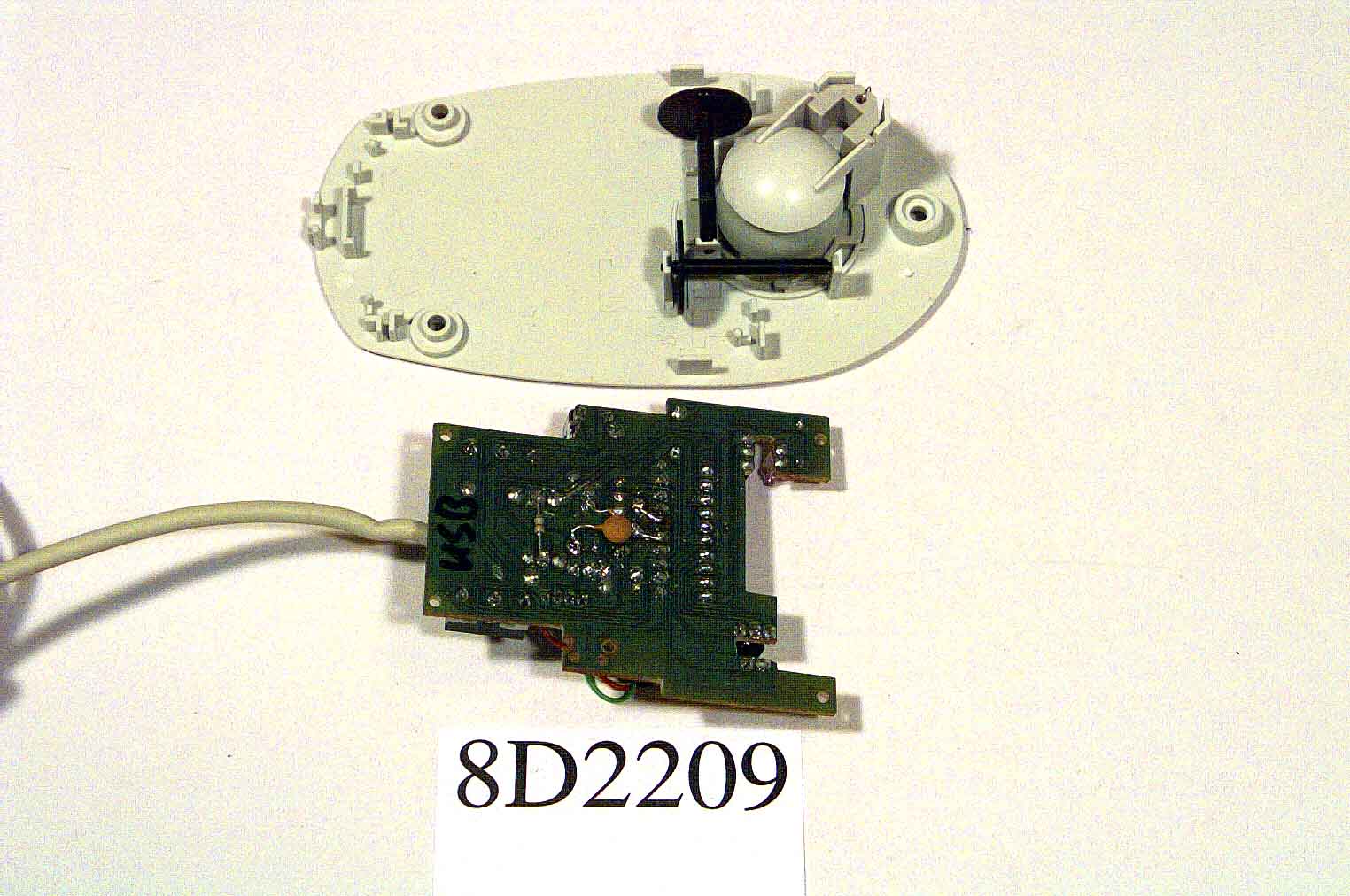
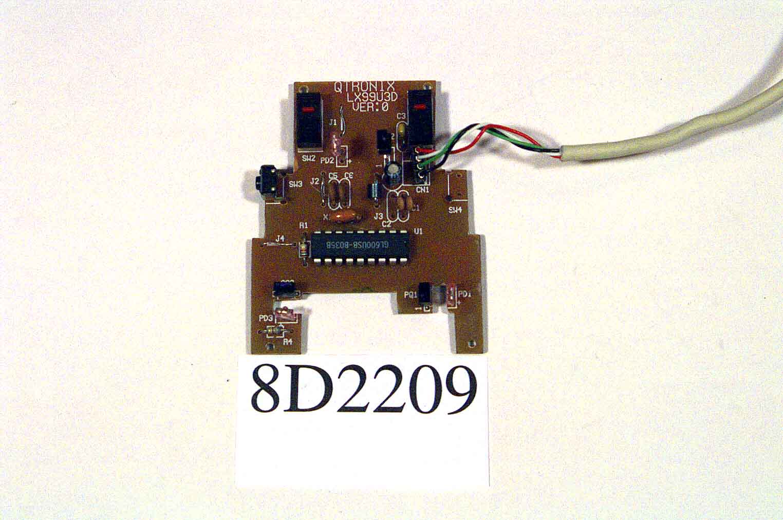
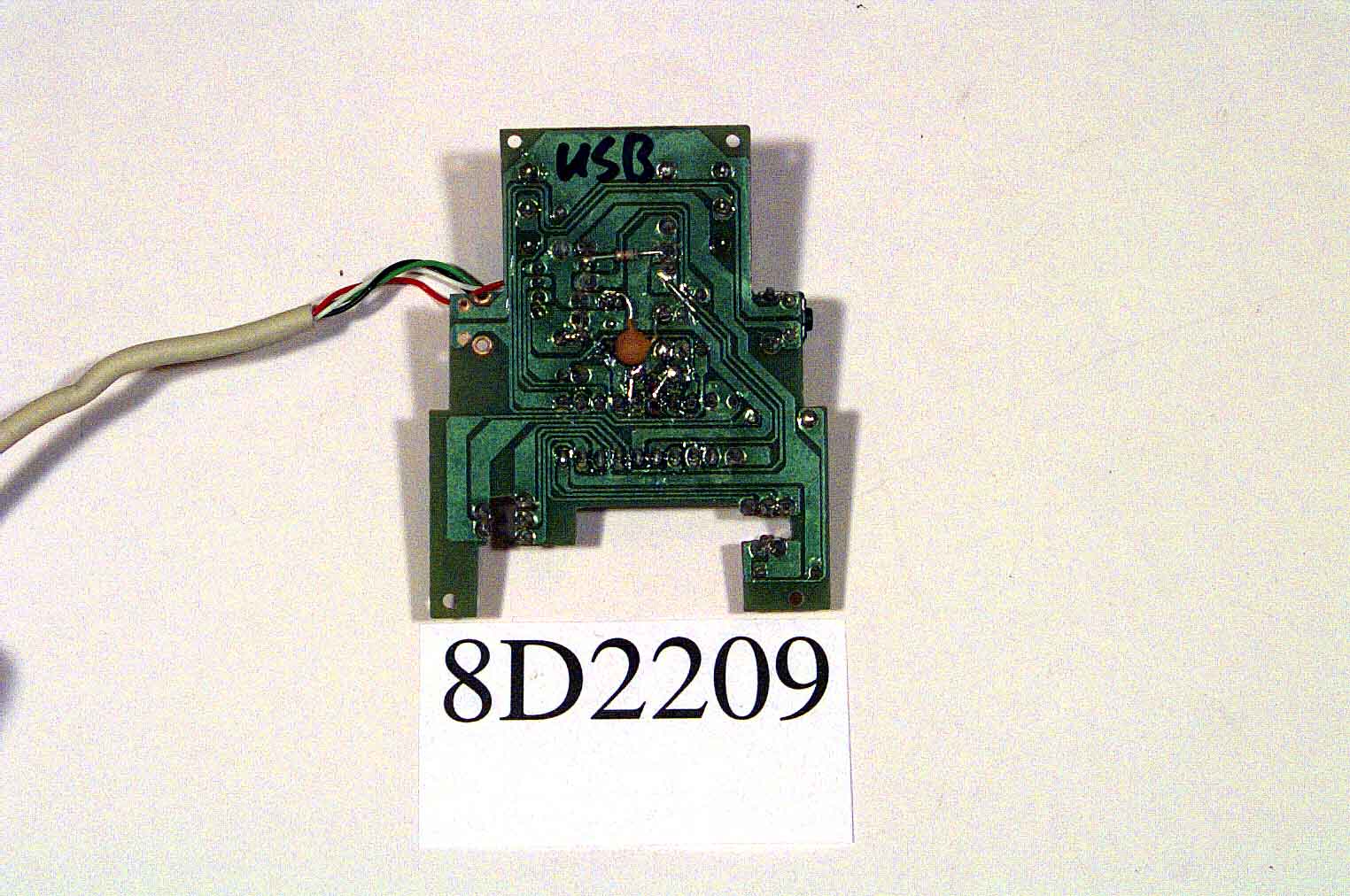
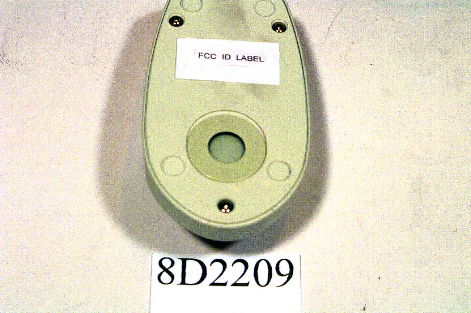
Document Text
Text extracted from the exhibit documents filed with the FCC. Open a document above to read the original.
Users Manual
WARNING Note : This equipment has been tested and found to comply with the limits for a Class B device, pursuant to Part 15 of FCC Rules. These limits are designed to provide reasonable protection against harmful interference in a residential installation. This equipment generates, uses and can radiate radio frequency energy and , if not installed and used in accordance with the instructions, may cause harmful interference to radio communications however , there is no guarantee that interference will not occur in a particular installation. If this equipment does cause harmful interference LYNX 99 3D USB MOUSE LYNX 99 3D USB MOUSELYNX 99 3D USB MOUSE LYNX 99 3D USB MOUSE SPECIFICATIONS SPECIFICATIONSSPECIFICATIONS SPECIFICATIONS FCC ID:F2Q4NE993DUSB DEC, 15, 1998 9F,#75,Sec, 1 Hsin Tai Wu Rd. Hsichih, Taipei Hsien, Taiwan, R.O.C (Far East World Center-Bldg.A) TEL(886-2)2698-2566 FAX(886-2)2698-3133 LYNX 99 /3d USB NET MOUSE SPECIFICATIONS 2 to radio or television reception, which can be determined by turning the equipment off and on , the user is encouraged to try to correct the interference by one or more of the following measures: Reorient or relocate the receiving antenna. Increase the separation between the equipment and receiver. Connect the equipment into an outlet on a circuit different from that to which the receiver in connected. Consult the dealer or an experienced radio / TV technician for technician for help. Notice: Changes or modifications not expressly approved by the part responsible for compliance could void the user’s authority to operate the equipment. SCOPE SCOPESCOPE SCOPE The purpose of this specification is to define the generic operational, Environmental, electrical and mechanical characteristics of the “LYNX 99 / 3D USB Net MOUSE “. GENERAL GENERAL GENERAL GENERAL Description The LYNX 99/3D USB Net MOUSE is designed for use with the Pentium above compatible computers that with a USB connector. It is a 400 dot per inch (DPI) opto-mechanical mouse. A built in microprocessor uses multiple rotary optical encoders and a rubber coated ball to detect mouse movements. Count signals are sent to the host computer where they are translated into motion of the display screen cursor. Interface protocol is provided as follows: Three Button-USB Mouse The interface connection consists of four (4) USB-A plug adapter that is used for Pentium above PC which support USB function. Appearance / Durability This product is intended for user used in home and office environments. Therefore , the quality of appearance and touch are of great importance. Because of the environmental severity of the home and office place, longevity, durability, durability This device complies with Part 15 of the FCC Rules. Operation is Subject to the following two conditions : (1) this device may not cause Harmful interference, and (2) this device must accept any interference Received, including interference that may cause undesired operation. LYNX 99 /3d USB NET MOUSE SPECIFICATIONS 3 and resistance to contamination are also of major concern. Good engineering design practices shall be followed throughout, both mechanically and electrically. Features Unique “No Strain” ergonomic grip and classic style fits perfectly into the hand for a comfortable and attractive feel. Fully compatible with USB For 3D model : MS Wheel Message compatible and Auto Reference compliant. Opto-mechanical technology for highly accurate pointing Highly reliable micro-switched with tactile click sound and feeling Strong point: bundle with scroll-In-Mouse program which make operations more easy and convenient. Package Contents Mouse Driver User manual (or on box) Controller Specifications ParameterMinimumTypicalMaximumUnit Oscillating frequency6-10%66+10%MHz Rising edge crossed width75--300ns Falling edge crossed width75--300ns Mouse CLK active time--83.3--ns Mousse CLK inactive time--83.3--ns Performance specifications Hardware Resolution400dpi Tracking Speed250mm/sec Hysteresis-678 to 678 count for both X, Y axes(unit moves any direction and returns same path. Distance=400 mm, Speed=100+ mm/sec Linear motion accuracy16 x D x sinQ°+15% for both X, Y axes (unit moves any direction. Q = moving angle, D (Distance)=400mm , Speed=100 +5mm/sec EncoderOpto –Mechanical Switch Life1,000,000 cycle life Supply voltage4.0-5.25V Vmas-6.5V Power dissipationMaximum 300mw LYNX 99 /3d USB NET MOUSE SPECIFICATIONS 4 ENVIRONMENTAL SPECIFICATIONS ENVIRONMENTAL SPECIFICATIONS ENVIRONMENTAL SPECIFICATIONS ENVIRONMENTAL SPECIFICATIONS Temperature Operating The operating temperature range shall be from 0 to 70 . There shall be an operational temperature test of a single cycle, ambient, cold, hot, ambient, and ambient, With a minimum of a 15 minute dwell (pause) for every 15 increment of change. The rate of temperature change shall not exceed 20 per hour. The Joystick will operate normally throughout the cycle requiring no operator Intervention or corrective actions, except to cause normal movement. Non-Operating The non-operating temperature range shall be from-65 to 150 . There Shall be a thermal shock test of five(5) cycles from-15 to 55 holding for 30 minutes at each extreme. The rate of temperature change shall not exceed 25 per hour. Normal mouse operation will be verified before and after the thermal shock text. Humidity HumidityHumidity Humidity Operating The operating relative humidity range shall be from10% to 85% non condensing ambient temperature. Non-Operating The non-operating relative humidity range shall be from 10% to 85% non- Condensing. The mouse shall withstand an environment varying between 25 and 55 , 85% relative humidity, non condensing, for a period of 96 hours. Vibration Test (Packaged for shipment) (Packaged for shipment)(Packaged for shipment) (Packaged for shipment) Non-operating 1. 5 to 31 Hz 0.38 mm peak to peak displacement : Continuous logarithmic rates of 0.5 octave / minute back and forth. 2. 32 to 500 …
Text truncated - open the document above for the full version.
Block Diagram
FCC ID:F2Q4NE993DUSB USB MOUSECONNECT ICGL600USB OSCILLATOR X AXISY AXIS KEYBUTTON Lynx 99 3D USB MOUSE 6MHZ Z AXIS
Test Report
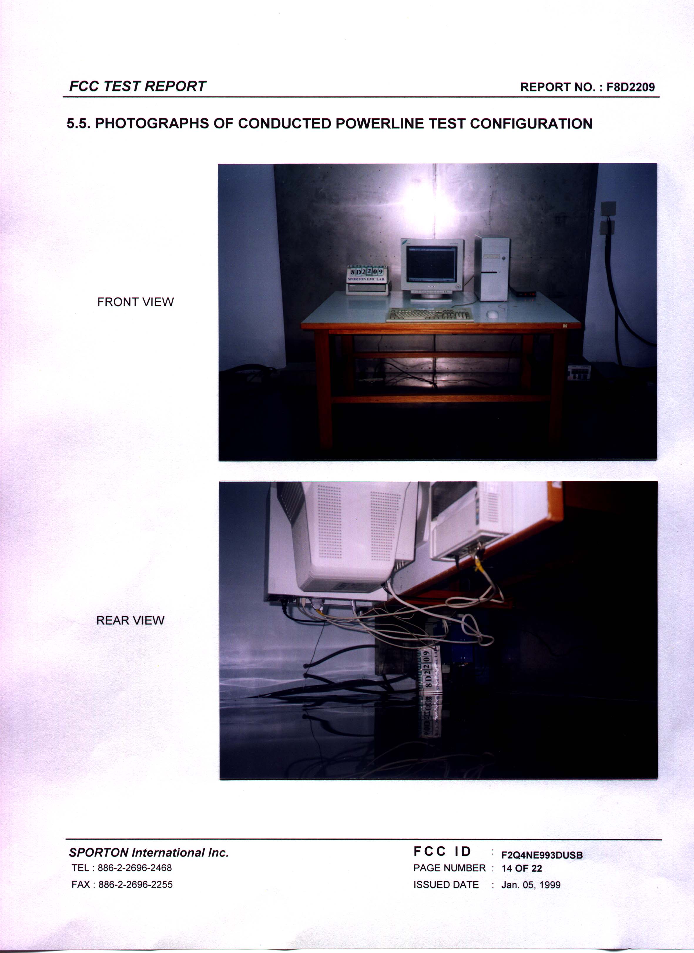
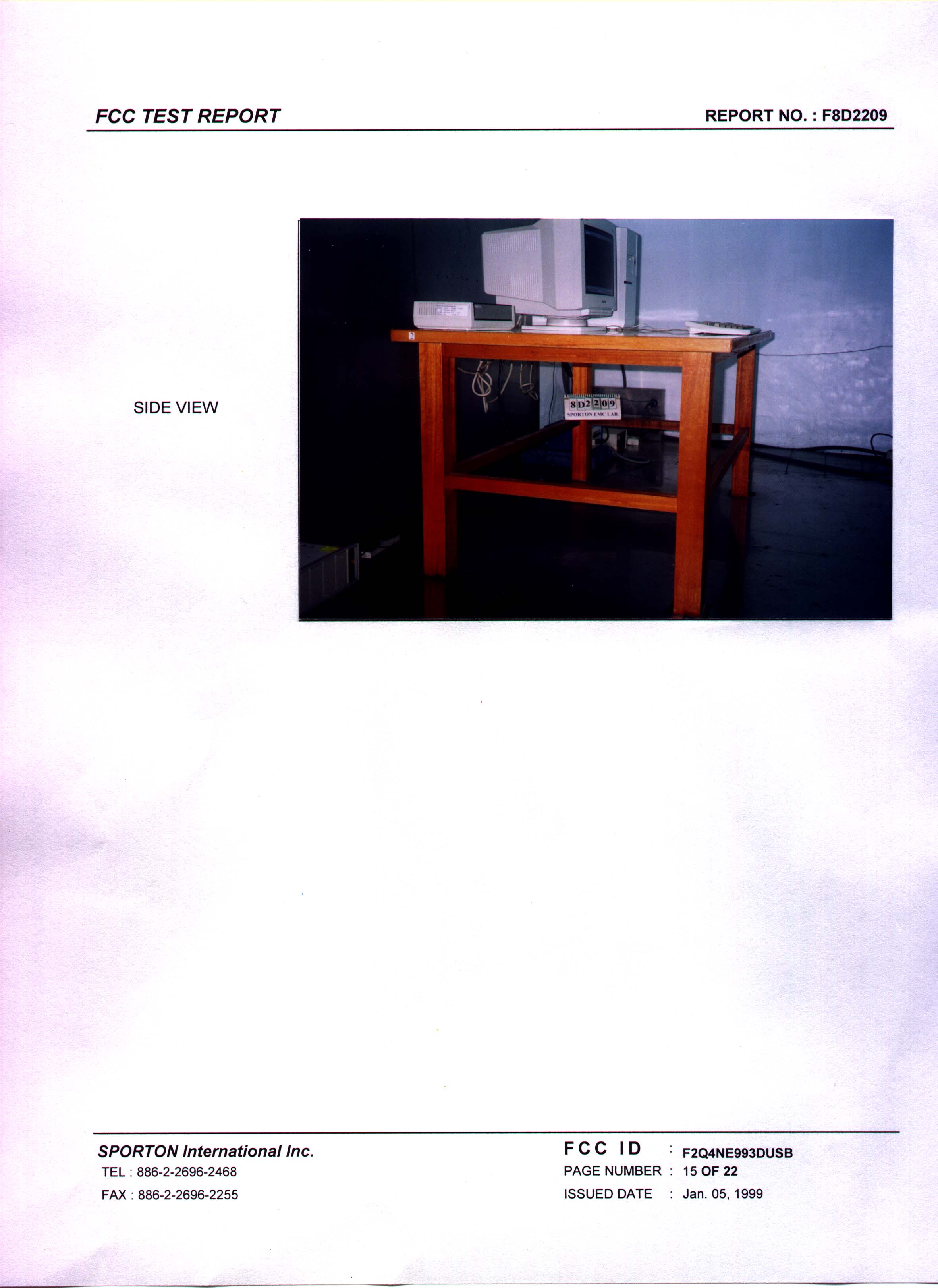
FCC TEST REPORT REPORT NO. : F8D2209 SPORTON International Inc. FCC ID : F2Q4NE993DUSB TEL : 886-2-2696-2468PAGE NUMBER : 1 OF 22 FAX : 886-2-2696-2255ISSUED DATE: Jan. 05, 1999 FCC TEST REPORT for 47 CFR, Part 2, Part 15 and CISPR PUB. 22 EQUIPMENT : MOUSE MODEL NO.: LYNX 99 3D USB FCC ID : F2Q4NE993DUSB FILING TYPE : Original Grant APPLICANT: QTRONIX CORPORATION 9F, #75, Sec. 1, Hsin Tai Wu Rd., Hsichih, Taipei Hsien,Taiwan, R.O.C. z The test result refers exclusively to the test presented test model / sample. z Without the written authorization of the test lab., the Test Report may not be copied. SPORTON INTERNATIONAL INC. 6F, No. 106, Hsin Tai Wu Rd., Sec. 1, Hsi Chih, Taipei Hsien, Taiwan, R.O.C. FCC TEST REPORT REPORT NO. : F8D2209 SPORTON International Inc. FCC ID : F2Q4NE993DUSB TEL : 886-2-2696-2468PAGE NUMBER : 2 OF 22 FAX : 886-2-2696-2255ISSUED DATE: Jan. 05, 1999 TABLE OF CONTENT SECTION TITLEPAGE CERTIFICATE OF COMPLIANCE ............................................................................................................................... 3 1. GENERAL DESCRIPTION OF EQUIPMENT UNDER TEST................................................................................ 4 1.1. APPLICANT ......................................................................................................................................................................................................... 4 1.2. MANUFACTURER .............................................................................................................................................................................................. 4 1.3. BASIC DESCRIPTION OF EQUIPMENT UNDER TEST................................................................................................................................... 4 1.4. FEATURE OF EQUIPMENT UNDER TEST....................................................................................................................................................... 4 2. TEST CONFIGURATION OF EQUIPMENT UNDER TEST ..................................................................................5 2.1. TEST MANNER ................................................................................................................................................................................................... 5 2.2. DESCRIPTION OF TEST SYSTEM..................................................................................................................................................................... 5 2.3. CONNECTION DIAGRAM OF TEST SYSTEM ................................................................................................................................................. 7 3. TEST SOFTWARE ........................................................................................................................................................ 8 4. GENERAL INFORMATION OF TEST ...................................................................................................................... 9 4.1. TEST FACILITY ................................................................................................................................................................................................... 9 4.2. STANDARD FOR METHODS OF MEASUREMENT ........................................................................................................................................ 9 4.3 .TEST IN COMPLIANCE WITH ........................................................................................................................................................................... 9 4.4. FREQUENCY RANGE INVESTIGATED............................................................................................................................................................ 9 4.5. TEST DISTANCE ................................................................................................................................................................................................. 9 5. TEST OF CONDUCTED POWERLINE ................................................................................................................... 10 5.1. MAJOR MEASURING INSTRUMENTS ........................................................................................................................................................... 10 5.2. TEST PROCEDURES......................................................................................................................................................................................... 11 5.3. TYPICAL TEST SETUP LAYOUT OF CONDUCTED POWERLINE.............................................................................................................. 12 5.4. TEST RESULT OF AC POWERLINE CONDUCTED EMISSION ................................................................................................................... 13 5.5. PHOTOGRAPHS OF CONDUCTED POWERLINE TEST CONFIGURATION............................................................................................... 14 6. TEST OF RADIATED EMISSION ............................................................................................................................ 16 6.1. MAJOR MEASURING INSTRUMENTS ........................................................................................................................................................... 16 6.2. TEST PROCEDURES......................................................................................................................................................................................... 17 6.3. TYPICAL TEST SETUP LAYOUT OF RADIATED EMISSION ...................................................................................................................... 18 6.4. TEST RESULT OF RADIATED EMISSION..................................................................................................................…
Text truncated - open the document above for the full version.
Test Report
FEDERAL COMMUNICATIONS COMMISSIONFCC ID:F2Q4NE993DUSB Authorization and Evaluation Division 7435 Oakland Mills Road Columbia, MD 21046 U.S.A. Re: About the modification of MOUSE Gentlemen: I, hereby, declare that all modification on the E.U.T., FCC ID: F2Q4NE993DUSB, will be added or layout on the mass production products. Modifications are shown as below: 1. J3 VCC END is connected to ground with a 33PF capacitor. 2. PD2 + is connected to PQ2 VCC pin with a 680 resister. Sincerely yours John Lee Eleotronic Engineer
Contact Information
Applicant
Ming Wang(Electronic Engineer Supervisor)
Technical Contact
SPORTON INTERNATIONAL INC.Kathy Lin
[email protected]886-2-2696-2468
6F, No. 106, Sec. 1, Hsin Tai Wu Rd., Hsi Chin, · Taiwan
Non-Technical Contact
SPORTON INTERNATIONAL INC.Kathy Lin
[email protected]718-468-4260
Test Firm
Sporton International Inc.W. Huang
Technical Specifications
| # | Rule Parts | Frequency Range | Power Output |
|---|---|---|---|
| 1 | 15B | - | - |
Other Applications from Ione International Co., Ltd.
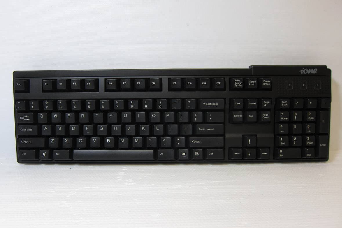
F2QSCORPIUSU9WL
May 02, 2011Wireless Keyboard
Equipment Class
DXX - Part 15 Low Power Communication Device Transmitter
F2QRFLIBRA-S10HU
Dec 09, 2010Wireless Presenter Mouse
Equipment Class
DXX - Part 15 Low Power Communication Device Transmitter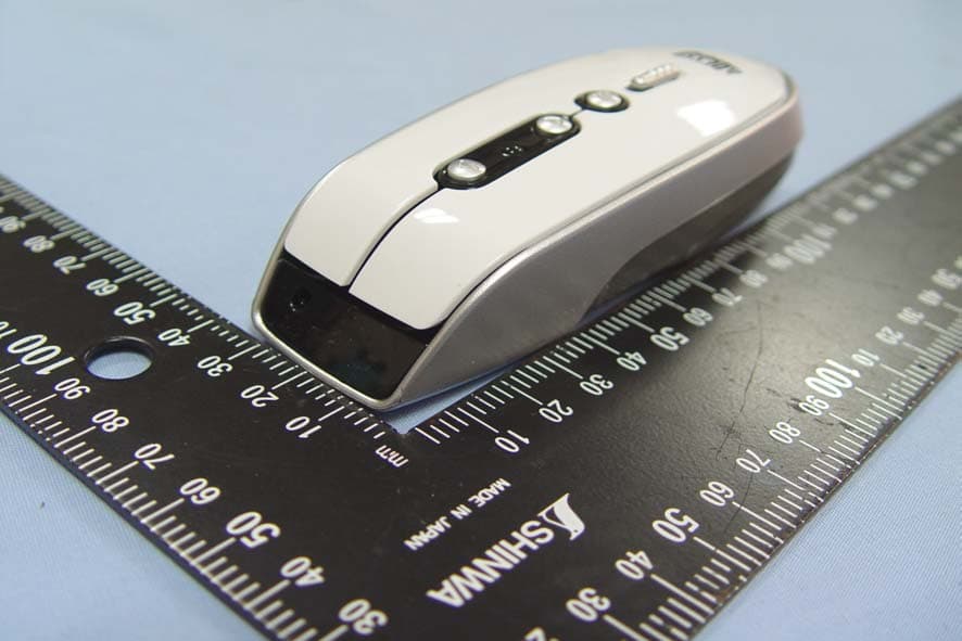
F2QRFLYNXP2
Sep 08, 2010Wireless mouse
Equipment Class
DXX - Part 15 Low Power Communication Device Transmitter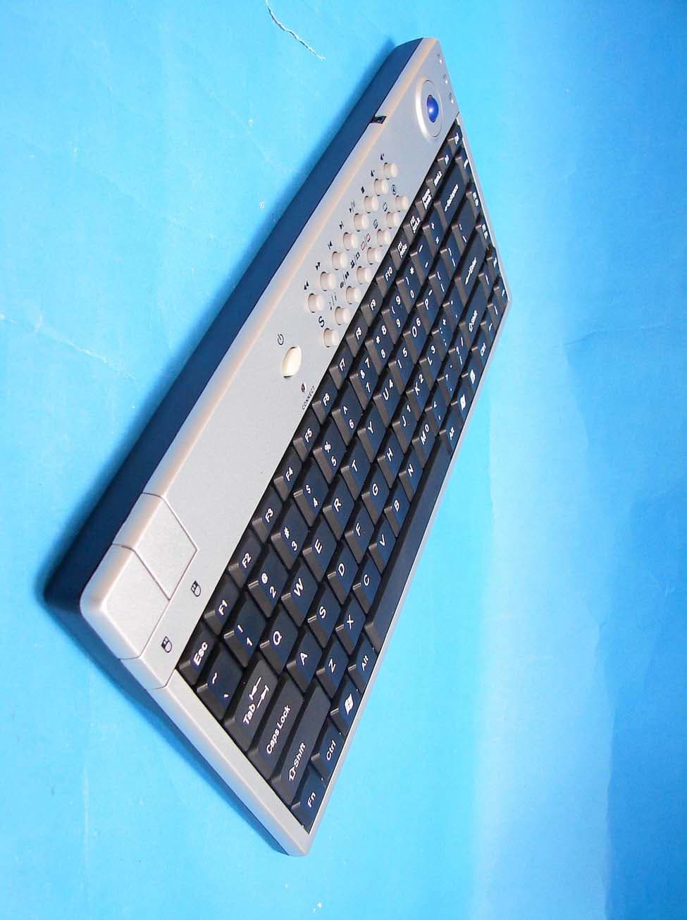
F2QSCORPIUSP20MTU
Jul 01, 20072.4 GHz MCE Keyboard with Optical Trackball
Equipment Class
DXX - Part 15 Low Power Communication Device Transmitter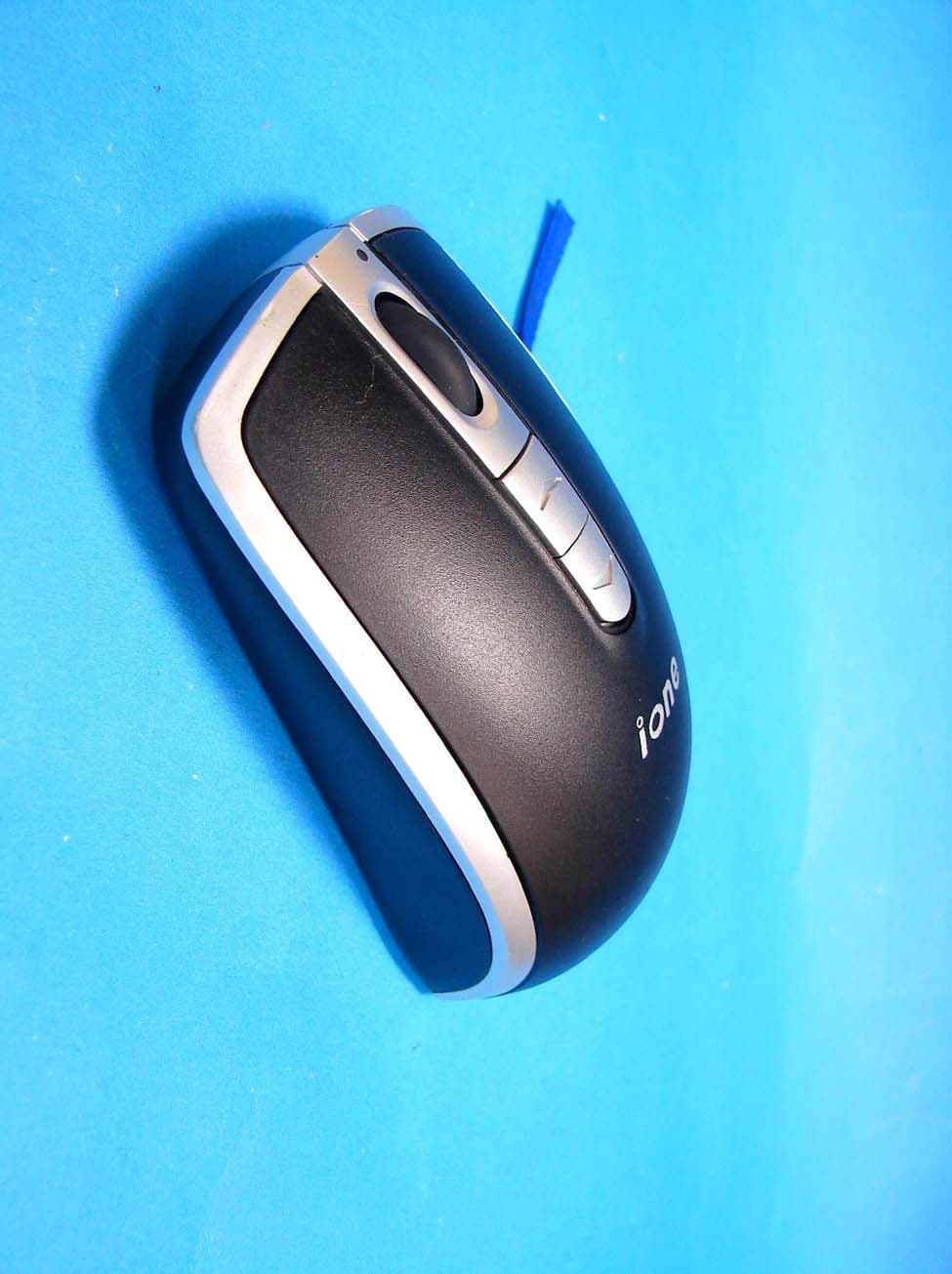
F2QLYNXR7AU
Apr 08, 200727MHz OPTICAL MOUSE
Equipment Class
DXX - Part 15 Low Power Communication Device Transmitter