F2Q96C96001M7WIRELESS OPTICAL MOUSE
Ione International Co., Ltd.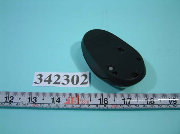
Click to zoom
Application Details
- Equipment Class
- DXX - Part 15 Low Power Communication Device Transmitter
- Date of Grant
- Jun 25, 2003
- Application Purpose
- Original Equipment
- Date of Application
- Jun 25, 2003
- Equipment Note
- WIRELESS OPTICAL MOUSE
- Frequency Range
- 27.04000000 - 27.05000000
- Company
- Ione International Co., Ltd.
- Country
- Taiwan
Documents & Files
Document Text
Text extracted from the exhibit documents filed with the FCC. Open a document above to read the original.
Users Manual
A. Quick Reference Guide for RF Wireless Mouse Thank you for purchasing the RF wireless Mouse. This features of the mouse have three keys and twenty self setting programmable functions. This guide gives you what you need to get started right away. After you have finished installation, refer to the electronic user’s guide on the software driver to learn more about your product. Please follow the instructions below: I. Components and Features: 1. Features: RF wireless mouse Advance 3 buttons design with ergonomic styling Security ID: 256 set ID 21 different multimedia functions 2. Package Contents: RF wireless Mouse Receiver 2AA batteries Driver Diskette USB extended line UP Adaptor II. Hardware Installation 1. Turn off your computer. 2. Insert the mouse connector PS2 (or USB) to PC Mouse port 3. Insert batteries Insert provided batteries in mouse. Refer to diagram inside battery compartment. 4. Power on your computer III. ID Set IV. Software Installation: Turn on your computer and run either Windows 98 / 2000 / ME / XP. 1. Insert the program setup disk into driver A (or B). 2. Start Execute A:\SETUP.EXE Choose " Extract" Choose "USB or PS2" port “OK”. 3. Follow the setup program's on-screen instructions. (Below is the setup process. Please follow the screens to install.) 4. Programmable functions menu: Reset ID before using Step 1: Connect the receiver to your computerStep 2: Push the “CONNECT” button on the receiver. The LED will start to blink. Step 3: Push the button on the back of the mouse (in upper left corner). Pleasenote that this step must be completedafter Step 2 within 8 seconds. Step 4: When the rece iver and the mouse are connected, the LED will blink faster fora while, it means the set has beencompleted. Step 5: Please go back to Step 2 if the LED does not behave as that in Step 4. Note: If same ID is used by other users and causes interference, just repeat thisreset procedure. RF Lynx Mouse & RF Lynx Receiver Lynx-MVII & Lynx-MVII-R User’s Manual 1 2 25-100-566 B. TROUBLE SHOOTING GUIDE Symptom Possible Reason Remedy Can’t recognize the device or the device can’t work. You plug the device to a USB Hub without power support. Plug the device to PC host port or a USB Hub with power support. Device can’t work after the driver beinstalled or removed. The Driver be installed or removed. Reboot the PC. T he function of software is not work. Function error. Re-install the software or refer the User Guide. Quick Start, User Manuals, or Help files on the CD do not open. Internet Explorer 4.0 orMicrosoft or Netscape Communicator 4.0 are not installed. T o view all CD ROM materials, you must have InternetExplorer or Netscape Navigator/Communicator version 4.0 or higher. NOTE This equipment has been tested and found to comply with the limits for a Class B digital device, pursuant to Part 15 of the FCC Rules. These limits are designed to provide reasonable protection. This equipment generates, uses and can radiated radio frequency energy and, if not installed and used in accordance with the instructions, may cause harmful interference to radio communications. However, there is no guarantee that interference will not occur in a particular installation If this equipment does cause harmful interference to radio or television reception, which can be determined by turning the equipment off and on, the user is encouraged to try to correct the interference by one or more of the following measures: -Reorient or relocate the receiving antenna. -Increase the separation between the equipment and receiver. -Connect the equipment into an outlet on a circuit different from that to which the receiver is connected. -Consult the dealer or an experienced radio/TV technician for help. Changes or modifications not expressly approved by the party responsible for compliance could void the user‘s authority to operate the equipment. Close Window : Close the upper windows. Maximize Window : Maximize the upper windows. Minimize Window : Minimize the upper windows. Restore Window : Restore Window. Cut (Ctrl+X) : Cut. Copy (Ctrl+C) : Copy. Paste (Ctrl+P) : Paste. Internet Explorer : Open the Internet Explorer directly when you have setthe Explorer. Internet Mail : Open the Internet mail directly when you have setting the E-mail. Control Panel : Open Control Panel easily. File Manager : Open File Manager (Windows Explorer) easily. CD Player : It will play audio CD, when there is one audio CD in CD-ROM drive. Media Player : It will play VCD, when there is one VCD in CD-ROM drive and your system has installed MPEGcard or MPEG software. Calculator : Open Calculator. Word Pad : Open Word Pad. Dos Prompt : Open DOS prompt. Task List : Open Task List easily. Zoom In : Zoom lens enlarge the screen picture or text, Click right button can change Zoon-in size in cycle. Auto Scrolling : There is a four-direction arrows on screen when you on a document which can be four direction scrolling. Move mouse to control scrolling direction. Shut Down : Shut down the PC. 3
Block Diagram
FCC ID: F2Q96C96001M7 RF Lynx Mouse, Lynx-MVII ADNS6030 18.432MHz ANT SENSOR 3 BUTTON WHELL ID BUTTON MA60H221S 27.042MHz 76.6KHz
Cover Letter(s)
Date: April 15, 2003 Re: Renew company and brand name Dear Sirs, We, Qtronix Corporation, have changed our company name as follows: FRN 0007901788 Grantee Code F2Q Old Name Qtronix Corporation New Name Itron Technology Inc. Reason for Name Change Simply change the company name Contact Name Phil Kao Contact Title Product Engineer Telephone Number 886-2-26982566 Fax Number 886-2-26983133 E-mail Adress The new CIS Itron takes place with immediate effect. With best regards, Phil Kao, Product Engineer Itron Technology Inc.
External Photos
FCC ID: F2Q96C96001M7 NUMBER 1 FRONT SIDE OF EUT FCC ID: F2Q96C96001M7 NUMBER 2 REAR SIDE OF EUT
ID Label/Location Info
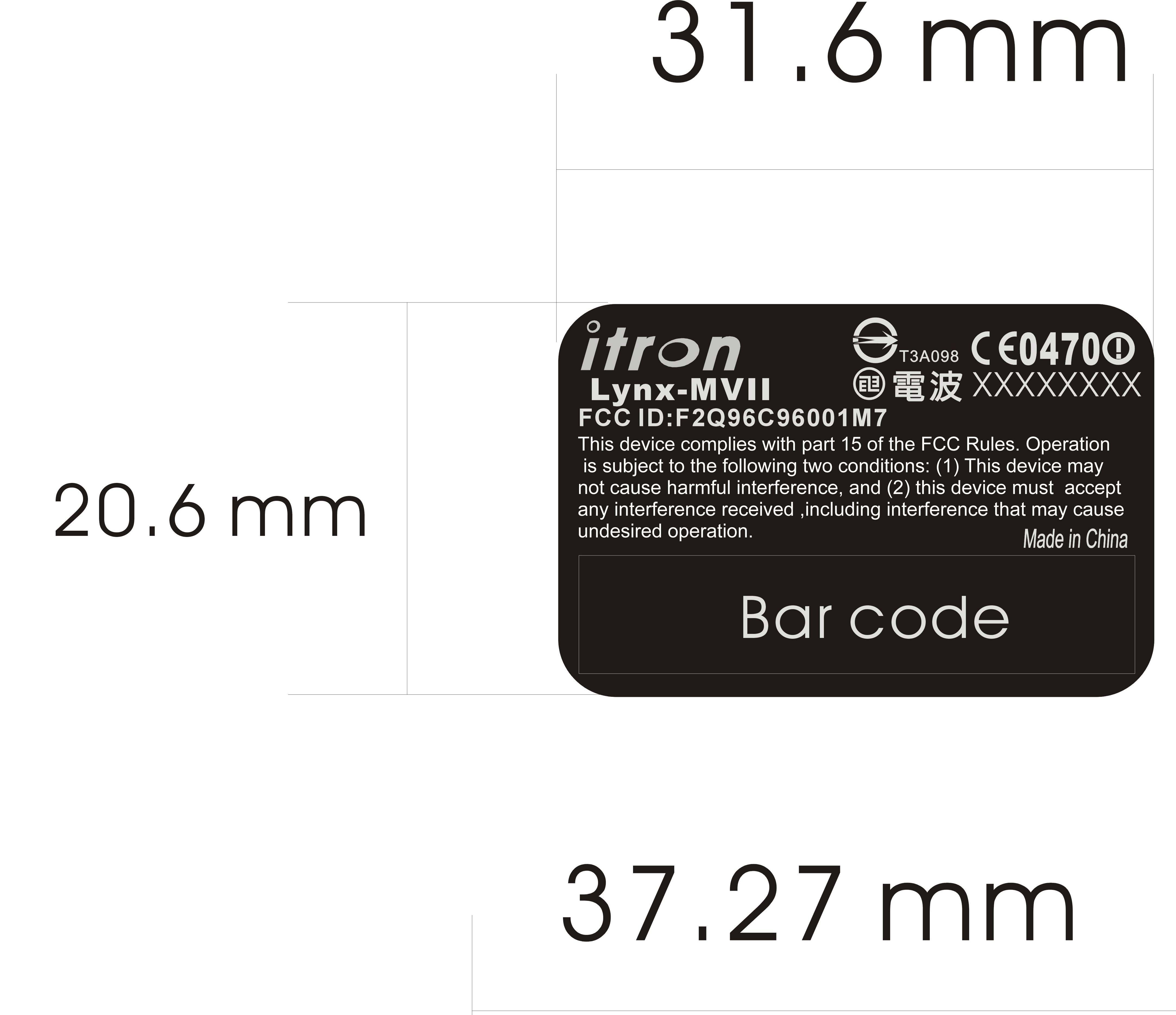
FCC ID: F2Q96C96001M7 Label Location
Internal Photos
FCC ID: F2Q96C96001M7 Number 1 MECHANICAL CONSTRUCTION FCC ID: F2Q96C96001M7 Number 2 MECHANICAL CONSTRUCTION FCC ID: F2Q96C96001M7 Number 3 MECHANICAL CONSTRUCTION FCC ID: F2Q96C96001M7 Number 4 FRONT SIDE OF MAIN BOARD FCC ID: F2Q96C96001M7 Number 5 REAR SIDE OF MAIN BOARD
Operational Description
Illustration for Wireless Optical Mouse Model: RF Lynx Mouse; Lynx-MVII FCC ID: F2Q96C96001M7 Wireless Optical Mouse (Model: RF Lynx Mouse; Lynx-MVII) is designed to work as a input and pointing device of PC (or Notebook). When pushing or moving buttons of Mouse, signals go into ADNS6030 and MA60H221S CHIP. After modulates, signals be emitted the radio frequency at 27.045 MHz through an antenna. Receiver captures the radio frequency through antenna. MC3361 CHIP of receiver receives and demodulates the signals, then sends data to MA606 CHIP. After processing, data go into PC through USB connector. Thus, an action of RF MOUSE is completed.
Schematics
FCC ID: F2Q96C96001M7 Mouse: RF Lynx Mouse, Lynx-MVII 0 0 0 00 0 0 0 0 00 0 0 0 0 0 VDD 0 00 0 VDD VBT+ VBT+ 0 0 0 SCLK PD SCLKSDIO SDIOPD MA60H221S U2 123456789 1011121314 1516171819202122232425262728 OSC1VSSOSC2VDDRBUTMBUTLBUTRFOUTORFIN0ORFIN1ORFOTXDPDWA WB Z1INZ2IN SDIO SCLK BATL TYPE TXCB BBUTFBUT SVDIN DCVR VL VL_NM X4 18.432MHz LED1 C133P C6P +-5% R110M C233P X1 76.8K + C17100uF C83P +-0.25PF + C1610uF R6 560 OHM LED2 X3 OPEN C433PF +-5% C533P +-5% R11 OPEN R10 C2410nF R3 R +-1% R2 240K +-1% R8 15K Q1RB421 C14104 R70 OHM C15104 ADNS-2030U1 12345678 910111213141516 SCLKXAXBYBYAXY_LEDREFAREFB OSC_IN GND OSC_OUT GND VDD R_BIN PD SDIO SWSG1SW ENCODER R4 1.2M C18104 L382uH C20104 --- VBAT UM-4(X2) R5 680K L1 1.8uH L20.82uH SW2SW1SW3 C11 22P +-5% C10 22P C975P +-5% L4OPEN + C19100uF C12 OPEN C30.1uF X2 27.042MHz 20PPM 18PF SW4 SWID Q3 OPEN 3 2 1 + C1310uF PCBANT S G D 0 OHM X2 C6 22P X2 C6 27P OPEN TP1TP2TP3 TP4 TP5 TP6 TP7TP8 TP10 TP9 FOR 2051 R:MA6022 IC 100K,110K,120K
Test Report
FCC TEST REPORT Report No. : F342302 SPORTON International Inc. TEL : 886-2-2696-2468 FAX : 886-2-2696-2255 FCC TEST REPORT for 47 CFR, Part 15, Subpart C Equipment : Wireless optical mouse Model No. : RF Lynx Mouse, Lynx MVII FCC ID : F2Q96C96001M7 Filing Type : Certification Applicant : Itron Technology Inc. 9F, #75, Sec, 1, Hsin Tai Wu Rd., Hsichih, Taipei Hsien, Taiwan, R.O.C. The test result refers exclusively to the test presented test model / sample. Without written approval of SPORTON International Inc., the test report shall not be reproduced except in full. Certificate or Test Report must not be used by the applicant to claim the product in this test report endorsement by NVLAP or any agency of U.S. government. SPORTON International Inc. 6F, No.106, Sec. 1, Hsin Tai Wu Rd., Hsi Chih, Taipei Hsien, Taiwan, R.O.C. FCC TEST REPORT Report No. : F342302 SPORTON International Inc. FCC ID : F2Q96C96001M7 TEL : 886-2-2696-2468 Page No. : i FAX : 886-2-2696-2255 Issued Date : May 26, 2003 Table of Contents History of this test report....................................................................................................................................ii CERTIFICATE OF COMPLIANCE........................................................................................................................1 1. General Description of Equipment under Test.............................................................................................2 1.1. Applicant..........................................................................................................................................................................................2 1.2. Manufacturer ...................................................................................................................................................................................2 1.3. Basic Description of Equipment under Test ....................................................................................................................................2 1.4. Feature of Equipment under Test ...................................................................................................................................................2 2. Test Configuration of Equipment under Test ...............................................................................................3 2.1. Test Manner ....................................................................................................................................................................................3 2.2. Description of Test System .............................................................................................................................................................3 2.3. Band edge compliance plot per 15.227(b). .....................................................................................................................................5 2.4. Connection Diagram of Test System ..............................................................................................................................................7 3. General Information of Test............................................................................................................................8 3.1. Test Facility .....................................................................................................................................................................................8 3.2. Test Voltage ....................................................................................................................................................................................8 3.3. Standard for Methods of Measurement...........................................................................................................................................8 3.4. Frequency Range Investigated .......................................................................................................................................................8 3.5. Frequency Range Investigated .......................................................................................................................................................8 3.6. Test Distance ..................................................................................................................................................................................8 4. Test of Conducted Powerline .........................................................................................................................9 5. Test of Radiated Emission............................................................................................................................10 5.1. Major Measuring Instruments........................................................................................................................................................10 5.2. Test Procedures ............................................................................................................................................................................11 5.3. Typical Test Setup Layout of Radiated Emission..........................................................................................................................12 5.4. Test Result of Radiated Emission .................................................................................................................................................13 6. EMI Suppression Component List ...............................................................................................................17 7. Antenna Factor & Cable Loss ......................................................................................................................18 8. List of Measuring Equipments Used ...........................................................................................................19 9. Uncertainty of Test Site ...............…
Text truncated - open the document above for the full version.
Test Setup Photos
FCC TEST REPORT Report No. : F342302 SPORTON International Inc. FCC ID : F2Q96C96001M7 TEL : 886-2-2696-2468 Page No. : 1 of 1 FAX : 886-2-2696-2255 Issued Date : May 26, 2003 1.1. Photographs of Radiated Emission Test Configuration The photographs show the configuration that generates the maximum emission. FRONT VIEW REAR VIEW
Contact Information
Applicant
Ming Wang(Electronic Engineer Supervisor)
Test Firm
Sporton International Inc.Kathy Lin
Technical Specifications
| # | Rule Parts | Frequency Range | Power Output |
|---|---|---|---|
| 1 | 15C | 27.04 MHz - 27.05 MHz | - |
Other Applications from Ione International Co., Ltd.
F2QSCORPIUSU9WL
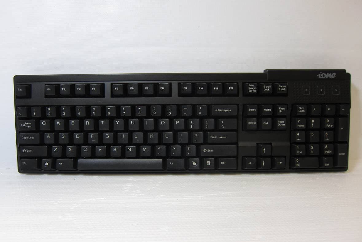
May 02, 2011Wireless Keyboard
Equipment Class
DXX - Part 15 Low Power Communication Device Transmitter
F2QRFLIBRA-S10HU
Dec 09, 2010Wireless Presenter Mouse
Equipment Class
DXX - Part 15 Low Power Communication Device Transmitter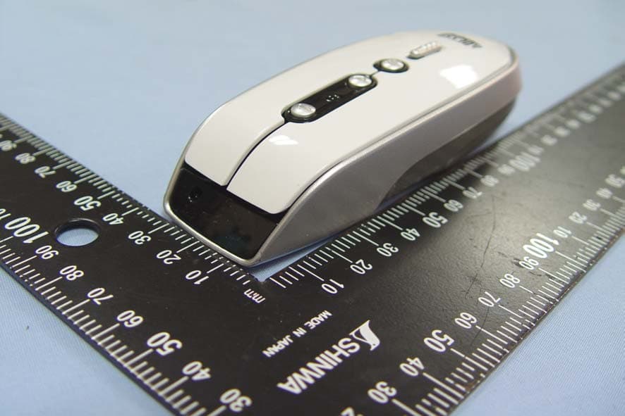
F2QRFLYNXP2
Sep 08, 2010Wireless mouse
Equipment Class
DXX - Part 15 Low Power Communication Device Transmitter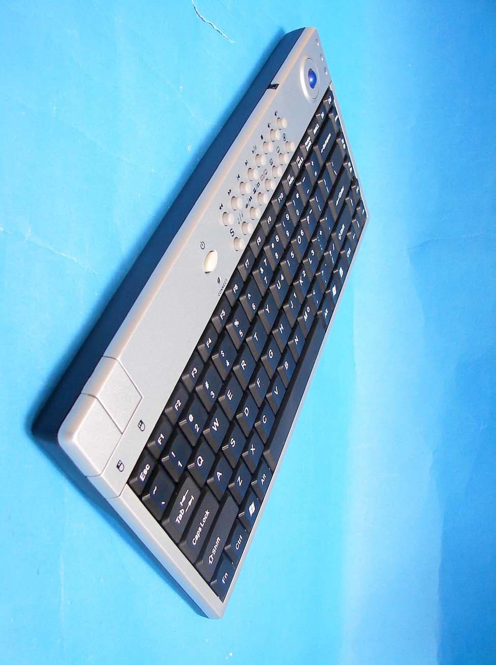
F2QSCORPIUSP20MTU
Jul 01, 20072.4 GHz MCE Keyboard with Optical Trackball
Equipment Class
DXX - Part 15 Low Power Communication Device Transmitter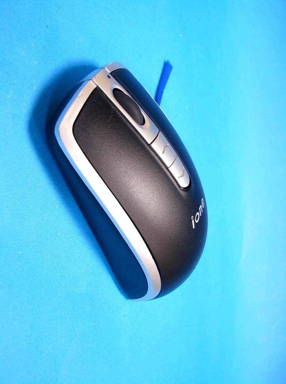
F2QLYNXR7AU
Apr 08, 200727MHz OPTICAL MOUSE
Equipment Class
DXX - Part 15 Low Power Communication Device Transmitter