F2QRFCOMPOTXRF Mouse
Ione International Co., Ltd.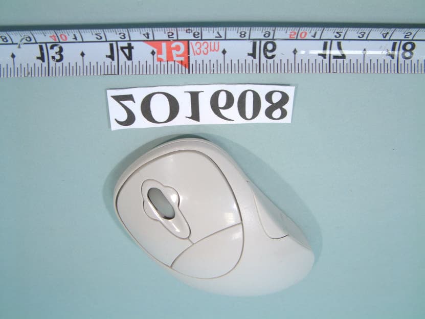
Click to zoom
Application Details
- Equipment Class
- DXX - Part 15 Low Power Communication Device Transmitter
- Date of Grant
- Jan 26, 2003
- Application Purpose
- Original Equipment
- Date of Application
- Jan 26, 2003
- Equipment Note
- RF Mouse
- Frequency Range
- 26.96000000 - 27.28000000
- Company
- Ione International Co., Ltd.
- Country
- Taiwan
Documents & Files
Document Text
Text extracted from the exhibit documents filed with the FCC. Open a document above to read the original.
Users Manual
` Messrs: User’s Guide FCC ID: F2QRFCOMKBTX / KEYBOARD: SCORPIUS RF/SCORPIUS MVII/SCORPIUS KIV FCC ID: F2QRFCOMPOTX / MOUSE: LYNX RF /LYNX KIV/LYNX LV/LYNX KV RECEIVER: RECEIVER RF/RECEIVER KI PM: Electronic Engineer: Mechanical Engineer: Produce by: Email Address: [email protected] World Wide Web: http://www.qtronix.com.tw 9F, # 75, Se . 1, Hsin Tai Wu Rd. Hsichih, Taipei Hsien,Taiwan, R.O.C.(Far East World Center-Bldg. A) Tel: (886-2) 2698-2566 Fax: (886-2)2698-3133 QTRONIX CORPORATION C Approval Signatures: Scorpius KIV (P) & Lynx KIV (p) SPECIFICATIONS 2 WARNING Note: This equipment has been tested and found to comply with the limits for a Class B digital device, pursuant to Part 15 of the FCC Rules. These limits are designed to provide reasonable protection. This equipment generates, uses and can radiated radio frequency energy and, if not installed and used in accordance with the instructions, may cause harmful interference to radio communications. However, there is no guarantee that interference will not occur in a particular installation If this equipment does cause harmful interference to radio or television reception, which can be determined by turning the equipment off and on, the user is encouraged to try to correct the interference by one or more of the following measures: -Reorient or relocate the receiving antenna. -Increase the separation between the equipment and receiver. -Connect the equipment into an outlet on a circuit different from that to which the receiver is connected. -Consult the dealer or an experienced radio/TV technician for help. Changes or modifications not expressly approved by the party responsible for compliance could void the user‘s authority to operate the equipment. This device complies with Part 15 of the FCC Rules. Operation is subject to the following two conditions:(1) this device may not cause harmful interference, and (2) this device must accept any interference received, including interference that may cause undesired operation. Scorpius KIV (P) & Lynx KIV (p) SPECIFICATIONS 3 Setup Guide Reset ID before using Step 1: Connect the receiver to your computer Step 2: Push the “CONNECT” button on the receiver. Step 3: Push the button on the back of the mouse (in upper left corner). Please note that this step must be completed after Step 2 within 8 seconds. Step 4: Move pointer,when the receiver and the mouse are connected, the LED will blink , the setting has been completed. Step 5: Please go back to Step 2 if the LED does not behave as that in Step 4. Step 6: Push the “CONNECT” button on the receiver. Step 7: Push the button on the back of the keyboard (in upper left corner). Please note that this step must be completed after Step 6 within 8 seconds. Step 8: Push “Space” key ,when the receiver and the keyboard are connected, the LED will blink , the setting has been completed. Note: If same ID is used by other users and causes interference, just repeat this reset procedure. Scorpius KIV (P) & Lynx KIV (p) SPECIFICATIONS 4 GENERAL Description keyboard has an enhanced NedMedia design and can work with any IBM PC PS/2 compatible computer. Utilizing the latest in rubber mechanical key switch technology, Keyboard offers durability and style that will enhance any system for years to come. 21 Extra rubber buttons (Windows ACPI keys included) let keyboard link more closer with PC, touch one button to make some functions work immediately. Features Radio Frequency technology Netmedia for easy Internet and Multimedia control Low power consumption 400dpi resolution High quality Rubber-Membrane key switches Tactile key stroke 1,000,000 life cycles per switch 104,105,106,107,109 key layout Package Contents: color box Package dimension(L*W*H): 485*315*50 mm Pcs /Carton: 10pcs Package contents - RF Keyboard - RF Mouse - Receiver - 2AAA & 2AA batteries - 12 CD-ROM driver - User Manual System requirements • Designed to work with IBM PC PS/2 Compatible Computer • Perfected for using with Windows® 98 / 2000 / ME / XP. Scorpius KIV (P) & Lynx KIV (p) SPECIFICATIONS 5 Electrical specification Environmental of Temperatures Operating temperature 0 to 50. Non-operation temperature -10 to 60. Humidity Test Condition temperature 25C~55C Operating humidity 10% to 85% Non-operation Humidity 10% to 85% Heat storage 60, 24Hours Cool storage -10, 24Hours Humidity storage 85%, 24Hours Performance specification/ Keyboard Switch Life 1,000,000 cycle life Performance specification/ Mouse X,Y Encoder Opto-Mechanical Scroll Encoder Mechanical Switch Life 1,000,000 cycle life Scroll Encode Life 100,000 cycle life Hardware Resolution 400dpi Power Requirements Power Consumption Mode Operation Voltage Max Nom Min Working Mode 3V 7mA Sleeping Mode 3V 0.14 0.1mA 0.06 Keyboard Operation voltage 3.5V~1.5V Working Mode 3V 10mA Sleeping Mode 3V 3mA 0.2mA 0.16mA Mouse Operation voltage 3.5V~1.5V Power Consumption 30mA Receive Operation Voltage 5Vdc+5% EMI / EMC FCC The mouse shall meet the requirements of FCC Part 15 for Class B Computing Devices. CE 1.EN55022: 1998 Class B Scorpius KIV (P) & Lynx KIV (p) SPECIFICATIONS 6 2.EN 61000-3-2: 1995+A1: 1998+A2: 1998 3.EN 61000-3-3:1995 4.EN 55024; 1998 BSMI CNS13438. ESD Contact discharge: +2 / +4 KV Air Discharge: +2/ +4 / +6 / +8 KV Environmental of electrical Shock test The mouse shall withstand a shock equal to 20G forces, half sine wave for 11 msec duration in all three (3) orthogonal axes. Drop test (unpackage) Drop the mouse from 60 cm height above a wood board 15mm thick placed on a concrete floor, 3 times in the same direction. Scorpius KIV (P) & Lynx KIV (p) SPECIFICATIONS 7 Mechanical specification Material Cover HIPS Key top HIPS Body Weight & Dimension Keyboard Mouse Receiver Weight 800g 100.5grams 88.5grams Length 475.5mm 130.1mm 102.8mm Width 172mm 73.1mm 82.2mm High 32mm 39.5 mm 30.3mm Body colors Keyboard Mouse Receiver Upper color 3361 877C 3361 Lower color 3361 Blue (Pantone: 8181C ) 3361 Key color 3361 - - Left and Right key …
Text truncated - open the document above for the full version.
Block Diagram
FCC ID: F2QRFCOMPOTX MOUSE: LYNX RF / LYNX KV/ LYNX LV / LYNX KIV BLOCK DIAGRAM MCU 76.8KHz ANT 27.042MHz SENSOR 5 BUTTON WHELL ID BUTTON
External Photos
FCC ID: F2QRFCOMPOTX NUMBER 1 FRONT SIDE OF EUT(MOUSE) FCC ID: F2QRFCOMPOTX NUMBER 2 REAR SIDE OF EUT(MOUSE)
ID Label/Location Info
FCC ID: F2QRFCOMPOTX MOUSE:
ID Label/Location Info
FCC ID : F2QRFCOMPOTX FCC ID LOCATION (MOUSE)
Internal Photos
FCC ID : F2QRFCOMPOTX Number 1 Mechanical Construction(MOUSE) FCC ID : F2QRFCOMPOTX Number 2 Mechanical Construction(MOUSE) FCC ID : F2QRFCOMPOTX Number 3 Mechanical Construction(MOUSE) FCC ID : F2QRFCOMPOTX Number 4 Front side of Main Board(MOUSE) FCC ID : F2QRFCOMPOTX Number 5 REAR side of Main Board(MOUSE)
Operational Description
Illustration for RF KEYBOARD SCORPIUS KIV & RF MOUSE LYNX KIV RF KEYBOARD FCC ID: F2QRFCOMKBTX RF MOUSE FCC ID: F2QRFCOMPOTX RF KEYBOARD SCORPIUS KIV and RF MOUSE LYNX KIV is designed to work as a input and pointing device of PC (or Notebook) When pushing or moving buttons of RF KEYBOARD SCORPIUS KIV or RF MOUSE LYNX KIV, signals go into MA60H12 and MC60A092 CHIP. After modulates, signals be emited the radio frequency at 27.092 and 27.042 MHz through an antenna. Receiver captures the radio frequency through antenna. MC3361 CHIP of receiver receives and demodulates the signals, then sends data at 26.64 and 26.59 MHz to MA60A13 CHIP. After processing, data go into PC through USB (PS2) connector. Thus, an action of RF KEYBOARD SCORPIUS KIV and RF MOUSE LYNX KIV is completed.
Schematics
FCC ID: F2QRFCOMPOTX Mouse: LYNX RF /LYNX KV/LYNX LV/LYNX LIV <Doc>B LYNX-K5-UP-TX-MA A 11Thursday, May 09, 2002 Title SizeDocument NumberRev Date:Sheetof X1 76.8K R1 4.7M IC1 MA60H09 1 2 3 4 5 6 7 8 9 10 11 12 13 1415 16 17 18 19 20 21 22 23 24 25 26 27 28 VDD OSC1 OSC2 FBUT BBUT TXD TXCB VSS RFCTL RFOUT ORF1 ORF2 TEST XRESETXIR Z1IN Z2IN X1IN X2IN Y1IN Y2IN RBUT MBUT LBUT ZSO DCVR VL VSSS C12 0.1uF C215P C815P SW3ID CHANGE SW2SRB SW1SLB R101K R847K R947K R1247K R1347K R747K R447K C1433P C5 33P C9 33P C18 75P L3 0.82uH L2 1.8uH L1100uH C17 180P X2 27.042MHz C16 3P C15 22P R6220K D11N4148 R3100K C13 100uF R2 10R SW5MB SW7LBC10.1uF SW6RB C4 0.1uF C19 OPEN C7100uF C6 470uF BT1 IR2 TRANSMITTER PT3 RECIVER 1 2 3 PT1 1 2 3 PT2 1 2 3 IR3 TRASMITTER IR1 TRANSMITTER R11100R R5220R SCHEMATIC OF MOUSE FILE NAMEDRAWNDESIGNEDCHECKEDAPPROVED MINEMINE LX-K5-UP-TX-MA
Test Report
FCC TEST REPORT Report No.: F2O1608 SPORTON International Inc. TEL : 886-2-2696-2468 FAX : 886-2-2696-2255 FCC TEST REPORT for 47 CFR, Part 15, Subpart C Equipment : RF Mouse Model No. : Lynx KIV, Lynx KV, Lynx LV FCC ID : F2QRFCOMPOTX Filing Type : Certification Applicant : Qtronix Corporation 9F, No.75, Sec. 1, Hsin Tai Wu Rd, Hsichih, Taipei Hsien 221, Taiwan, R.O.C. † The test result refers exclusively to the test presented test model / sample. † Without written approval of SPORTON International Inc., the test report shall not be reproduced except in full. † Certificate or Test Report must not be used by the applicant to claim the product in this test report endorsement by NVLAP or any agency of U.S. government. SPORTON International Inc. 6F, No.106, Sec. 1, Hsin Tai Wu Rd., Hsi Chih, Taipei Hsien, Taiwan, R.O.C. FCC TEST REPORT Report No.: F2O1608 SPORTON International Inc. FCC ID : F2QRFCOMPOT X TEL : 886-2-2696-2468 Page No. : i FAX : 886-2-2696-2255 Issued Date : Nov. 23, 2002 Table of Contents History of this test report.........................................................................................................................ii CERTIFICATE OF COMPLIANCE..............................................................................................................1 1. General Description of Equipment under Test.....................................................................................2 1.1. Applicant.......................................................................................................................................................................................2 1.2. Manufacturer.................................................................................................................................................................................2 1.3. Basic Description of Equipment under Test...................................................................................................................................2 1.4. Features of Equipment under Test................................................................................................................................................3 2. Test Configuration of Equipment under Test.......................................................................................4 2.1. Test Manner..................................................................................................................................................................................4 2.2. Description of Test System...........................................................................................................................................................4 2.3. Band edge compliance plot per 15.227(b).....................................................................................................................................6 2.4. Connection Diagram of Test System.............................................................................................................................................8 3. General Information of Test.................................................................................................................9 3.1. Test Facility...................................................................................................................................................................................9 3.2. Standard for Methods of Measurement.........................................................................................................................................9 3.3. Test in Compliance with................................................................................................................................................................9 3.4. Frequency Range Investigated......................................................................................................................................................9 3.5. Test Distance................................................................................................................................................................................9 4. Test of Conducted Powerline..............................................................................................................10 5. Test of Radiated Emission..................................................................................................................11 5.1. Major Measuring Instruments......................................................................................................................................................11 5.2. Test Procedures..........................................................................................................................................................................12 5.3. Typical Test Setup Layout of Radiated Emission........................................................................................................................13 5.4. Test Result of Radiated Emission...............................................................................................................................................14 6. EMI Suppression Component List.......................................................................................................15 7. Antenna Factor & Cable Loss.............................................................................................................16 8. List of Measuring Equipments Used...................................................................................................17 9. Uncertainty of Test Site.......................................................................................................................18 FCC TEST REPORT Report No.: F2O1608 SPORTON International Inc. FCC ID : F2QRFCOMPOT X TEL : 886-2-2696-2468 Page No. : ii FAX : 886-2-2696-2255 Issued Date : Nov. 23, 2002 History of this test report Original Report Issue Date: Nov. 23, 2002…
Text truncated - open the document above for the full version.
Test Setup Photos
FCC TEST REPORT Report No. : F2O1608 SPORTON International Inc. FCC ID : F2QRFCOMPOTX TEL : 886-2-2696-2468 Page No. : 1 of 1 FAX : 886-2-2696-2255 Issued Date : Nov. 23, 2002 1.1. Photographs of Radiated Emission Test Configuration n The photographs show the configuration that generates the maximum emission. FRONT VIEW REAR VIEW
Contact Information
Applicant
Ming Wang(Electronic Engineer Supervisor)
Test Firm
SPORTON International IncKathy Lin
Technical Specifications
| # | Rule Parts | Frequency Range | Power Output |
|---|---|---|---|
| 1 | 15C | 26.96 MHz - 27.28 MHz | - |
Other Applications from Ione International Co., Ltd.
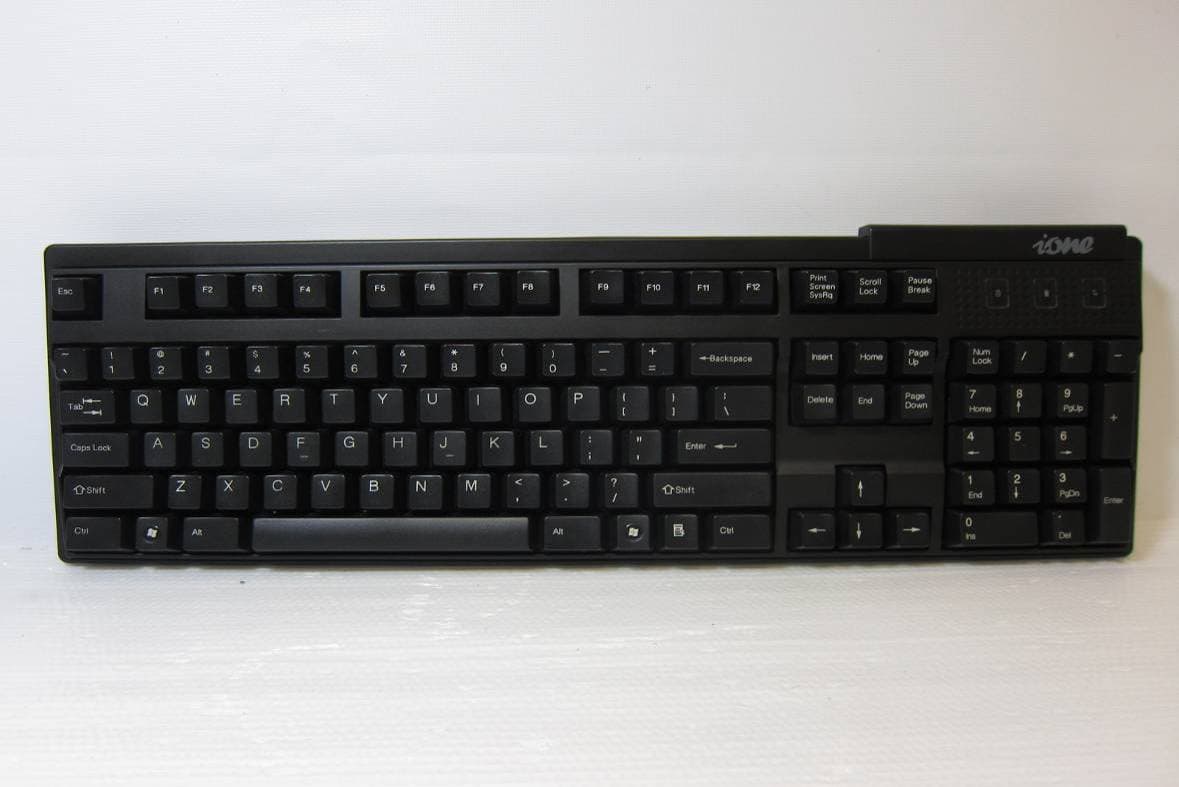
F2QSCORPIUSU9WL
May 02, 2011Wireless Keyboard
Equipment Class
DXX - Part 15 Low Power Communication Device Transmitter
F2QRFLIBRA-S10HU
Dec 09, 2010Wireless Presenter Mouse
Equipment Class
DXX - Part 15 Low Power Communication Device Transmitter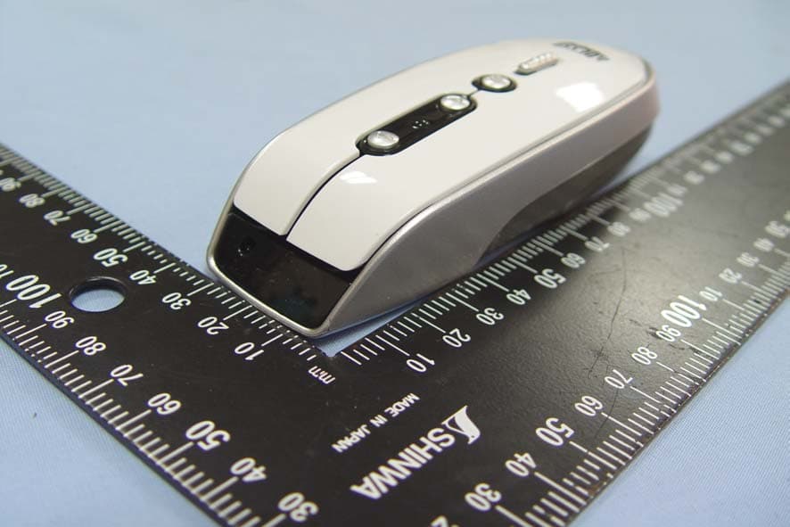
F2QRFLYNXP2
Sep 08, 2010Wireless mouse
Equipment Class
DXX - Part 15 Low Power Communication Device Transmitter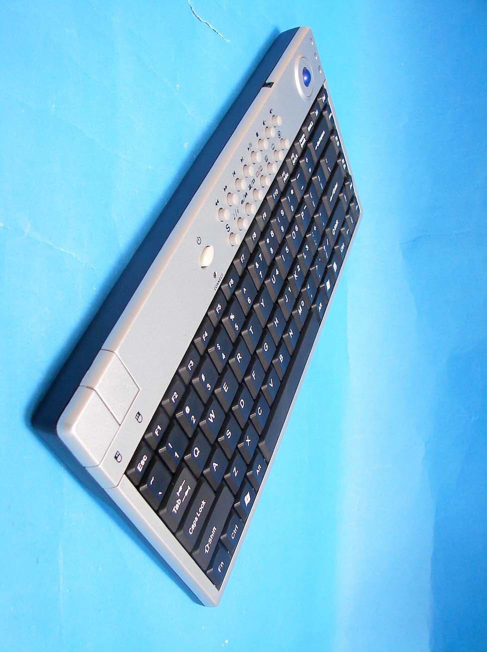
F2QSCORPIUSP20MTU
Jul 01, 20072.4 GHz MCE Keyboard with Optical Trackball
Equipment Class
DXX - Part 15 Low Power Communication Device Transmitter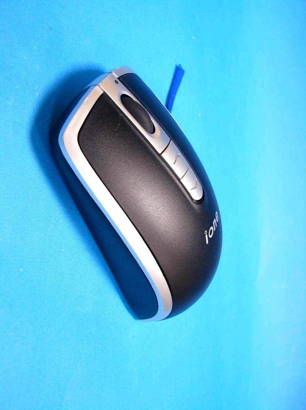
F2QLYNXR7AU
Apr 08, 200727MHz OPTICAL MOUSE
Equipment Class
DXX - Part 15 Low Power Communication Device Transmitter