F9C-CBAMMUtility Meter Transmitter
Schlumberger Sema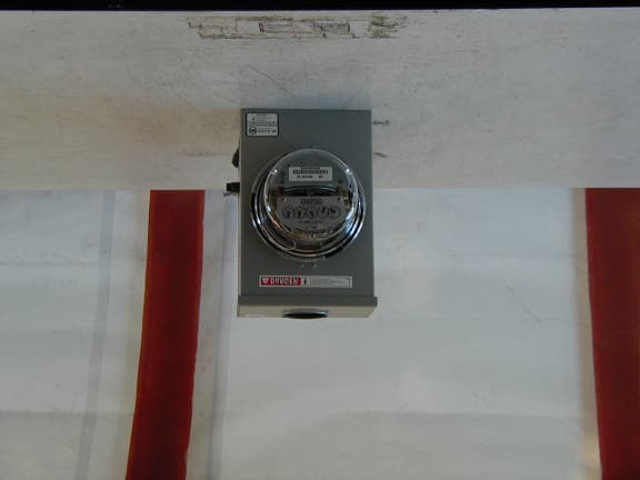
Click to zoom
Application Details
- Equipment Class
- DSS - Part 15 Spread Spectrum Transmitter
- Date of Grant
- May 03, 2002
- Application Purpose
- Original Equipment
- Date of Application
- May 03, 2002
- Equipment Note
- Utility Meter Transmitter
- Frequency Range
- 917.58000000 - 917.58000000
- Company
- Schlumberger Sema
- Country
- United States
Documents & Files
Document Text
Text extracted from the exhibit documents filed with the FCC. Open a document above to read the original.
Users Manual
MPI: GE, 240v, single phase, Meter Remanufacturing Process 97-xxxx, Rev :G Title: MPI: GE, 240V,Single Phase, Remanufacturing Instructions (for Third Party) Doc. Number: 97-xxxxRevision: A Page: 1 through 13 Process Owner: Process Development Engineering Revision History ECO/ECNRevDateAuthorPagesDescription of change A12/19/01M.Qua14Initial Release MPI: GE, 240v, Single Phase, Remanufacturing Process 97-xxxx, Rev:APage 2 of 13 Table of Contents: 1. Purpose 2. Required Tooling 3. Inspection 4. 240v Module Disassembly 5. 240v AC Cable Disconnection 6. Interrupter Disassembly 7. Power Cable Installation 8. Interrupter Instalation 9. BAMM Installation 10. 120v Additional Parts and Tooling Requirements 11. 120v Specific BAMM Installation 12. 120v Specific AC Cable Connection MPI: GE, 240v, Single Phase, Remanufacturing Process 97-xxxx, Rev:APage 3 of 13 1. Purpose This procedure details the disassembly of 240V modules and the retrofitting of the single phase, 240V BAMM(40-1716), 240 V BAMMCCSK (40-0318), and 120 VBAMM onto a GE I70- S meters. 2. Tools and Materials Required NOTE: A grounded wriststrap must be worn during assembly. The following tools and materials are required for meter retrofit: CellNet Part No.Description Used OnQuantity 40-1716GE 240V Single Phase BAMM240VBAMM1 40-1719 GE 120V Single phase BAMM 40-0318GE 240V Single Phase BAMMCCSKBAMMCCSK1 n/aGE I70 Meterall1 29-1126GE interrupter (labeled w/”G”)all1 17-1188GE interrupter installation tool (Spacer=0.225”,NEW) 240V BAMM/1 BAMMCCSK 19-0035240V BAMM AC cable( new spring clip)240VBAMM/2 BAMMCCSK 22-0557GE housing mounting screwsall2 n/aNeedlenose pliersall1 n/aPhillips #1 screwdriver (electric)all1 n/aPhillips #1 screwdriver (manual)all1 Other tools that may be required to remove the nameplate, depending on the age of the meter: - Phillips #2 screwdriver (manual)all1 - Chisel blade screwdriver, 1/4”all1 - Spintight 1/4” nutdriverall1 n/aOrange stick (or equivalent)all 1 n/a New AC wire installation tool (I70 S-I, I70 S-II) 240V BAMM/ 1 BAMMCCSK MPI: GE, 240v, Single Phase, Remanufacturing Process 97-xxxx, Rev:APage 4 of 13 DISASSEMBLY INSTRUCTIONS 3.Inspection (refer to 96-0072, Retrofit Meter Quality Acceptance Criteria) 3.1Inspect the meter and cover for the following: - Meter and cover cleanliness, and no moisture inside the meter base - Unacceptable base damage - Lightning arrestors are in place and undamaged - Filters are in place - Cover seal (gasket) is in place - Insure that the meter is not unidirectional -Verify that the hi-pot barrier is in position 3.2Verify that the AEP code on the label matches the meter type: 3.3 Module Inspection: Make sure the green PCB board is securely screwed into the BAMM/BAMMCCSK enclosure. There should be no visible gap between the top edge of the PCB and the top edge of the plastic enclosure. 4. Module Disassembly 4.1 Carefully remove glass cover from meter. 4.2 Remove screws from module using a Philips #2 Screwdriver. Always use a manual screwdriver when unscrewing the module from the meter in order to prevent debris from falling into the meter. 4.3 Carefully place module facedown on the ESD mat on the workbench after disassembly. Figure 1 BAMM Interrupter Note: Place ESD wrist-straps on prior to module disassembly procedure. MPI: GE, 240v, Single Phase, Remanufacturing Process 97-xxxx, Rev:APage 5 of 13 5 AC Cable Disconnection 5.1 Disconnect AC cable from the module. Use needle nose pliers to disconnect power leads from module. Gently grip on red AC cable tabs with needle nose pliers and disconnect the power leads. Pay close attention not to touch PCB with pliers and not to bend connection tabs on the board. Do not rotate tabs when disconnecting power leads. (Refer to Figure 2) 5.2 Disconnect AC cables from Current Coil. Use needlenose pliers to disconnect power leads from current coil. Grip on the edge of the superclip and gently remove clip from current coils. Remove any debris resulting from disassembly of the superclip from the copper coil. 5.3 Disregard and discard old cables. 5.4 All disassembled modules must be placed in ESD bags for storage. Note: Old modules (RTOMM) have a different set of cables from the new generation of modules (BAMM/BAMMCCSK). Both types of cables are NOT exchangeable. The RTOMM cables have different inline components on each of the two cables. One of two RTOMM cables has a fuse incorporated on the cable and the other cable has a resistor incorporated on it. The BAMM/BAMMCCSK have 2 identical cables WITHOUT in line components. RTOMM Component Side Resistor cable connector Fuse cable connector Figure 2: Power Cable Orientation MPI: GE, 240v, Single Phase, Remanufacturing Process 97-xxxx, Rev:APage 6 of 13 6. Interrupter Disassembly 6.1 Use needle nose pliers to remove interrupter from disk shaft. Gently pull the interrupter from the disk shaft with the needle nose pliers. Pay close attention when removing the interrupter and make sure that minimal force is exerted on the shaft. The shaft is extremely sensitive to force and can easily be bent when subjected to pressure 6.2 Disregard & discard old interrupters. MPI: GE, 240v, Single Phase, Remanufacturing Process 97-xxxx, Rev:APage 7 of 13 ASSEMBLY INSTRUCTIONS Important Regulatory Requirements/Statements This device complies with part 15 of the FCC rules. Operation is subject to the following two conditions: (1) This device may not cause harmful interference, and (2) this device must accept any interference received, including interference that may cause undesired operation. This device must accept any interference received, including interference that may cause undesired operation. The BAMMCCSK module is factory installed and is inaccessible to the user. The module must be sent back to the factory for any retrofit or maintenance required. The antenna used for this transmitter must be installed to provide a separation distance of at least 20cm from all persons and must not be co-located or operating in con…
Text truncated - open the document above for the full version.
Cover Letter(s)
Page 1 of 6 RE: SchlumbergerSema FCC ID: F9C-CBAMM 1) The address for SchlumbergerSema given on the 731 form does not match the FCC data base. The 731 lists Schlumberger Sema as the applicants name, yet the test report states Schlumberger- RMS. Please explain. Schlumberger-RMS is a division of SchlumbergerSema. This company has different divisions located in different states, each with a unique name to identify the type of product they design and make. All divisions pertaining to Schlumberger will used the assigned FCC grantee code for their product. 2) The Theory of Operations discusses this transmitter board being installed in the Landis & Gyr MS-II, MX, GE (excluding I70S) and ABB, yet only one meter is listed in the report. Please explain and provide detailed information as to what the differences in these meters? Thetransmittercanbeusedinvariousmeters. Wehavepreviouslysubmitteddatatothe FCC for the device tested in a single meter as being representative of all meters. The basic meters are very similar, with minor differences in the meter housings. The meters have a metal base and a plastic housing. The transmitter is optimized to radiate its maximum field strength when installed in the meter. If necessary, Schlumberger will apply for permissive changes to the device for different meter housings. 3) The submittal seems to support a modular approval but does not request this, provide the necessary information for modular approvals, nor was the sample tested in a stand alone configuration. The users manual also mentions retrofitting of the board. This also tends to suggest a modular approval. A limited modular approval (LMA) may be a suggestive course of action here. If tested in a stand-alone configuration (i.e. outside of a meter housing), the field strength is significantly reduced. The transmitter design is such that its output is optimized when it is installed into a meter. For this reason, Schlumberger have always tested similar devices installed in a meter. 4) From comparing the external photograph and the labeling information, it is not clear where the label is placed and if it is readable from the outside of the device. Please provide further information and/or photographs. A photograph of the location of the FCC ID label has been uploaded. Page 2 of 6 5) Please provide a photograph showing placement of the board inside the device. Additional Photos of the internal meter has been uploaded. Photos will show were and how the transmitter board is located on the meter. 6) Please confirm that the EUT only operates on a single channel (note-test report states middle channel on certain tables). The device does only transmit on a single channel in the center of the allocated band. 7) Please provide a better/higher resolution schematic (page 1 of 4). The copy provided is partially unreadable. We have re-scanned page 1 of the schematics. The complete schematics will be uploaded as a revised file. 8) The theory of operation discusses that the unit is designed for low duty cycle and continuous transmissions are not possible (the TX will shut down due to excessive current draw). Please explain how the transmitter was exercised during radiated testing, and any special test methods that had to be applied to ensure maximization of the test results. Were the procedures given in the theory of operation (page 16 of 16) applied? If so, was the EUT in continuous transmit or was there still a duty cycle associated with its output? The Transmitter was set to transmit every 1-second. For all the products, we have tested, we used the following spectrum settings: The span was set to 0 Hz to capture the emission in a simulated time-domain setting. The sweep time was set to 10 second to capture at least 10 spectral lines. This allows the continuous rotation of the turntable, without having to stop every 5 or 10 degrees increment. The display line function is manually changed as the spectral line amplitude changes. This will help determine the angle and height that yield the maximum level. We have had a lot of experience in testing this kind of device and so have developed test techniques to allow us to maximize the signals from the device. 9) Please explain how average measurements were made given the possible nature of low duty cycle. Please note that FCC guidance for average measurements expect the transmitter carrier to be in continuous transmit. Application of the RBW = 1 MHz and VBW = 10 Hz may be inappropriate depending on the answer for question 8). Theunitwastransmittingonceeverysecondduringtesting(asstatedinquestion#8). Average measurements were made using RBW=1MHz, VBW=10Hz. Although not continuously transmitting, FCC has been approach with this unique transmitter. Since the transmitter is being force to transmit every 1 second (out of its ordinary true transmit protocol) FCC has allowed us to apply an additional Duty Cycle to the Average measurement for these particular transmitters only. Page 3 of 6 10) Please explain derivation of duty cycle correction factor for average measurements. The duty cycle correction factor of 13.15dB is based on a maximum transmission length of 22 mS in any 100mS period. Plots of the Duty Cycle for both OOK and CCSK modulation has been uploaded. NOTE: The lowest duty cycle correction value was used or applied for both OOK and CCSK modulations, average measurements during the radiated scan, if needed. 11) Please provide information regarding any change of the fundamental output radiated signal with respect to a variation of input voltage from 85% to 115% as specified by 15.31(e). Pages 7 - 9 of the Theory of Operations detail the power supply circuitry. The device is designed to operate with no change in supply voltage to the rf circuits with input voltage fluctuations exceeding the +/- 15% of the nominal 240V AC. The actual operating voltage range is 192V – 288V (page 4 of the Theory of Operations). 12) Please provide information showing sample calculations of Out…
Text truncated - open the document above for the full version.
Cover Letter(s)
Page 1 of 4 RE: SchlumbergerSema FCC ID: F9C-CBAMM Original Question #2) 2) The Theory of Operations discusses this transmitter board being installed in the Landis & Gyr MS-II, MX, GE (excluding I70S) and ABB, yet only one meter is listed in the report. Please explain and provide detailed information as to what the differences in these meters? Original Answer: The transmitter can be used in various meters. We have previously submitted data to the FCC for the device tested in a single meter as being representative of all meters. The basic meters are very similar, with minor differences in the meter housings. The meters have a metal base and a plastic housing. The transmitter is optimized to radiate its maximum field strength when installed in the meter. If necessary, Schlumberger will apply for permissive changes to the device for different meter housings. New Question: If Schlumberger wishes this filing to be representative of multiple meters, then this fact should be clearly represented in the application and detailed information provided as to the construction variances between the meters (and justify why they do/do not affect EMI). Depending on the construction differences, test data may be required for each model, or at least to obtained in order to determine the worse case model. Without this information, the filing can only cover the product as tested. Construction difference between meter makes will likely require a permissive change (this is also a concern since the previous response also stated that the field strength is reduced increased when installed in the meter). However, please note that since the power measurements are performed radiated, if this significantly varies or increases within different meters, a new ID may be necessary. Please let me know how you wish to handle this issue. RESPONSE: Schlumberger-RMS is requesting approval for the Landis & Gyr model only. They will request permissive class II changes for the other models that were mention on the manual later in the future. Uploaded a letter stating the differences between the L & G model. Page 2 of 4 Original Question #9) Please explain how average measurements were made given the possible nature of low duty cycle. Please note that FCC guidance for average measurements expect the transmitter carrier to be in continuous transmit. Application of the RBW= 1 MHz and VBW = 10 Hz may be inappropriate depending on the answer for question . Original Answer: The unit was transmitting once every second during testing (as stated in question # 8). Average measurements were made using RBW=1MHz, VBW=10Hz. Although not continuously transmitting, FCC has been approach with this unique transmitter. Since the transmitter is being force to transmit every 1 second (out of its ordinary true transmit protocol) FCC has allowed us to apply an additional Duty Cycle to the Average measurement for these particular transmitters only. New comment: The FCC will allow you to apply both a duty cycle correction & Average Measurement to a pulsed or low duty cycle TX. However, the concern with this is that the Average Measurement is performed in an acceptable manner without the technique giving undue benefit due to the analyzers settings and the duty rate of the TX (usually, as the VBW of the spectrum analyzer is reduced, the sweep time of the analyzer increases and give an unintended benefit to the measurement). In these situations, the VBW should be increased to be sure the passband of the TX is still adequately captured during a single sweep (I have seen where VBW=1kHz work well in many cases). However, your previous response states that this transmitter has been discussed with the FCC. Please comment on this issue and/or provide plots comparing VBW's to ensure that the settings previously used did not provide an unintended benefit during the measurement. RESPONSE: Uploaded plots with comments. Label “Average and Power Measurements” Page 3 of 4 Original Question 12) 12) Please provide information showing sample calculations of Output Power (page 7 of 15 & 13 of 15). Were the units of the output power (dBm or mW)? Original Answer: The output power is calculated from the field strength using the formula: E = SQRT(30 P G) d where E = field strength (V/m), P = output power (Watts), G = antenna gain and d is the distance from the device under test (meters). From this equation: EIRP = PG = E 2 d 2 30 The output power stated in the report is the calculated effective isotropic radiated power expressed in dBm, based on the peak field strengths recorded. New Comment: The purpose of following the alternative test methodology (radiated measurement) is to obtain the calculated power into the antenna terminals, since limits to 15.247 are specified as conducted power. According to information in the filing (theory of operation, RF exposure info), the antenna gain is –5 dBi gain antenna. However for this calculation, an isotropic source was assumed. This calculation should use the claimed antenna factor in order to determine the expected conducted power. However, solving the above equation for a –5 dBi, the antenna conduced power equates to +28 dBm (634 mW). This creates the following concerns: a) the expected output power according to the theory of operation at the antenna port is +23 dBm which does not match the calculated value and b) at 634 mW, this device falls under excluded devices for TCB’s to approve and has to be submitted to the FCC. c) This affects the MPE calculation as well. Please explain. RESPONSE: Plots of the “Conducted” power output has been provided label “Average and Power Measurements”. +23 dBm was measured. The information for the antenna must not be correct since this will yield a 0 dBi antenna instead of the –5 dBi stated antenna gain. This was corrected in the user manual and MPE calculation was revised to reflect this. Page 4 of 4 Hopefully this answers all of your questions. Please contact me via [email protected] if you require …
Text truncated - open the document above for the full version.
Cover Letter(s)
Hi Tim, Bill Graff called me last week to talk about your concerns with the Schlumberger average readings we recorded during our testing. I understand your concerns with using a video average bandwidth of 10Hz to obtain the average value of a signal with a low duty cycle (although the FCC have accepted our data using this technique without question in the past). What I have done is to calculate, for the OOK modulation, two correction factors. The first converts the peak reading to an average reading based on the plots I submitted to you for OOK modulation (average bandwidth of 100Hz). The second is a duty cycle correction factor. These two factors have then be applied to the original peak readings to calculate the average reading. For the CCSK data, as I do not have a plot showing the peak to average correction factor, I have simply applied the duty cycle correction factor to the peak reading. In all cases the emissions are still below the average limit. Please advise if the data is acceptable. If so, we will upload a formal response to your concerns and hopefully put this application to rest. Regards Mark BAMM Test Data (modified).PDF Mark Briggs Director of Engineering Elliott Labs 684 W Maude Ave Sunnyvale, CA 94086 http//www.elliottlabs.com [email protected] Tel: 408 245 7800 Fax: 408 245 3499 Subject: Test Data for Schlumberger Cc: [email protected], David Bare <[email protected]>, [email protected] Page 1 of 1In 5/2/2002
External Photos
External Photo
ID Label/Location Info
FCC ID # FCC ID LOCATION
Internal Photos
Internal Photos Top w/ Cover On Top w/ Cover Off Internal Photos Bottom
Internal Photos
Location of transmitter board installed underneath the plastic enclosure FRONT SIDE OF METER (1 OF 2) Plastic enclosure with Transmitter board exposed FRONT SIDE OF METER (2 OF 3) Close-up of the transmitter board inside the plastic enclosure (3 of 3)
Internal Photos
Permanent antenna located on the back of the RF board section.
RF Exposure Info
CellNet Data Systems Confidential Last Saved: 05/10/99 5:55 PM Title: Evaluation of ER Exposure from CellNet Transmitters for General Population / Uncontrolled Exposure Methodology: Using Table 1 in Appendix A of FCC OET Bullentin 65 (Edition 01-01), the Maximum Permissible Exposure limit for general population / uncontrolled exposure is specific as a power density: MPE = ƒ / 1500 milliwatts per square centimeter, where ƒ is in MHz (between 300 to 1500 MHz) Averaged over 30 minutes. Based on spherical surface around the source, the minimum distance D can be computed as: D = SQRT ( EIRP / 4 ∏ * MPE) Average transmit power (dBm) Antenna gain (dBi) Duty cycle (average over 30 minutes) Avg EIRP (dBm) Avg EIRP (mW) Frequency (MHz) Max permitted power density Minimum distance (cm) Power Density at 20cm (mW/cm 2 ) 23 0 .01% -17 0.02 0.05 0.00 23 0 N/A 23 199.5 917.58 0.612 mW/cm 2 5.1 0.04 Note 1: The BAMM will be used with an integral Loop antenna with a 0 dBi gain (refer to Installation Guide, page 7 of 13). Note 2: The RF safety exposure statement is included in the Installation Guide on page 7 of 13. Note 3: The peak power density (i.e. non-time-averaged) at 20cm from the device is below the maximum permitted level of 0.612 mW/cm 2 . The time-averaged value is much lower. Reference: [1] FCC OET Bulletin 65 (01-01 Edition), “Evaluation Compliance with FCC Guidelines for Human Exposure to Radio Frequency Electromagnetic Fields”, June 2001.
Test Report
Average Measurements The following plots compare the fundamental signal level when using different video bandwidths and a fixed resolution bandwidth of 1MHz. The summary of the levels is shown in the table following the plots. Plots using VBW = 10Hz were made at different sweep times with no significant change in the level recorded. RBWVBWSignal Level 1 MHz1 MHz103.95 dBuV 1 MHz100 kHz103 dBuV 1 MHz10kHz99.88 dBuV 1 MHz1kHz98.73 dBuV 1 MHz100Hz98.17 dBuV 1 MHz10Hz57.96 dBuV Summary Table The sudden change in level between VBW = 100Hz and VBW = 10Hz is due to the pulsed nature of the signal. The pulse period is of the order of 20mS, so it has a bandwidth of about 50Hz. The VBW acts as a low-pass filter, so VBW = 100Hz would have little effect on the signal level but a VBW = 10Hz would have a significant effect. Further, changing the sweep time has little effect on the overall signal level Output Power Measurement Output power as measured directly from the device (conducted measurement) gave a reading of 23dBm. The plot below shows the parameter used and includes a reference level offset of 30dB to account for the external attenuator used.
Test Report
File: R44859 Page 1 of 13 Electromagnetic Emissions Test Report and Application for Grant of Equipment Authorization pursuant to FCC Part 15, Subpart C Specifications for an Intentional Radiator on the Schlumberger-RMS Div Model: BAMM-CCSK FCC ID: F9C-CBAMM GRANTEE: Schlumberger - RMS Div. 125 Shoreway Road San Carlos, CA 94070 TEST SITE: Elliott Laboratories, Inc. 684 W. Maude Avenue Sunnyvale, CA 94086 REPORT DATE: September 27, 2001 FINAL TEST DATE: September 21, 2001 AUTHORIZED SIGNATORY: ______________________________ Mark Briggs Director of Engineering This report shall not be reproduced, except in its entirety, without the written approval of Elliott Laboratories, Inc. Elliott Laboratories, Inc. -- EMC Department Test Report Report Date: September 27, 2001 File: R44859 Page 2 of 13 Pages TABLE OF CONTENTS COVER PAGE...................................................................................................................................................................................1 TABLE OF CONTENTS..............................................................................................................................................................2 SCOPE............................................................................................................................................................................................3 OBJECTIVE...................................................................................................................................................................................3 STATEMENT OF COMPLIANCE..............................................................................................................................................3 EMISSION TEST RESULTS.......................................................................................................................................................4 LIMITS OF CONDUCTED INTERFERENCE VOLTAGE.....................................................................................................4 LIMITS OF RADIATED INTERFERENCE FIELD STRENGTH...........................................................................................4 LIMITS OF POWER AND BANDWIDTH...............................................................................................................................5 MEASUREMENT UNCERTAINTIES......................................................................................................................................5 EQUIPMENT UNDER TEST (EUT) DETAILS..........................................................................................................................6 GENERAL...................................................................................................................................................................................6 ENCLOSURE...............................................................................................................................................................................6 SUPPORT EQUIPMENT...........................................................................................................................................................6 EXTERNAL I/O CABLING.......................................................................................................................................................6 TEST SOFTWARE......................................................................................................................................................................6 TEST SITE......................................................................................................................................................................................7 GENERAL INFORMATION.....................................................................................................................................................7 CONDUCTED EMISSIONS CONSIDERATIONS...................................................................................................................7 RADIATED EMISSIONS CONSIDERATIONS.......................................................................................................................7 MEASUREMENT INSTRUMENTATION..................................................................................................................................8 INSTRUMENT CONTROL COMPUTER...............................................................................................................................8 LINE IMPEDANCE STABILIZATION NETWORK (LISN)..................................................................................................8 POWER METER.........................................................................................................................................................................9 FILTERS/ATTENUATORS.......................................................................................................................................................9 ANTENNAS................................................................................................................................................................................9 ANTENNA MAST AND EQUIPMENT TURNTABLE.........................................................................................................9 INSTRUMENT CALIBRATION...............................................................................................................................................9 TEST PROCEDURES.................................................................................................................................................................10 EUT AND CABLE PLACEMENT..........................................................................................................................................10 CONDUCTED EMISSIONS...................................................................................…
Text truncated - open the document above for the full version.
Test Setup Photos
Radiated Measurements Below 1 GHz Radiated Measurements 1 GHz Conducted Emissions
Contact Information
Applicant
Lee Littlejohn(Compliance Engineer)
Technical Contact
Elliott Laboratories Inc.Juan Martinez
[email protected]408-245-7800
684 West Maude Avenue · Sunnyvale, California · United States
Non-Technical Contact
Elliott Laboratories Inc.Juan Martinez
[email protected]408-245-7800
Test Firm
Elliott Laboratories LLCDavid Bare
Technical Specifications
| # | Rule Parts | Frequency Range | Power Output |
|---|---|---|---|
| 1 | 15C | 917.58 MHz - 917.58 MHz | 200.00 mW |
Other Applications from Schlumberger Sema

F9CC1A-1
May 12, 2004ELECTRICITY METER WITH DUAL RF TRANSMITTERS
Equipment Class
DXX - Part 15 Low Power Communication Device Transmitter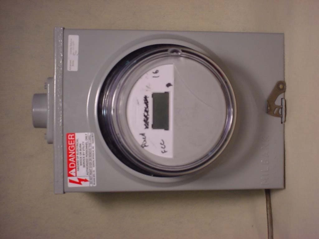
F9CC1SA
Apr 14, 2004Electricity Meter with Dual RF Transmitters
Equipment Class
DSS - Part 15 Spread Spectrum Transmitter
F9CSMFMM-1
Nov 14, 2002Wireless LAN Radio
Equipment Class
DSS - Part 15 Spread Spectrum Transmitter
F9C26-0288
Aug 27, 2002BLT 3 LAN Transceiver
Equipment Class
DSS - Part 15 Spread Spectrum Transmitter
F9CC1C-3
Apr 30, 2002Wireless Power Meter
Equipment Class
DSS - Part 15 Spread Spectrum Transmitter